
You are using an out of date browser. It may not display this or other websites correctly.
You should upgrade or use an alternative browser.
You should upgrade or use an alternative browser.
Steam engine for a sternwheeler
- Thread starter apointofview
- Start date


Help Support Home Model Engine Machinist Forum:
This site may earn a commission from merchant affiliate
links, including eBay, Amazon, and others.
- Joined
- Jun 28, 2011
- Messages
- 238
- Reaction score
- 480
Next up was the end covers one side just flat and the other needed a gland setup to seal the piston shaft. I dont have shots of cutting the brass down to size but you can see how it needed to be shaped. I wanted to fill the cavity that the end supports created I figure the less volume that has to be filled with steam the better. When installed the covers are just .050 from the piston at the end of the stroke. They also needed to be relieved where the steam ports are drilled. Hope that all makes sense; the pictures should add a thousand words or so.
I put the gland fitting in the cover and on the rotary table to remove the excess metal. Cutting that shape was harder than I expected. I drilled and tapped them and popped three holes to mount the assembly. I packed graphite tape from mcmaster carr around the shaft later tightened the cap screws just a little and it proved to be a good slick seal. An o-ring seals the cover for easy r/r.
I then took the end supports and drilled six holes, three counter bored to mount the support to the cylinder and three to mount the cover to the support all with 2-56 hardware.
Next came match drilling the ends to the cylinders. I used the alignment dowel I had made previously, hacked a groove in it to clear a drill bit and spent a long time getting the cylinder vertical!!
Sure enough I broke a 2-56 tap off flush in one of the cylinders!! I searched forever trying to find a way to get it out. I didnt have any more metal or the will power to make another one. I found the alum method of dissolving it out and it worked great! (Thats the pic of the cyl in the milky liquid)
You may notice i drilled the steam passages at some point but there arent any pics of that operation. The smaller holes are admission and the larger - exhaust.
Pete
- Joined
- Nov 14, 2009
- Messages
- 675
- Reaction score
- 104
Lovely work and nice to see the absence of computer aided machinery,sorry about that boys but it is my birthday and I have had a few ,and any way that is what I call model engineering.
Don
Don
- Joined
- Jun 4, 2008
- Messages
- 3,285
- Reaction score
- 630
Lovely work and nice to see the absence of computer aided machinery,sorry about that boys but it is my birthday and I have had a few ,and any way that is what I call model engineering.
Don
I was thinking how much easier I could make those parts on my CNC mill.

Getting the rotab setup for each arc cut needed real determination. Thm:
- Joined
- Jun 28, 2011
- Messages
- 238
- Reaction score
- 480
Thanks again for the complements ! That rotary table can mess with your mind !
The only reason I am doing this manually is I cant afford a CNC setup and I have no idea how to design something in a computer. Attaching pictures to these posts was hard enough to figure out. If I could use CNC I would !! A side note is that is seems CNC requires preplanning and that is something I dont seem to do much of. I usually get a general idea and then start cutting, so I design on the fly.
Next to muddle my way through was the valve block. Here is where slim to no plans and really no thinking beforehand comes up with such a strange looking design, but I have gotten used to how they look. I really cant explain most of the decisions, I just made up the final shape as I went. I knew I wanted orings on the steam and exhaust pipes so a recess was needed for those. I wanted to be able to bolt on the valve guides but I limited myself with all the metal I removed. Everything ended up fitting but drawing everything out sure would have helped. The bottoms of the holes where the valves seat were cut with an end mill to get them real flat after drilling. The hold down bolt pattern was just evenly spaced out but that just made everything else look un symmetrical. The placement of the bores for the valves was determined by lining them up with the holes in the cylinder supports, none of which are exactly the same. Once I made one I started the rest, another dumb idea, should have done the same operation to each one as I went.
All this was being done with only layout fluid and calipers so the parts from those days were very unique each time. I now have a poor mans DRO ( 3 grizzly remote digital scales ) and everything is much easier to do.
Happy Birthday Don !
Pete


The only reason I am doing this manually is I cant afford a CNC setup and I have no idea how to design something in a computer. Attaching pictures to these posts was hard enough to figure out.
If I could use CNC I would !! A side note is that is seems CNC requires preplanning and that is something I dont seem to do much of. I usually get a general idea and then start cutting, so I design on the fly. Next to muddle my way through was the valve block. Here is where slim to no plans and really no thinking beforehand comes up with such a strange looking design, but I have gotten used to how they look. I really cant explain most of the decisions, I just made up the final shape as I went. I knew I wanted orings on the steam and exhaust pipes so a recess was needed for those. I wanted to be able to bolt on the valve guides but I limited myself with all the metal I removed. Everything ended up fitting but drawing everything out sure would have helped. The bottoms of the holes where the valves seat were cut with an end mill to get them real flat after drilling. The hold down bolt pattern was just evenly spaced out but that just made everything else look un symmetrical. The placement of the bores for the valves was determined by lining them up with the holes in the cylinder supports, none of which are exactly the same. Once I made one I started the rest, another dumb idea, should have done the same operation to each one as I went.
All this was being done with only layout fluid and calipers so the parts from those days were very unique each time. I now have a poor mans DRO ( 3 grizzly remote digital scales ) and everything is much easier to do.
Happy Birthday Don !
Pete
- Joined
- Nov 14, 2009
- Messages
- 675
- Reaction score
- 104
I love this post,it shows real skill,and not just switching the machine on and watching it,I know it would be easier on Cnc but that is not always the aim.
Sorry if I'm ranting on but having been brought up old school I can't help myself
Don
Sorry if I'm ranting on but having been brought up old school I can't help myself
Don
- Joined
- Jun 28, 2011
- Messages
- 238
- Reaction score
- 480
Valves were next.
I used 416 stainless rod to make the valves and 360 brass for the guides and glands. Just basic turning for the valves. 2 sizes one for intake ( the smaller size ) and the larger for exhaust. Tried to get them as smooth as possible.
The guides were recessed to allow for the spring to be internal in the valve block. I have seen these type of engines have external springs also. I went with a heavier spring on the exhaust to keep it closed when the cylinder pressurized. The intake just needs a little since it has steam pressure trying to close it all the time. I used plain music wire for the springs for testing, but now its all stainless. I had to guess on what gague, coil spacing and overall size and adjust it later.
The image with the engine getting pumped up with air was to set the spring tension for holding pressure in the cylinder. I set it up for about 40psi, having no idea what it would take to run and just waited till it ran to adjust them. It looks crazy but the contraption was needed to plug all the openings.
I had to cut the springs way down because pressure to unseat 2 valves at a time per cam made for a lot of friction, which made the engine hard to turn over and very jerky. Right now it needs less than a pound of air to keep the paint can turning so a water load wont be that much more. The exhaust springs are down to around 20psi to crack them open.
Turning springs on my lathe was one of the easy things on this project, Just had to experiment with a few sizes of rod to get the right final diameter.
Only the steam valves have glands to limit leaking. I figured the exhaust has so little backpressure that it wont push much up the valve stem. I used the graphite tape as packing just like the piston rod gland. Very little compressed air leaks, time will tell how it works with hot steam.
This point in the project where mentally it became hard because I had to make 8 of everything and they had to be pretty dead on.
Next up the 2 cross heads and 8 lever supports,
Pete
- Joined
- Jun 28, 2011
- Messages
- 238
- Reaction score
- 480
Next I made the pistons out of brass and they were designed around a viton o-ring but that proved to be too much friction to let the engines run slow and steady. I am running graphite tape packed into the groove right now. Time will tell if it holds up to steam and high temperature.
The next images are forming of the supports that will hold the outboard pivot points for the levers. It took awhile to come up with a shape that would work, and they are all a little different to compensate for the valve block variations.
The last pics are the cross heads. I liked how these came out just winged the design using pictures in a book and the internet. I have a stainless pin for the pivot point held by a stainless 2-56 cap screw. I had to counter bore the crosshead later into the build where the nut sets, turns out that it was in the way of the connecting beam ( should have seen that coming ) . The pictures show the original config.
Pete
- Joined
- Jun 28, 2011
- Messages
- 238
- Reaction score
- 480
2 sets of 8 more identical parts Ugggg!
I needed to fabricate supports for the levers so I chose brass just for the looks and gave them a little bit of shape just to make them look better. Each one is drilled and tapped to secure it from underneath to the engine.
I had to make a couple of fixtures to allow me to clamp up the little towers in my vise in order to cut a slot for the levers.
I also made 8 little brass parts to attach the valve stems to the levers, but I guess I didnt take any pictures of making those. You can see them on the stems. They have cap screws in the pictures, but I ordered little 2-56 set screws to clean up the look. Those set screws use a seriously tiny allen wrench!!!!
The second to last shot is where I was figuring out where to cut the valve stems. ( they were left real long when they were made ) I also had to see how much room I had to build a support for all the wipers, rocker shaft and after rocker shaft.
I was going to mount the wiper block to the cylinder itself, but I got to thinking that that would be another heat sink that would make keeping the cylinder warm on steam that much harder. I went with cutting grooves in the block where the steam and exhaust pipes are which suspends everything over the cylinder and leaves room for insulation if I need it.
Whew thats enough typing for now !
Pete
kf2qd
Well-Known Member
- Joined
- Apr 1, 2008
- Messages
- 586
- Reaction score
- 76
The only sternwheeler I was ever on didn't really have an engine for propulsion. There were 2 double acting cylinders mounted on each side of the boat driving the wheel, and they had valving, but the "frame" was the entire boat. The only "engine" was an upright that ran a generator for lights and such.
- Joined
- Jul 16, 2007
- Messages
- 2,987
- Reaction score
- 1,055
Great work on your engine. I like you find it much easier to make some parts from a piece of round stock. That way you can cut most of the shapes before parting off. The only time I don't use this process is if I have to waste a lot of brass machining a part.
I have a great interest in paddlewheel riverboats and built one originally to be an RC model but when I got to the point of trying to make removable panels in the upper deck to get to the internals I opted to just make a scale static model.
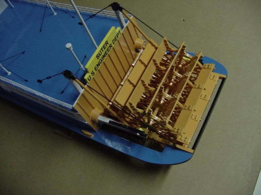
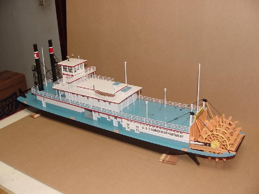
I have a great interest in paddlewheel riverboats and built one originally to be an RC model but when I got to the point of trying to make removable panels in the upper deck to get to the internals I opted to just make a scale static model.


- Joined
- Jun 28, 2011
- Messages
- 238
- Reaction score
- 480
Wow !! That is a great looking boat !!!!! The details are great especially in the paddle. Are those really u-bolts with little nuts holding all those paddles to the spokes on the wheel ? The railings are something else that is hard to imagine building....That is amazing. Is the paddle powered in any way for display ?
I havent really chosen a hull yet. I wasnt ever thinking 'scale'. My engine is the size it is because I wouldnt want to machine anything with smaller parts than this has at my skill level. So that being said a 1 gallon can size paddle makes for a BIG boat, so mine will be the monster truck style paddle boat with a large paddle relative to the hull. It has to fit into the mini van after all. I dont want to drag out the 1 ton dually to take a model boat to the pond !!
Pete
Dave Sohlstrom
Member
- Joined
- Oct 4, 2008
- Messages
- 195
- Reaction score
- 27
Here is an interesting history of River Engineers on the Middle Mississippi.
http://www.mvs.usace.army.mil/Portals/54/docs/history/River_Engineers_on_the_Middle_Mississippi.pdf
George
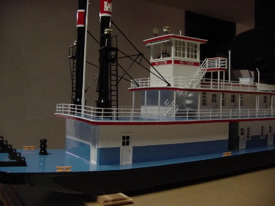
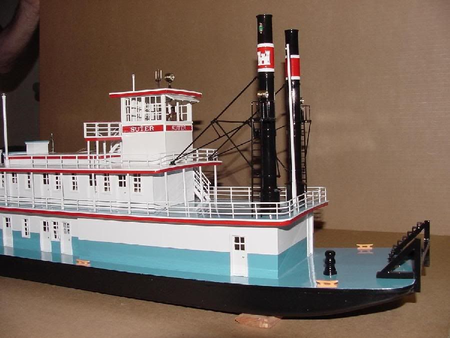
Beautiful model of the Suter.
Dave
http://www.mvs.usace.army.mil/Portals/54/docs/history/River_Engineers_on_the_Middle_Mississippi.pdf
George
Beautiful model of the Suter.
Dave
Last edited:
- Joined
- Jul 16, 2007
- Messages
- 2,987
- Reaction score
- 1,055
Hi Pete,
My boat is 38 inches long. It worked out to about 1/50th scale. The full sized boat was about 150 feet long. As I mentioned the intent was to make an RC boat but trying to put the curvature on the decks and add all the details made it just about impossible to make removable sections so it ended up as a 'scale model'. It was modeled after a real boat operated by the Army Corps of Engineers.
Yes the buckets (paddle blades) are bolted with U bolts and nuts. The pilot house is detailed with a table and chair, wheel and some fittings. The main hull and structure is made from Basswood. The paddlewheel and other wood bits are made from Maple. The fittings were all turned from brass and the smokestacks are plastic tubing. The railings were made from Basswood strips. I laid out the railings on a piece of paper, covered it with wax paper, pinned the main rails in place and then glued all the verticals in position.
Actually the blue in the pictures is quite a bit off from the model. The model is a medium/dark blue. This was the color of the original boat.
gbritnell
Last edited:
- Joined
- Jun 28, 2011
- Messages
- 238
- Reaction score
- 480
Gbritnell - That must have taken some serious time to build! What is the diameter of the paddle?
Dave – The link to history of River Engineers on the Middle Mississippi only sends me to my own thread, I would like to see what you intended to show me.
Now it was time to start working on the supports for the shafts that hold the valve rockers.
The little bearing blocks were milled from one hunk of metal. It took a little bit of fiddling with holding methods to get it on my rotary table. Once it was held I drilled the center hole and then cleaned up the block to the shape I wanted. I separated them and did a final facing to get them all the same thickness. I ended up changing the support block a lot because the rockers needed clearance below them to pivot and the bearing blocks held the shaft better if they were at the ends of the shafts rather than in the center. To change all that I cut down the support block and added a wider plate with 2 blocks on top of it to support the bearing blocks. I’m sure that wasn’t described well, but hopefully the pictures will show what I did. With all that in place I was able to locate where the bearings needed to be and secured them with more 2-56 cap screws.
The valve lever arms in these pictures were what I made first, but I didn’t like how they came out or how they looked so I remade them later, but these worked for now to locate everything. The rockers were made with just a simple jig in the vise to hold them in order to cut them all with the same angle. That angle was determined with pieces of cardstock cut to shape and pinned down at the various pivot points till I got the movement I needed.
There are not many pictures of the little parts that make up the two rocker shafts, I guess I was caught up trying to make it work. The shafts are stainless the arms are aluminum, the pins are brass rod, and the spacers to keep everything in place is brass tubing.
Here is a great web site that has nice drawings of the full scale engines these boats ran. I studied these drawings for a long time to understand what was going on. I didn’t add the complexity of a California cutoff, that would be a lot more work just to be more efficient.
http://www.alaska.net/~rmorris/steamboat1.htm
Pete
Dave Sohlstrom
Member
- Joined
- Oct 4, 2008
- Messages
- 195
- Reaction score
- 27
I corrected the link.
Dave
Dave
- Joined
- Jun 28, 2011
- Messages
- 238
- Reaction score
- 480
Thanks for the link update, which is a lot of neat information!
Next up was the beams to mount up everything. Here is where I wished I had bigger tools. The stock I had needed to be cut lengthwise in half. I dont have a band saw so cutting it with an endmill is my only choice. The problem I had was my table travel wasnt enough! I had to cut as much as I could with the mill and finish up with my sawzall with a metal cutting blade in it. It did the job but required several setups to make the parts look good their entire length. All that cranking to cut these bars wore me out, so I started another project to make a power feed for my mill. Necessity was the mother of invention once again. www.homemodelenginemachinist.com/f28/x2-mini-mill-power-feed-21466/
After that I set the cylinders up and drilled up the mounting points. I made the holes a little large to allow for tweaking the final positions to get smooth movement as the crosshead slides back and forth.
I made 4 guides for the crossheads next. I located them drilled up the mount points and then did a little extra cutting to dress them up. They came out just a touch low in their position relative to the crosshead, so a little shimming was required.
Pete
Similar threads
- Replies
- 152
- Views
- 10K
- Replies
- 413
- Views
- 39K