Steam Donkey

Home Model Engine Machinist Forum

Help Support Home Model Engine Machinist Forum:

This site may earn a commission from merchant affiliate links, including eBay, Amazon, and others.
Brian

That's the way I read it too. I would really appreciate seeing the rest of the drawings. Thanks for the offer. Can you email them? [email protected]

Jerry
 
Brian

Thanks for the e-mail. I really appreciate you efforts. The stuff is great. I went to the Cabin Creek site and found lot of great stuff. Thanks for pointing me there. I'll download from there.

Jerry
 
Your welcome :). I didnt relize how bir that CD was until I tried to print it. It is a total of 163 pages and 454 meg's of info. I could only print to PDF those 13 or so pages to get it below 10megs to send.
The rest of the cd is great, lots of drawings of how they used the Donkey engines etc...

View attachment AmericanHoist1.pdf
 
Fuel for the fire!

[ame]http://www.youtube.com/watch?v=TyEuTXPXOxU[/ame]
 
Captain Jerry said:
This is the big end of the con rod and is exactly the same as the cross head end. What do you call this type of connection?

bigendclamp.jpg

Jerry,
That is a strap bearing with a cottered joint. The flat taper pin or cotter in some designs was used to take up bearing wear. These were very common for all types of machinery in the days of steam for reciprocating or stationary joints.

Cheers Dan
 
That was a great video! A great engine!
I want to make one of those.
 
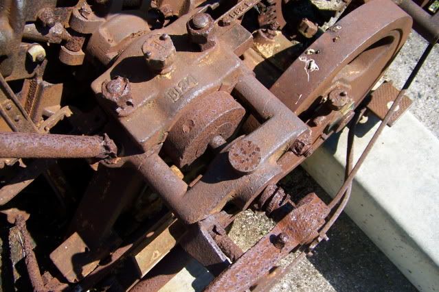
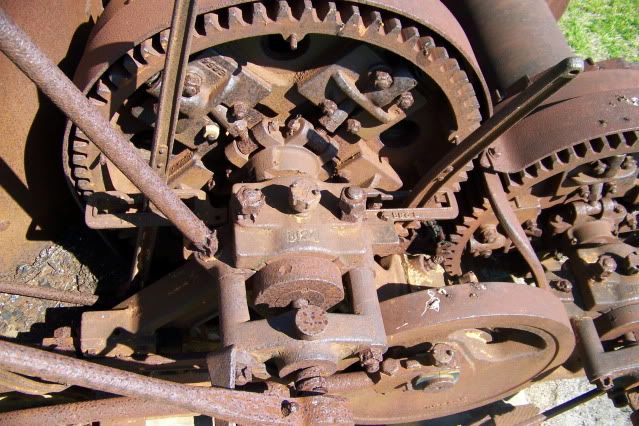
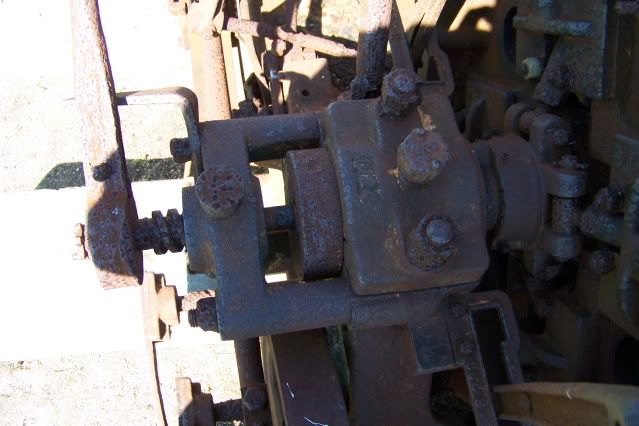
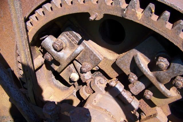
I have lots of pictures, lots of measurements, and lots of doubts. This is a very enticing project but I have not fully committed to it yet. Having the bones of this old engine so close at hand makes it all but impossible to ignore but the obstacles are many.

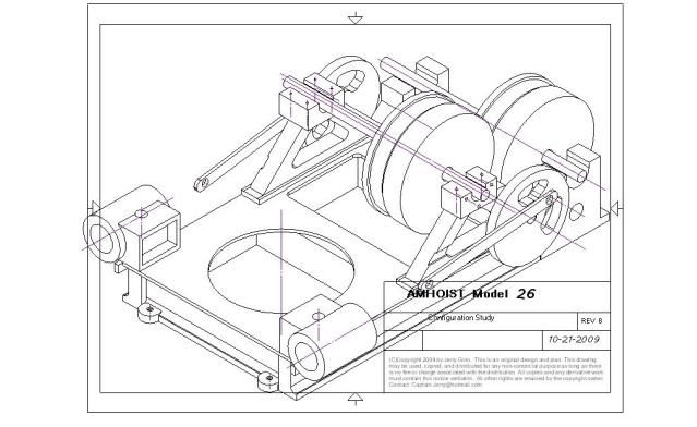
1. Plans. I would like to produce a model of THIS engine and while I have seen some plans offered, they are not this exact engine as far as I can tell. Close but not quite. This engine is one of the smaller models produced by American Hoist. Bore of 6.25", Stroke of 10" makes it a model 26 "EAGLE". There was a smaller one with 5.5" x 8" bore and stroke, the Model 24 "HABIT". These two models were unique in that the clutch and brake are on the same side of the drum. Larger models had the brakes on the opposite end of the drum for improved cooling. All plans and actual models of steam donkeys show the brakes and clutches separate.

2. Scale. If I make this model large enough to faithfully reproduce all detail would require a bigger shop and a bigger lathe. If I make it too small, some details will be compromised.

3. Complexity. I have never cut a gear. I have never cut a square thread. I have never cut a double start thread. Left hand double start square thread screw and nut, HA!

4. Live Steam. Maybe as a second phase.

configurationstudy.jpg

Frameassemblydetail.jpg


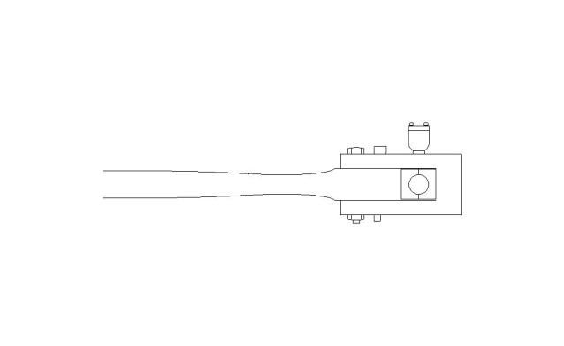
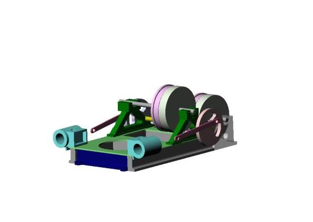
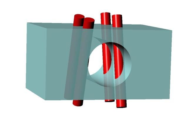
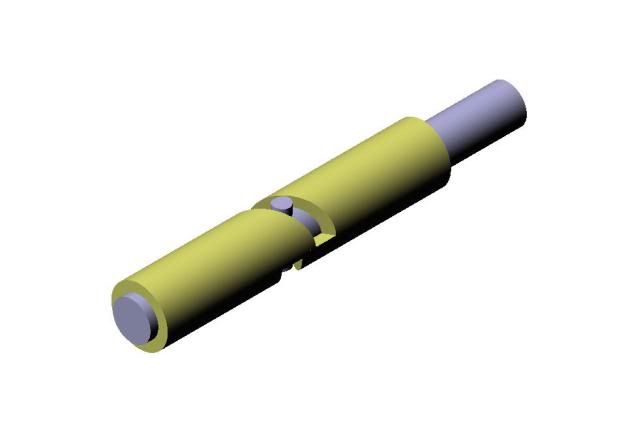
I think I'm beginning to get serious about this. Here is the results of some Alibre modeling I did last night. This is pretty accurate as to actual dimensions. I'm thinking of using a 1/10th scale. I haven't cut any metal yet, but I'm getting close. Suggestions are welcome

Jerry
 
Captain Jerry said:
Complexity. I have never cut a gear. I have never cut a square thread. I have never cut a double start thread. Left hand double start square thread screw and nut, HA!

I think I'm beginning to get serious about this. Suggestions are welcome

Jerry

CJ,

In some ways a left hand thread is easier than a right hand thread because you finish the cut in fresh air, (just watch for the tailstock centre).

The other thing to watch out for with a double start square thread is the helix angle. My way is to make a round toolbit holder and using a round piece of HSS grind the bit with 5 deg side clearance, then angle it in the holder to match the helix and grind the top parallel to the lathe bed and to the correct width. This keeps the strength in the bit.

To start use a parting tool and make a groove to depth and slightly wider than the thread, then cut the 1st start with the angled bit taking small cuts, (0.002-0.005) at the slowest speed and always engaging on the same number on the dial. My dial has six divisions so 1st start use 0, 2nd start use 3 as an example. The other way is to move the compound a distance equal to the pitch for the 2nd start in a two start thread remembering now to continue engaging with the # used for the 1st start. For my money, if you have a threading dial on the leadscrew that's the way to go, less chance of a boo boo. Also if your lathe has a high, (more than 60 rpm), minimum speed, I would turn the chuck by hand and isolate the power to the lathe.

Hope this helps and I hope you decide to pin the tail on this donkey.

Best Regards
Bob
 
Bob,

Thanks for the encouragement and the tips. Turning the chuck by hand makes it a lot less intimidating. I think I'll give it a try. I need both a RH and a LH screw. The LH presents more of a problem because my lead screw doesn't reverse. The are plans on the net for building a reverse mod but since I only need to do this once, I am thinking of two methods. I could either mount the tool upside down or mount the tool post on the back side of the work and then turn the spindle in reverse. What do you think?

The other problem is scale. What do you think is the smallest possible diameter? This will determine the overall scale of the model. This screw is used to engage the clutches. RH for the main hoist and LH for the front hoist.

Here is a pic.

Donkey005.jpg


Any thoughts on the nut?

Jerry
 
Captain Jerry said:
I need both a RH and a LH screw. The LH presents more of a problem because my lead screw doesn't reverse. The are plans on the net for building a reverse mod but since I only need to do this once, I am thinking of two methods. I could either mount the tool upside down or mount the tool post on the back side of the work and then turn the spindle in reverse. What do you think?

I think he easier way would be to mount the tool post on the back side of the work and then turn the spindle in reverse.

The other problem is scale. What do you think is the smallest possible diameter? This will determine the overall scale of the model. This screw is used to engage the clutches. RH for the main hoist and LH for the front hoist.

Looking at the photo the thread looks to be about 1” diameter so to have some meat left in the shaft I think the minimum shaft size is around 3/16” with a 1/64” square thread. Scale would then be 1: 5 or 1: 6

Any thoughts on the nut?

Yes and it’s the real challenge – 3/16” shaft = 5/32” bore so the absolute maximum shaft of the boring tool is 1/8”. All in all this starts to become impractical, so a work around is to make taps from silver steel, (drill rod) at the same time as the shafts are threaded. I would also compromise and make the threads single start.

Finally the ultimate compromise is to use standard V form threads.

Hope this helps

Best Regards
Bob
 
Bob,

Thanks for the input. The screw measures 1 1/4" and the lever that turns it makes an arc of not much more than 45 degrees so the thread pitch is very steep. The pitch looks like about 1 tpi. Single start thread probably not suitable. This particular part could be made as much as twice the overall scale of the model without affecting appearance. AT a scale 1:10 double for this part would be .25" 10 TPI double start. Possible? Acme thread form might be better.

Making taps? Now I am intimidated.

The length of the nut is fairly long, 2.5" actual or .25" at scale. This could be cheated to .3 without adverse appearance. I am thinking of making the nut a smooth bore to the OD of the thread form and then drilling holes that intersect the bore at the helix angle tangent to the thread root and inserting hardened pins. I think I could get four pins, two on each side of the bore. I would do a crap o cad here but I don't have the latest version. I'll try an Alibre model.

Jerry
 
CJ,

I took some measurements from the photo and with a SWAG for parallax I came up with this:

Thread OD 1.250”
Thread Pitch 0.500” = 2 tpi
Thread Lead, (2 start), 1.000” = 1 tpi
Thread 0.250” square thread.

Operating lever movement 45 deg

Therefore the distance of advance = 1 x (45/360) = 0.125” which does not seem sufficient if it is a dog clutch unless there is a further lever to multiply the travel to around 1”

Scale down 1:5

Thread OD 0.250”
Thread Pitch 0.100” = 10 tpi
Thread Lead, (2 start), 0.200” = 5 tpi.
Thread 0.050” square thread.
As there will be 60% core shaft thickness I think it should be OK but gut feel suggests it’s on the limit.

Operating lever movement 45 deg

Therefore the distance of advance = 0.200” x (45/360) = 0.025”

An acme thread form would be easier as you can allow a fiddle factor by reducing the size of the tool tip. However the pins you suggest would be a PITA with this thread form.

You are giving my grey cells pre-ignition I just hope I don't blow a clacker valve or head gasket. :big:

Best Regards
Bob
 
Bob

Easy on the clacker. Snuff out the cigarette, a big splash of Kentucky corn spirits in a cup of de-caf and put your feet up. That's my remedy.

Here is the nut with pins I described. The pins could be round or square section.

fabLHnut.jpg


This is not a dog clutch. When the lever turns, the screw advances and presses on the end of a pin fitted in a bore in the winch gear shaft which is turning with the drive pinion. This pin engages a spider that forces 4 friction blocks outward where they contact the clutch drum. The linkage actually reduces the travel of the motion but increases the force. The linkage does not knuckle over center. When the operator releases the lever, the springs visible in the pic force the friction blocks away from the clutch face. This is a really interesting mechanism and is probably what interests me most.

Here are a couple of pics of the motion. I'm working on modeling it now.

D346.jpg

Donkey004.jpg

Donkey006.jpg


Thanks for your thoughts and efforts. I am in way over my head here.

Jerry

 
OK. I don't think I can do it that way. The LH square thread rod and nut are too much at 1:10 scale. What I need is a way to move the rod axially a distance of about .010 when the rod is rotated 45 degrees.

I think I can do it this way:

clutchthrustassembly.jpg


I know, the above is a RH thread but doing it this way, the LH version is just as easy.

It should be fairly easy to build and although it probably wouldn't meet industrial standards it ought to do for modeling. The tube will probably be bronze, 3/16" OD, 1/8" ID. The rod will be 1/8" drill rod and the pin will be 1/16" drill rod.

I'm getting closer to a decision. When I get a little shop time this week I'll give it a try.

Jerry
 
Captain Jerry said:
Bob
Easy on the clacker. Snuff out the cigarette, a big splash of Kentucky corn spirits in a cup of de-caf and put your feet up. That's my remedy.

I really like the Kentucky and feet up but no fags and decaf :eek: :eek: :eek: that's more than I bargained for.

For someone way in over their head that sir is one very elegant solution. :bow: :bow: :bow:

Best Regards
Bob
 
I gave up nicotine when I was 40. I gave up caffine after breakfast when I was 60. I'll give up spirits when I give up the ghost... or maybe a few years after, just to be safe.

Jerry
 
Captain Jerry said:
I gave up nicotine when I was 40. I gave up caffine after breakfast when I was 60. I'll give up spirits when I give up the ghost... or maybe a few years after, just to be safe.

Safety first. And no one on this forum will argue with that. ;D
 
Jasonb said:
I still think it would be easy enough to cut a double start 1/4" square thread. I've done single start without any problems, did the nut as best I could with a lateh tool then chassed it with a home made tap.

Jason

Easy for some but too much for me at this point, but thanks for the encouragement. I may try it just for laughs.

Jerry
 
Back
Top