Rockerblock I.C.--Something a little different-

Home Model Engine Machinist Forum

Help Support Home Model Engine Machinist Forum:

This site may earn a commission from merchant affiliate links, including eBay, Amazon, and others.
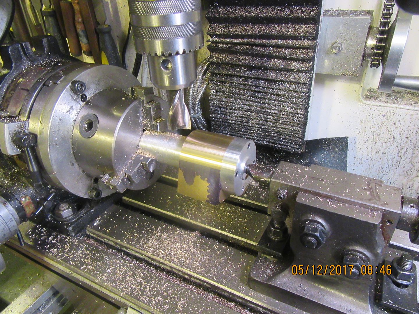
Yesterday evening I posted that I had one more fixture to build yet. This shows the simple fixture that I had to make, a piece of 1 1/4" shaft to fit thru the water-jacket, with a flange on one end to allow the four bolts to go thru the flange into the tapped holes in the end of the waterjacket. This let me set it up in my rotary table with chuck attached, and every 2 degrees of rotation I moved the mill table to pass the area I wanted to be rounded under the milling cutter. This of course was a lot of "back and forth", so I set the table stops on the front of the mill table to confine movement to the area I wanted milled.
 
So---we have a waterjacket. All the holes and clearances went in without breaking thru into the water compartment. I still have some fitting/polishing to complete, but all the heavy lifting is done. The big end of the con-rod squeaks by without touching. I'm happy with the results and I really do like the contrast provided by the brass.----Brian

 
Brian,

Congratulations on getting the water jacket done without breaking through to the other features: The shop gnomes, elves, and pixies must be with you and you must be holding your mouth right on this one.

I've been following along and I find this design pleasing. For some reason I like it more than the dual opposed engine you buillt earlier. Best wishes for the rest of the build.

Thanks for posting

--ShopShoe
 
Thank you Shopshoe. It is always nice when people stop by for a look and leave a comment. I like this engine too, just because it is so unconventional.---Brian
 
This mornings labours were limited to "Things I can make in the 3 jaw chuck." I wanted to make the muffler from brass, but decided to make it from aluminum, because of the weight savings. The weight wouldn't matter if it screwed straight into the cylinder head, but it doesn't. It screws into a 90 degree elbow which is screwed into the cylinder head, and I am afraid that the weight of a brass muffler would make the 90 degree elbow turn and hang down at some lop-sided angle. I chased down a very short stub of 660 bronze which was left over from something and made the top rocker pin and retainer, as well as the bottom rocker pin from the bronze. I am running out of things to build that will keep me away from the valve train. The ignition cam is made and installed, so all I have really left to do is make up the two 90 degree brass elbows and the oil cup.
 
As often happens, when I first design something from scratch, if I don't have a clear vision of what is involved in making a part, my imagination runs a bit wild. Then as I work my way thru the build, reality sets in. Such is the case with the cylinder oiler. It started life as a somewhat fanciful "add-on" oil reservoir. Although I could actually build it as "first designed", there is really no provision for keeping it in place on the cylinder. if I used any kind of Loctite to "glue" it in place, then I would never be able to remove the waterjacket if I had to, because of the small tube at the bottom of the oiler that fits into a hole on the top of the cylinder. So--Today I redesigned it as a "bolt on" It can be attached to the front of the waterjacket with two #4 s.s. bolts. I have a length of 1/16" o.d. x 1/32" i.d brass tubing that I bought a few years ago for a carburetor experiment. I will Loctite this tube into a hole in the redesigned oil cup. With this change, it both simplifies the machining of the oil cup, and it is also removeable by removing the two #4 bolts and lifting it straight up away from the cylinder.

 
So---I've got a running start on the two 90 degree elbows for the exhaust/induction. These elbows will be made up from two pieces silver soldered together. That's not a lot of machining, but its all I'm good for today.
 
Tonight we have an oil cup. Granted, it won't hold much more than a teaspoon full of oil, but I don't plan on doing any long haul trucking with this engine. The only reason I'm putting an oil cup on at all is that I hope to power this engine with propane. If I used my normal gas/oil mix, it wouldn't even need an oil cup. The oil-cup is just setting in place right now, without the 1/16" o.d. x 1/32" i.d. tube Loctited into it. I will wait until I have tapped the waterjacket and bolted it into place before I drill the oil hole in the top of the cylinder and Loctite the tube into the oil cup.
 
This next part is going to be--Ahhh--interesting. It is one of those multi purpose items that does 2 or 3 jobs. First and foremost, it provides a set of guides for the lifters to ride in. It also provides a place for the rocker arms to pivot. It acts as a "bolster" to lend some strength to the cylinder head plate which has a large "window" carved into it to access the cams which operate the valves. It could have been built from aluminum with bronze lifter guides pressed into place, but I opted for bronze because it adds some contrast to the mostly aluminum engine, and doesn't need any inserts in it for lifter guides.
 
I am constantly amazed by the amount of time required to make some of this stuff. I'm not slow at machining. Its just that there are so many steps and set-ups to make a simple part like this. I've just put in a complete 8 hour day making this lifter guide/bolster. It has turned out fine. I decided to make the rocker arm tower out of a separate piece, which will be bolted on. I will make it tomorrow.---Brian
 
Brian, I know what you mean, 75% of the time is used when setting up or changing tooling
Keep up the great work.

Cheers
Andrew
 
Looking great Brian. This is the first thread I've read since spending a week in hospital and the progress you've made is astounding. I think I might have to buy a copy of these plans off you when they're done.
 
This picture shows the finished bolster/lifter guide/rocker arm pivot finished and in place on the engine. The two open holes directly below the rocker pivot tower are where the valve lifters set. The camshaft and (as yet unfinished) cams set directly behind those two holes. (See picture without bolster in place.) The open slots on both sides allow me to get a hex wrench in there to lock the cams to the camshaft in the correct rotational aspect. The two open holes in the "cylinder head" are where the valves will be.

 
This has been a somewhat hither-thither morning. I made and installed two brass valve cages, dealt with a roofing contractor, and helped good wife sort out a ton of stuff in my garage as she prepares for a Parkinsons Charity yard-sale. The diameter of the valve cages are such that they can't be pressed into place with fingers alone, but slide in very smoothly when coated with #638 Loctite and pressed in with my 1 ton arbor press. I have sorted thru my box of springs and found the spring that will keep my valves in the closed position. The slight recess in the top of the valve cages contains the bottom 0.050" of spring so that it can't slide over and rub on the valves when they are installed. The picture showing the inside of the cylinder head shows up a lot of dirt that I didn't even know was there. The Macro setting on my camera sometimes does that. If I'm not interrupted in the next couple of hours, I may even have some valves made today.

 
Back
Top