Powered head adjustment-Chinese Mill

Home Model Engine Machinist Forum

Help Support Home Model Engine Machinist Forum:

This site may earn a commission from merchant affiliate links, including eBay, Amazon, and others.

Brian Rupnow

Design Engineer
Project of the Month Winner
Joined
May 23, 2008
Messages
14,991
Reaction score
8,285
Location
Barrie, Ontario, Canada
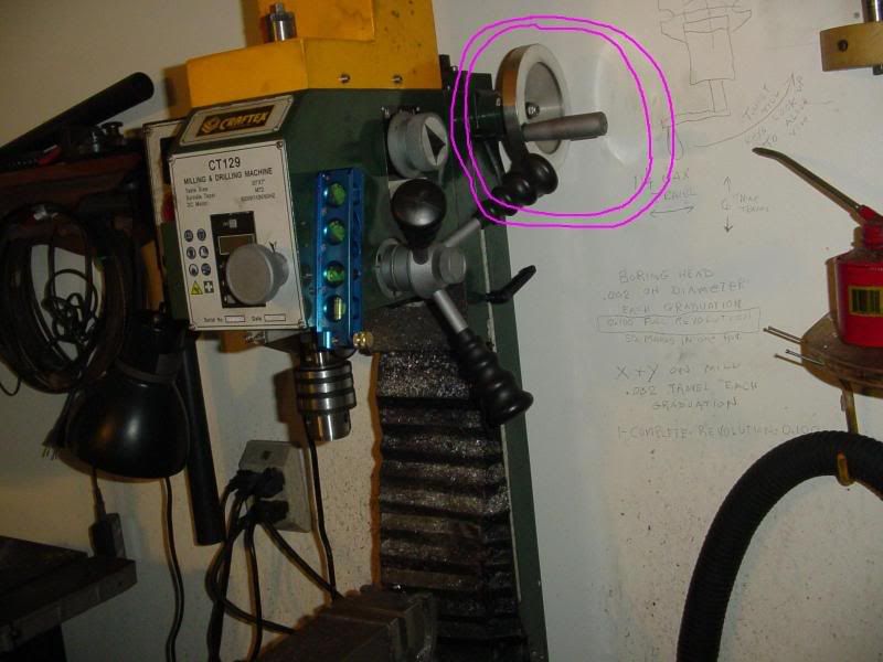
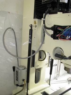
I have a CT129 Craftex mill from Busy Bee and the handwheel that I have to turn (in pink circle) to adjust the height of the head is high up at the rear of the mill. This happens to be right in the quadrant of movement that really bothers an old tendon injury in my right shoulder. Last night I was thinking of adding a power adjustment to the head. What immediately came to mind is the motor and gearset off an old barbeque rotisserie.---Trouble with that is that I doubt the motor is reverseable. Has anybody made a modification like that to their mill?----Brian
mill-tophandwheel001.jpg
 
brian, i wonder if you could use a windshield wiper motor or a power window motor?
i think they have lots of power and they will revers very easily, only drawback is you would have to have a d.c. power supply to run it.

chuck
 
Aermotor--I actually did think of that as well.--Hmmm---Could use the 12volt Bass boat battery and my 12V charger---It wouldn't be used all that frequently---
 
Not a power actuator but I have seen a version of my mill with two stainless cables running from the head over two pulleys down to two large tension springs (sort of like a roller door has), this takes all the 'load' off the handle when its unlocked. Ive been thinking about it for mine for ages..... trouble is I dont 'need' to do it (yet)....

Cheers Rob
 
Something like this--Remove top handwheel, put sprocket in its place, mount smaller sprocket on output shaft of some kind of gearmotor--connect with roller chain. My model shows gearmotor mounted on wall behind mill---in actuality I would probably build up support brackets off mill column.
MILLWITHMOTORIZEDHEAD.jpg
 
The more I think about it, the more logistics are involved.---Would either need limit switches as both "extremes" of travel, or a friction "slip clutch" in one of the sprockets.---or---a motor you could temporarily "stall" without danger of burning it out.
 
Brian
Automotive power window motors are electrically protected so when you stall them they temporarily open. They are reversable as well.
 
Thanks for your input guys. I am now researching a more manual approach using a set of bicycle sprockets and chain and a right angle drill adapter to move the handwheel into an easier to reach position. The tendon injury in my right shoulder only bothers me when my arm is at full extension and angled up at about 45 degrees.
 
I would think a potential problem would be driving the spindle assembly downward and the possibility of tooling and materials coming in contact long before you got to the lower limit of travel.

The early C4 generation (84-96) Corvettes headlights used a set of switches internal to the motor. They used a worm gear with springs on both ends. If the torque was too high caused by a stall or jam the worm gear would push against the switch and shut down the motor.

They moved to a solid state circuit by about 1988 (not sure) that sensed a current spike caused by a stall and shut down the motor. I converted my 85 over to the newer headlights and control system. The Trans-AM used the same control module for its headlights. I paid $5 for a used module at a junk yard.
 
So---This morning I went scrounging!!! First, down to the bicycle repair shop, where I scrounged a pair of small sprockets and a length of chain. (I actually paid for a new master link.) Then over to one of my fabricators where I begged 3 pieces of mild steel round bar to make hubs, out of there shorts rack. (Had to promise they will get to quote on the next job I design (IF I EVER GET ANYMORE FRICKIN WORK!!!) Then up to BusyBee Tools, where I actually had to PAY $25 for a right angle gear box. (actually its a 90 degree drive adapter for a 3/8" electric drill.)
SCROUNGING001.jpg
 
Well, this gets the handwheel for adjusting head height down to a much more comfortable position for me to reach. Two small bike sprockets and a peice of bike chain. ---And I don't have to worry about limit switches or power supplies.
MILLTABLEWITHBIKESPROCKETS.jpg
 
Looks like a good idea so far Brian, but where, in the great scheme of things, does the right angle drive come in?
 
Tel--I had so many tentative plans in my head this morning when I got up, and the right angle drive was one of the potential scenarios, powered with a dedicated 3/8" reverseable drill. The fabricator I went to beg the steel from has his shop utterly and completely on the far side of town from where I live---In fact he couldn't be any farther away and still be in the same city. And it just so happens that Busybee Tools is almost beside that shop. I figured that sooner or later, I was going to need that right angle gear set-up (for something) and as it was on sale for less than $20 I thought "Better buy it anyways and save a trip." The plan I'm working on mightt still morph into a powered set-up---to do that I would drop the lower sprocket even farther, hook the right angle drive onto it, and bring a shaft out below the table to a dedicated 3/8" drill.
 
Brian, thanks for starting this thread because it pointed me towards a problem that I had in past identified, but never put any real thought into. I had seen the above mentioned cable and spring design but at the time, thought it 'looked' messy. Probably worked ok but I didnt like the business of the result.

Your problem is much different to mine. Physically Im ok its just that my mill is large and lifting the head up takes a bit of effort.... not too much but enough for me to think bugger that would be nice.. etc etc..

Enter the 'solution'...... I have several of these laying around 'new' from a previous life so... a no cost 'fix' at least for me.... these things arent necessarily cheap and junkyard units are normally just that ... junked.....

Head is in the 70kg range and these will support 30kg (approx ea) so 2 required.

Cheers Rob (not 'my' idea... I 'sourced' it from another site ;D

gasassist1.jpg
 
Yesterday afternoon I made the hubs for the two sprockets. Nothing spectacular here, just simple turning. I will weld the sprockets to the hubs with my mig. Today I actually got a new engineering contract HOORAY!!! ------- so didn't do any work in my toy shop.
HUBSANDSPROCKETS002.jpg


Congrats on the contract Brian. Eating is more important than playing. Darn it anyway. :big: :big:


Ron
 
Fellows, its been a long, hungry year!!! Going through my invoice book last week, I see that I have worked 3 months out of the last 10 1/2. I have been through these recession/depression cycles about 4 times since I started working in 1965, but I was always working for big companies at the time, and as big companies don't like to lose their engineering staff, I was always protected. This is the first one I've rode out since I registered my own company 10 years ago, and all I can say is that I'm damn glad my kids are grown, my house is paid for, and my wife still works.
 
Brian, you must not watch much television, they say things are going to be great, jobs created and on and on it goes, course that is not going on where I live, I work in the oil field and its real bad and not hope in sight, we have worked all our lives what else shall we do, hope it gets better soon for you, Lathe Nut
 

Latest posts

Back
Top