PM research red wing air cooled drawings

Home Model Engine Machinist Forum

Help Support Home Model Engine Machinist Forum:

This site may earn a commission from merchant affiliate links, including eBay, Amazon, and others.

dkwflight

Well-Known Member
Joined
Sep 4, 2015
Messages
113
Reaction score
24
Hi
I am interested in the 1/3 scale air cooled engine dimensions.
I need to acess if I can do the kit on my 9 x 20 lathe and little else machinery.
Dennis
 
THe kit is sold by PM Reasearch. THe Red Wing air cooled engine
Dennis
 
I've just had a look at the PM Research site and the Red Wing engine.
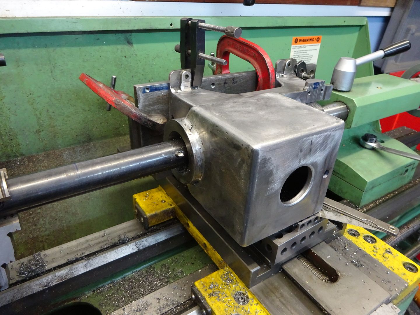
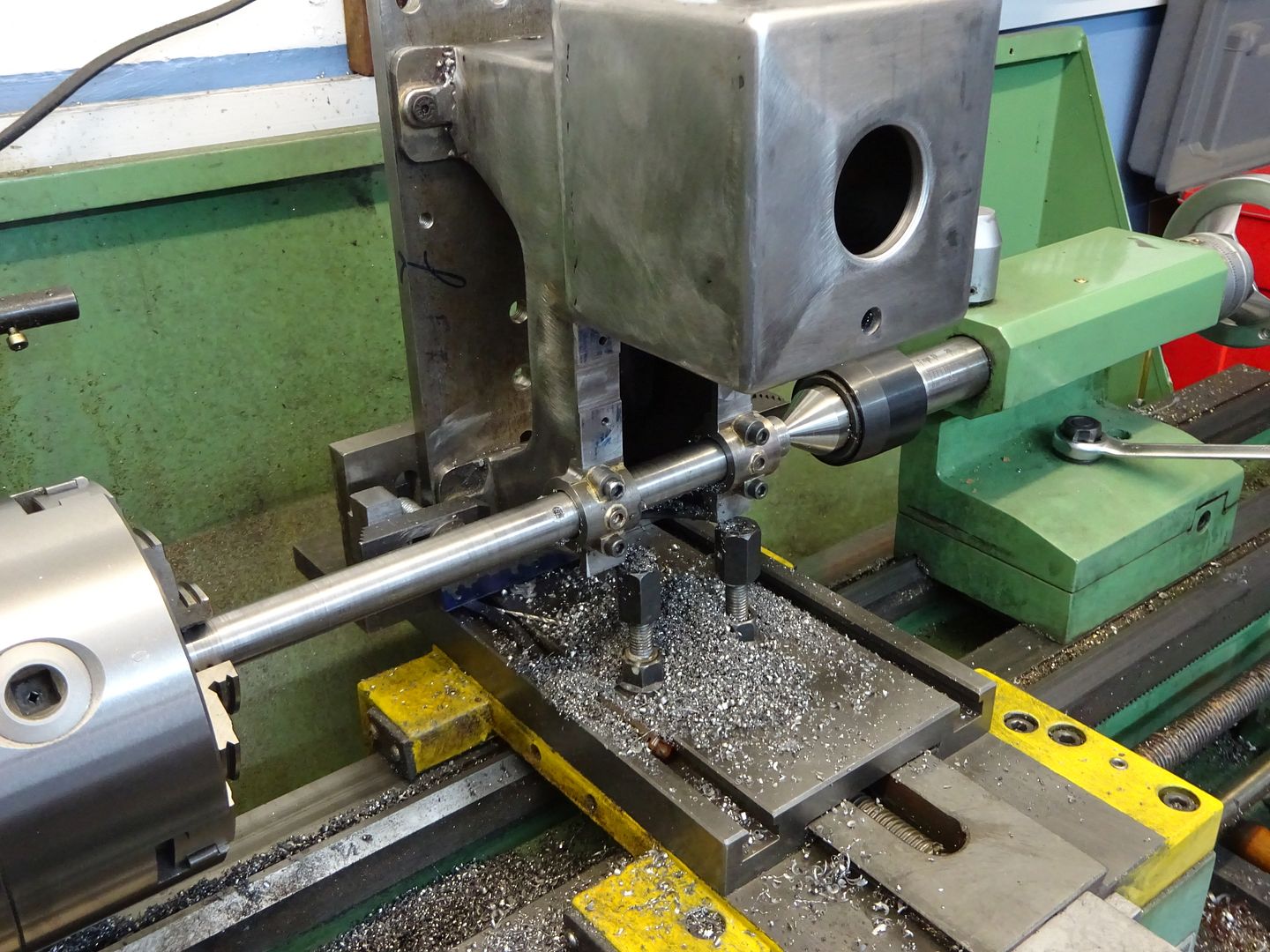
Normally, the flywheel diameter is the limiting factor for lathe work. Other bulky bits would be machined on the mill. However, without the use of a milling machine, you would need to hold the crankcase on the cross slide. Do you have sufficient cross slide travel to clean up the bottom? Will you have sufficient centre height to machine the crankshaft bearing housings with the base at the correct angle?
You do have Tee slots on your cross slide?!
Maybe possible, but you would need a lot of 'out of the box' thinking.
Just my opinion, others much more clever than I could offer solutions.

Dave
The Emerald Isle
 
Last edited:
Hi
I have been thinking about how to do the air cooled Red Wing engine on my 9 x 20 lathe.
I was thinking about doing the bore as a line bore operation, moving the cylinder mounted on the carriage.

So I am looking for a set of print / instructions. I would buy a used set of prints from someones kit.
 
SAM_1225.JPG
 
Being a 9 in lathe there is only about 2.4" to spindle center above the T slots
Dennis
 
centre line of the engine is 2.580" above the bottom but should not be a problem if you use an angle plate to mount the casting to so the casting is on it's side to do the cylinder bore and stood on end to do the crank bearings, something like this

DSC01524.JPG


DSC01534.JPG


As for teh bottom a bit of work with a file and then rubbing over a sheet of emery on a flat surface should suffice,
 
the water cooled(I'm assuming is pretty similar) is calling for a 2.625 from the bottom. it looks like 3.342 wide with the main bearing bosses sticking out the most. and an 8 in flywheel. maybe some fairly careful disc sanding on the bottom then on to emery on the bottom. if you were to stick a rod thru the rough cylinder bore and also thru the rough main bearing holes you could measure down to a flat surface to determine where on the bottom to grind off to get it parallel and square to the rough bores so you don't run out of material in the finish bore the print asks for parallelism of .002 " between the center lines of the bores. I can't see height being that critical , but 90 deg. squareness of the crank bearings to the cyl. bore is.
 
I built my water cooled on my South Bend 9. I did not have a milling machine. A friend of mine whose dad was a machinist in the 40's thru 60's had acquired many files from his fathers estate. Ford motor co supplied these. (Fell in his lunch box?) He gave most to me so I did have a supply of good files. It took a lot of elbow grease and sweat and thinking outside the box, but it did work. I did finish the project and the engine runs well. Check Red Wing Engine web sites. I found a lot of different ways of doing this without a mill. The best part is that it MOTIVATE me to find a mill.
 

Latest posts

Back
Top