- Joined
- Mar 13, 2012
- Messages
- 583
- Reaction score
- 62
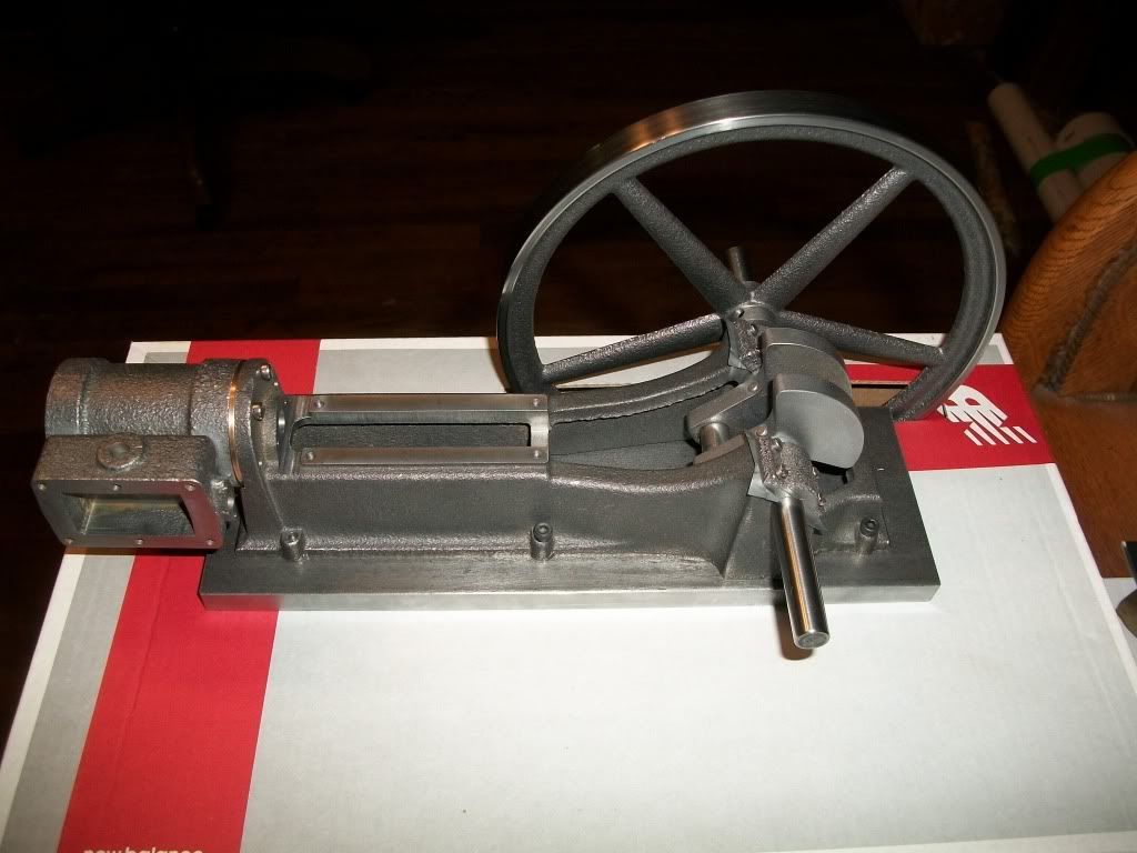
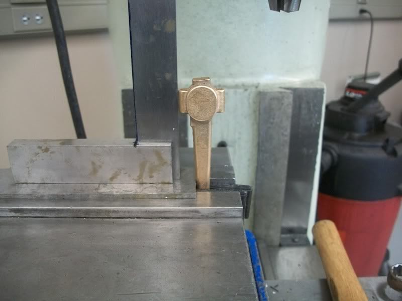
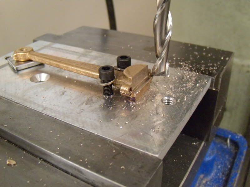
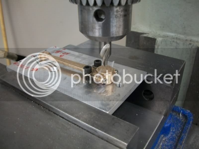
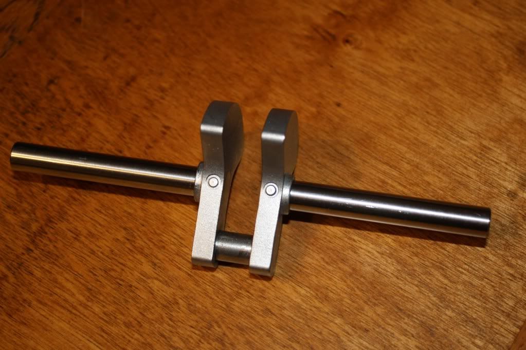
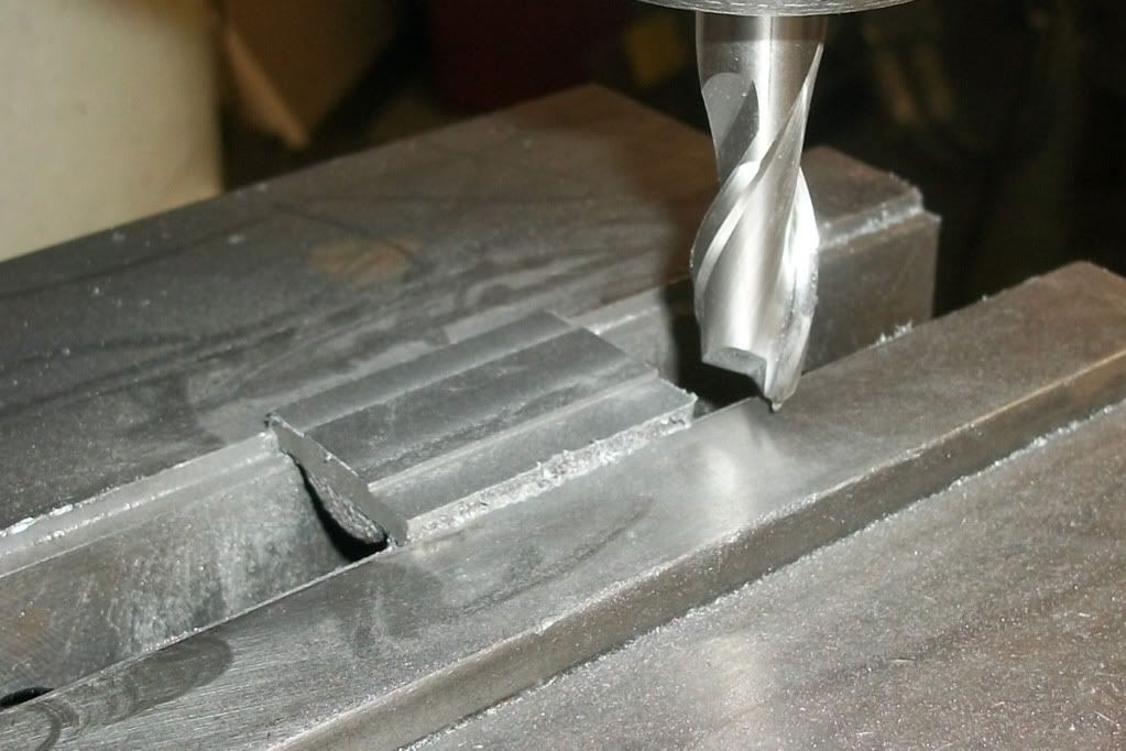
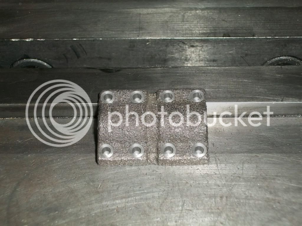
OK, I am deviating from the plans again. I decided that I would be happier if I built up a crank rather than use the cast one from the kit. I got wrapped up in the work tonight, and forgot to take pics, but here is the connecting rod journal attached to the side plates. (I don't know what the correct name for the parts are ??? )
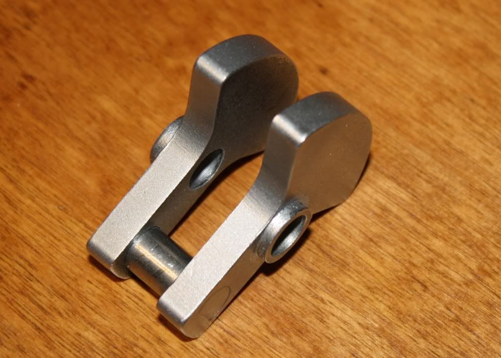
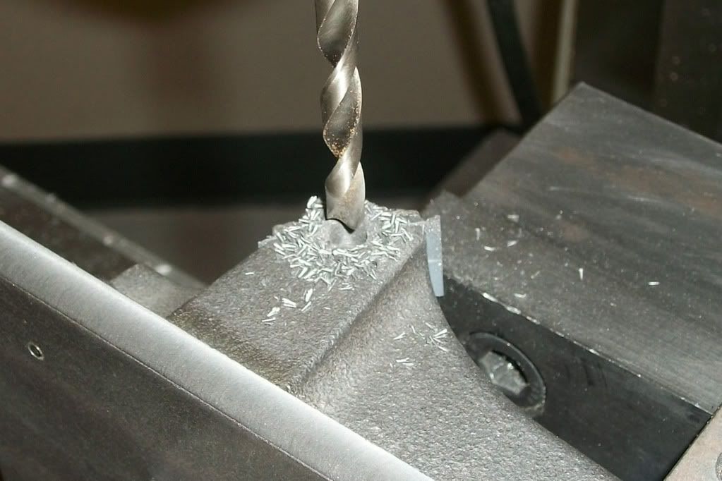
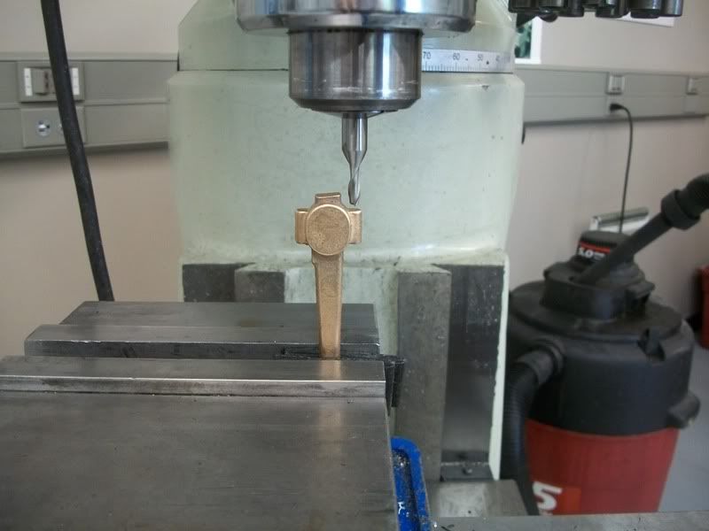
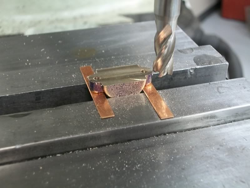
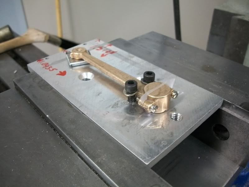
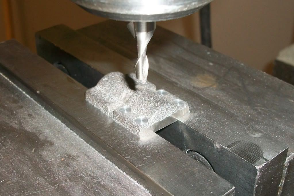
I wanted the crank to have counterweights because I think it makes the motion more interesting. The journal is pressed into a "D" shaped hole, and then I drilled and pressed in 1/8" pins radially after making some adjustments to get the sides as parallel as possible.
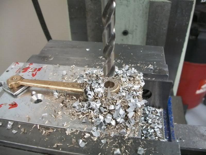
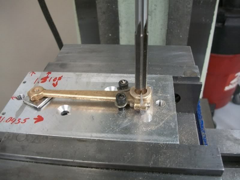
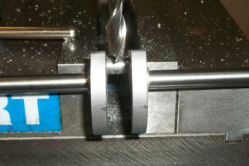
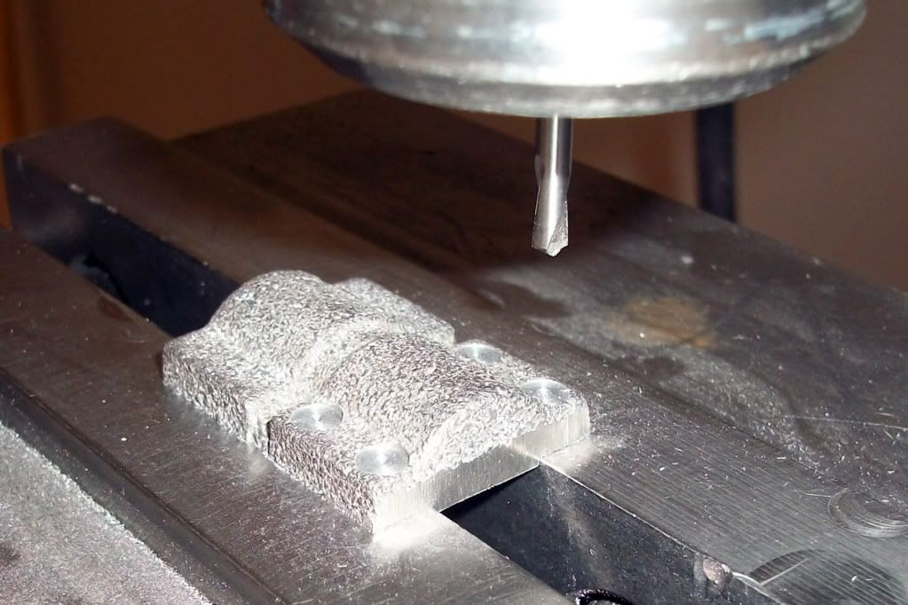
Tomorrow I'll put a 6" piece of drill rod through the center hole, and pin it in place. I plan to spin it on the lathe to see how true it is, and make any cleanup passes that I feel are necessary. Then I'll cut out the center section of the drill rod to finish the crank.
I wanted the crank to have counterweights because I think it makes the motion more interesting. The journal is pressed into a "D" shaped hole, and then I drilled and pressed in 1/8" pins radially after making some adjustments to get the sides as parallel as possible.
Tomorrow I'll put a 6" piece of drill rod through the center hole, and pin it in place. I plan to spin it on the lathe to see how true it is, and make any cleanup passes that I feel are necessary. Then I'll cut out the center section of the drill rod to finish the crank.
Last edited:


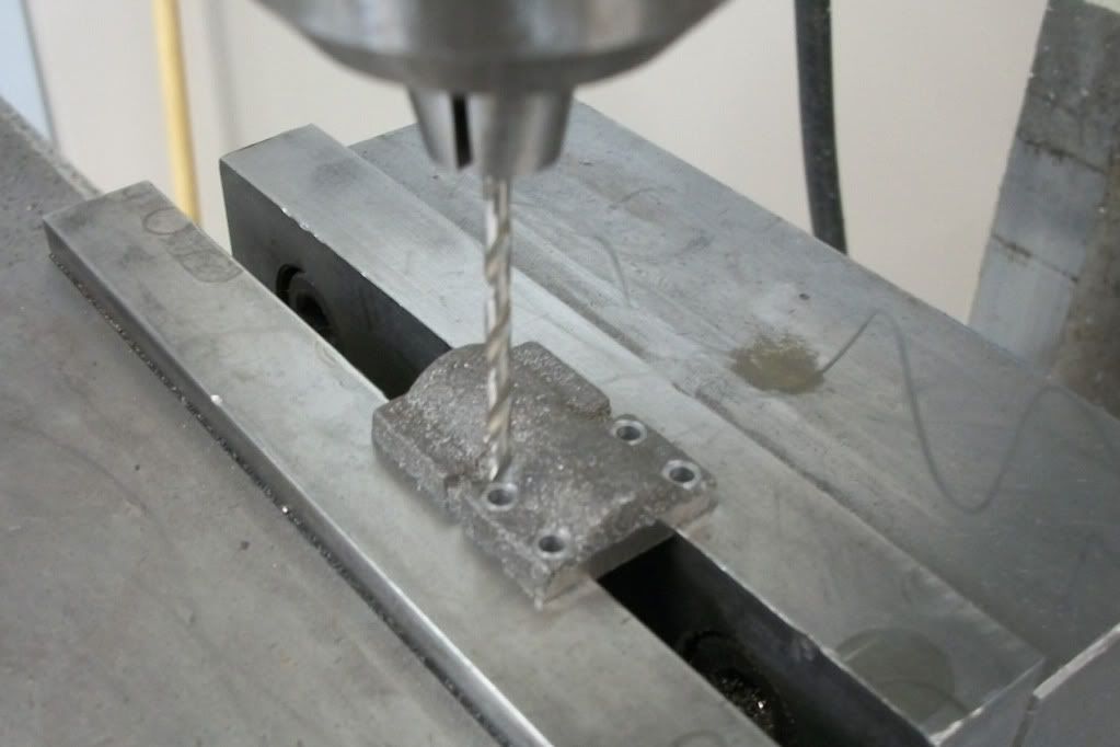
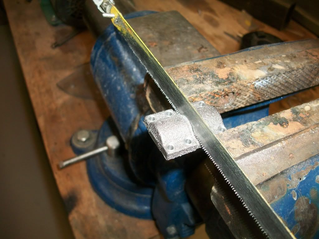
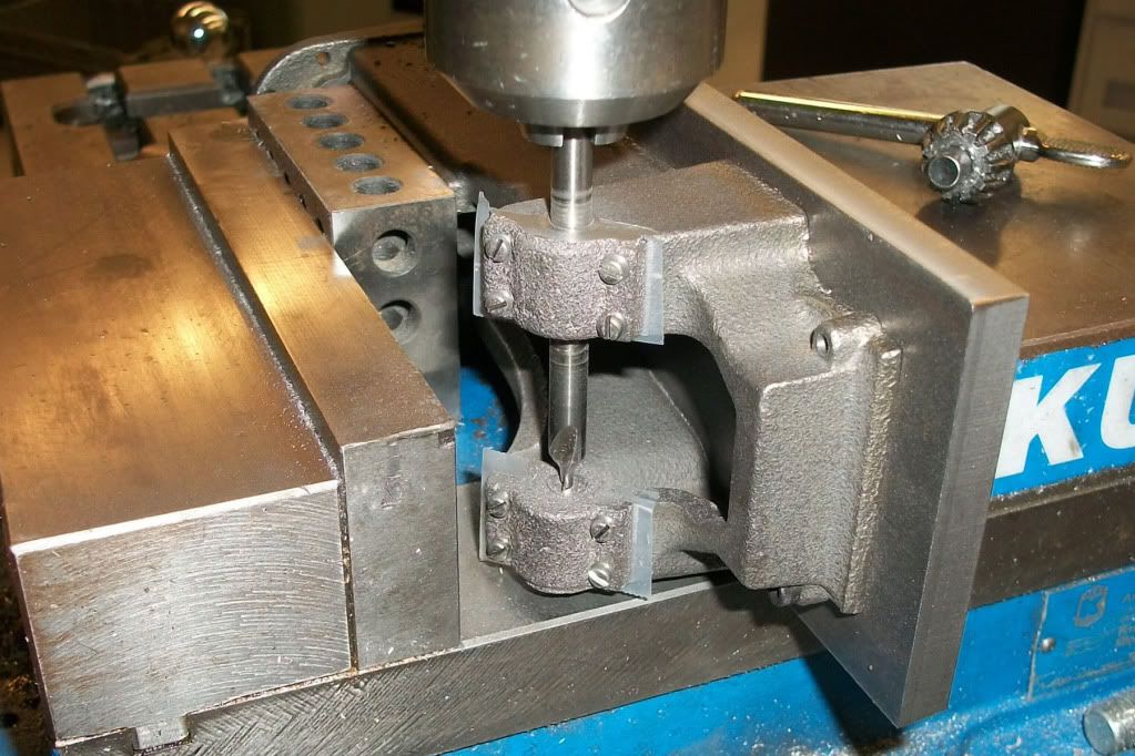
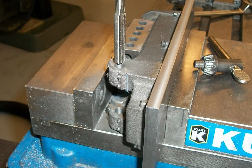
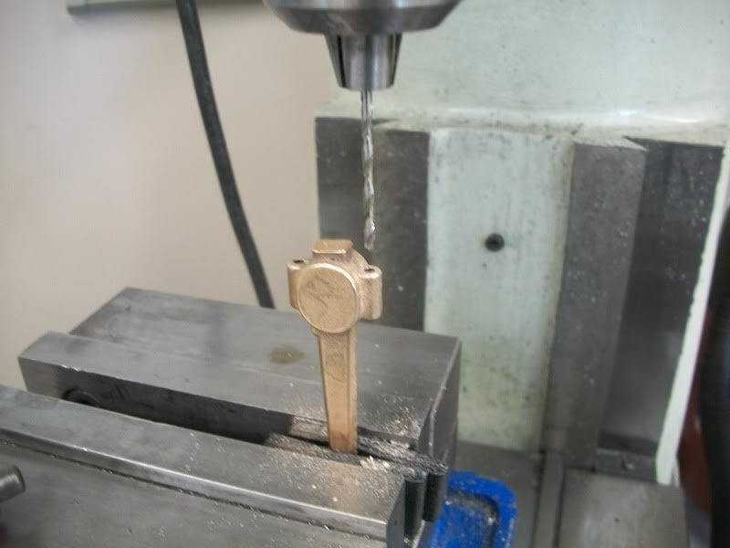
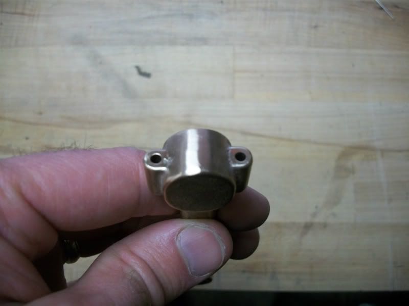
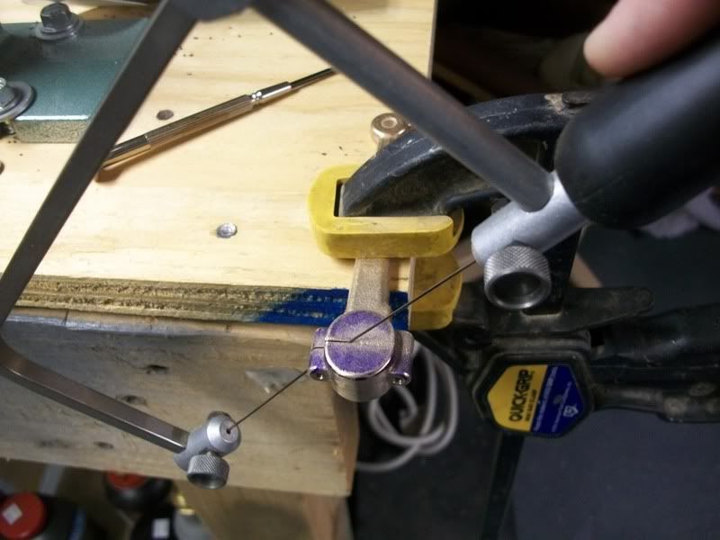
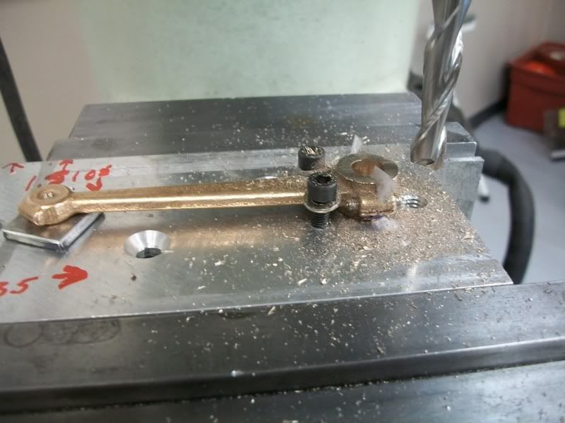
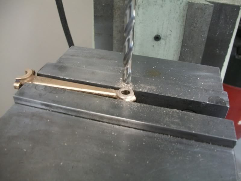
") so here I am separating the two bearing caps with a hacksaw.
so here I am separating the two bearing caps with a hacksaw.