PM Research No. 1 Build

Home Model Engine Machinist Forum

Help Support Home Model Engine Machinist Forum:

This site may earn a commission from merchant affiliate links, including eBay, Amazon, and others.

rhitee93

Project of the Month Winner!!!
Project of the Month Winner
Joined
Mar 13, 2012
Messages
583
Reaction score
62
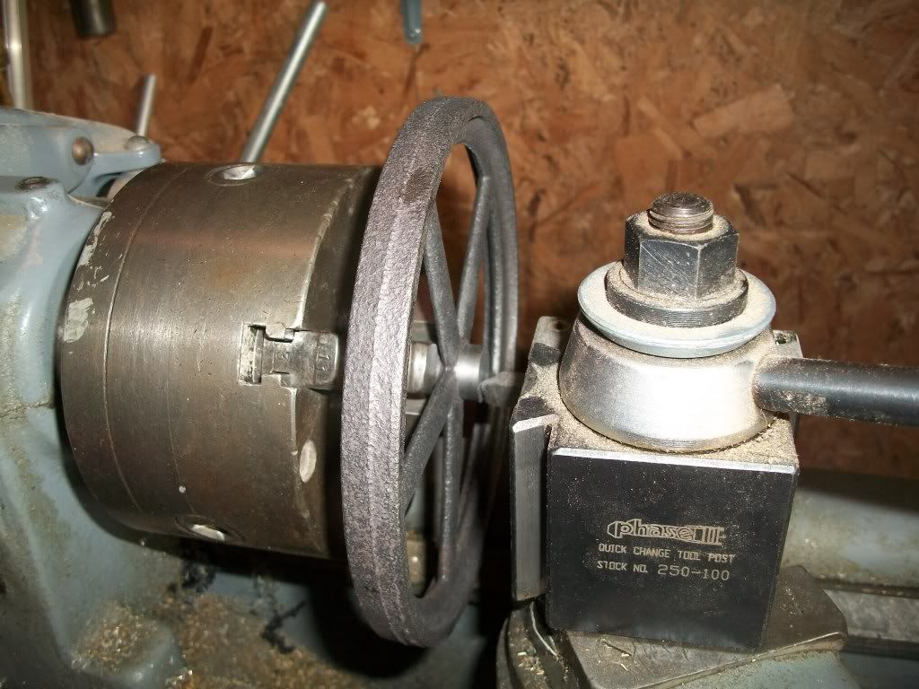
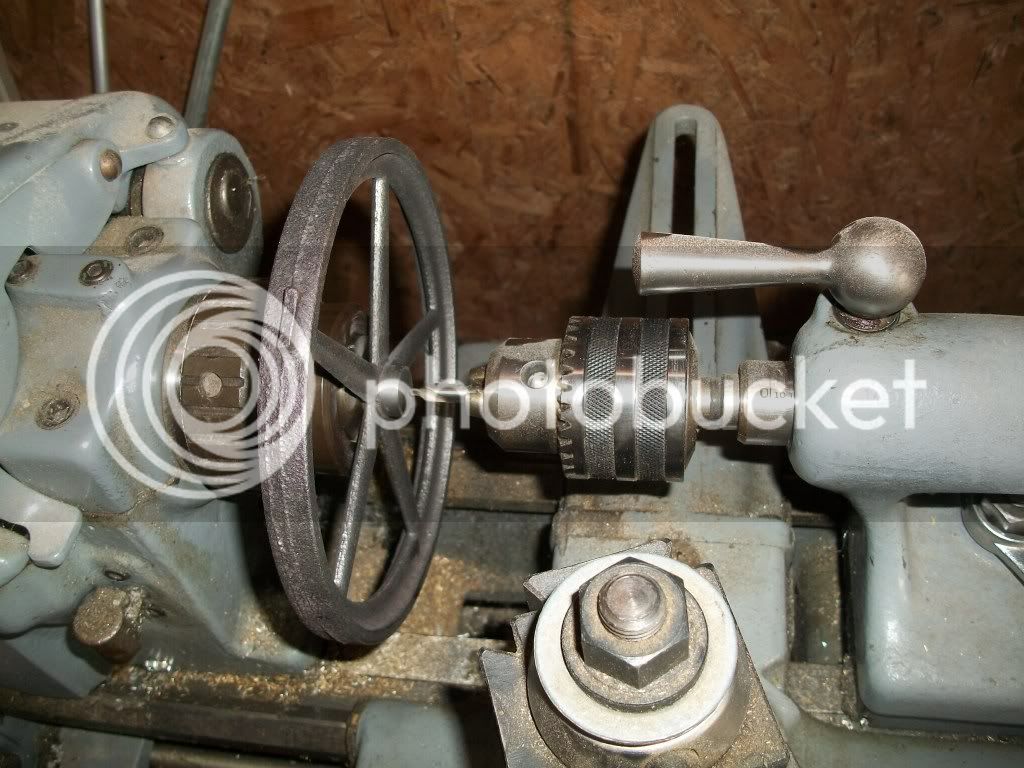
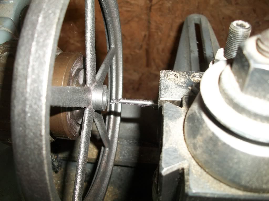
A build log for a PM Research No.1 engine.

Hi all, I thought I would start a thread to share my build of a PMR #1BI from a casting kit. I am actually about 10 hours into this build so it will take me a few posts to catch up.

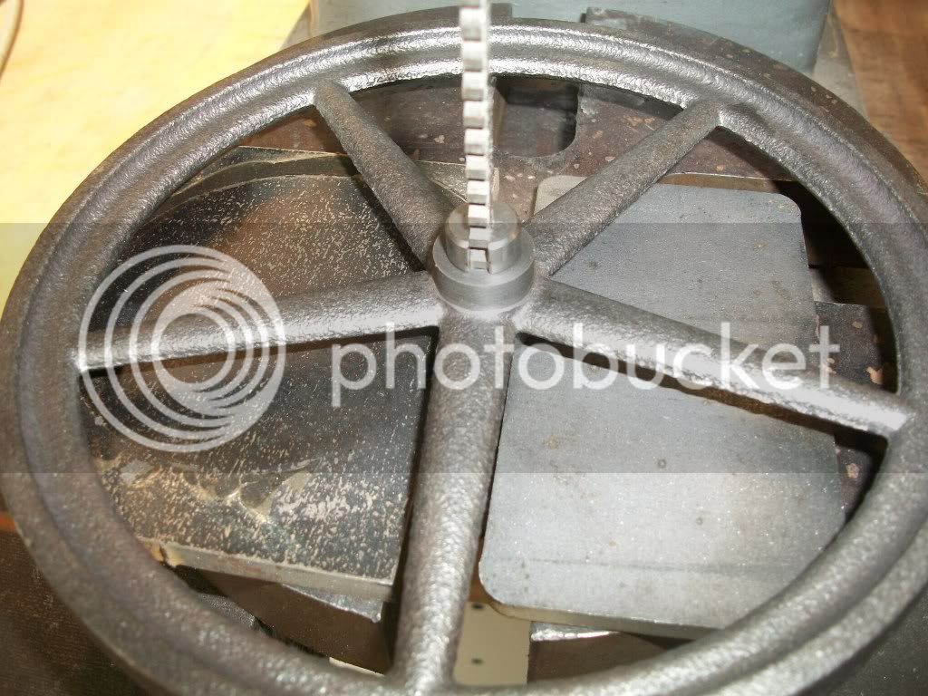
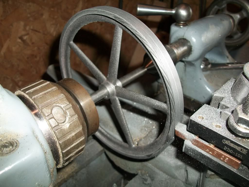
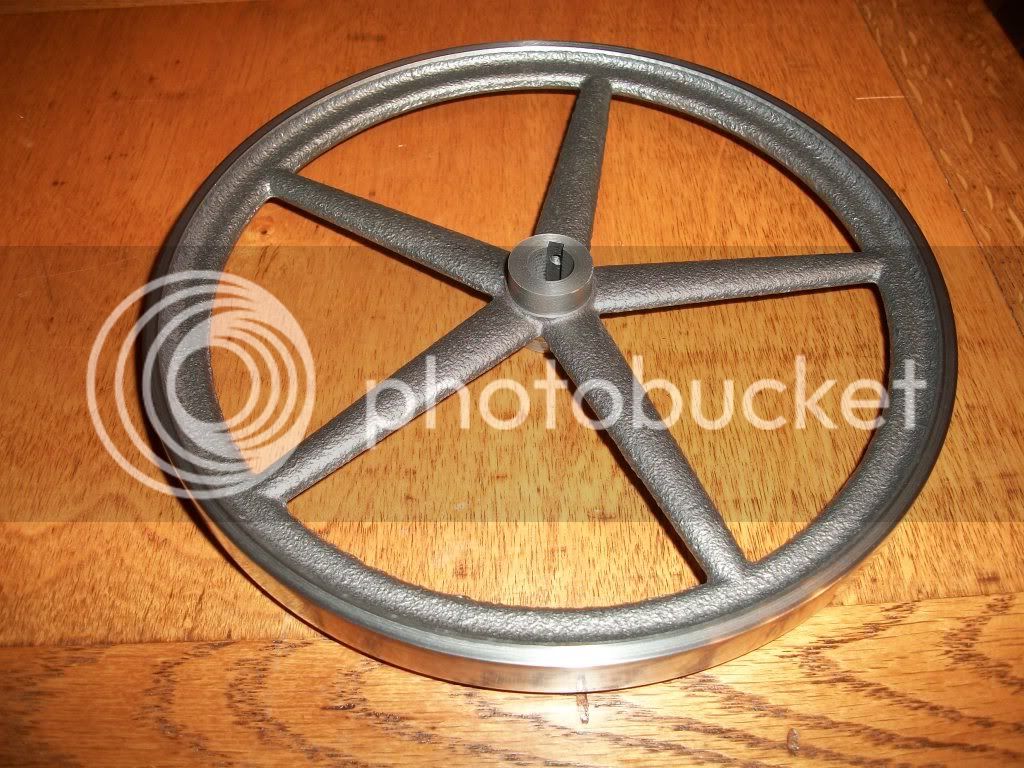
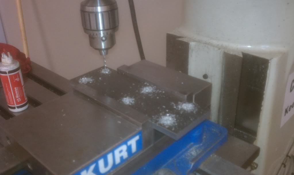
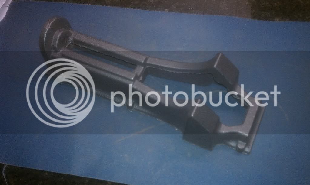
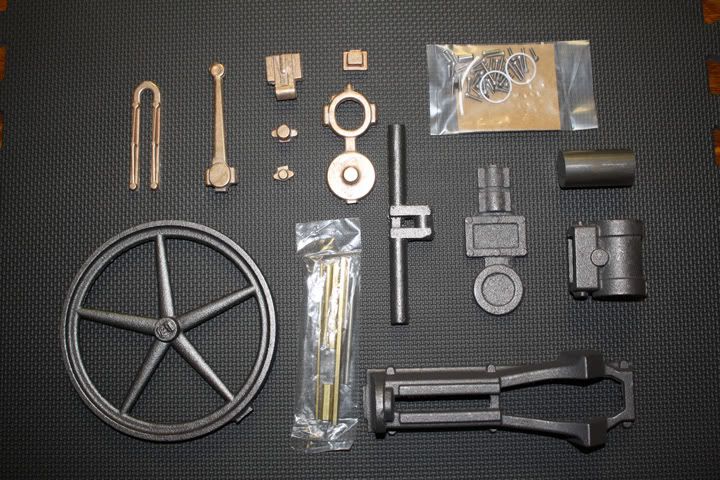
First, here is a shot of all the castings that come with the kit. I have only built one engine from castings before, so I am not a expert at quality, but for the most part these seem pretty good. For reference, the flywheel will finish out at over 6", and the bore will be 1".

KitParts.jpg
 
Last edited:
I decided to start working with the flywheel for a few reasons. First, it is the easiest to plan out the order of the machining operations. Second, it was the one part that I was afraid would be a bit of a mouthful for my 10” lathe so I wanted to try it out to see what issues I would have. Third, it is the fastest significant part to complete, and I am a sucker for instant gratification.

With my particular selection of lathe chucks and jaws, the best approach for me was to use a 3-jaw to hold onto one side of the hub while I made the cleanup passes on the other side. I would have preferred to hold onto the rim, but my 6” chuck didn’t have enough reach to get out that far with outside jaws, and I couldn’t get the inside jaws to clear the spokes.

The 3-jaw didn’t have much material to hold onto, and the casting surface has some draft to it so the flywheel does not register very true if you just tighten down the jaws. I used a dial indicator to measure the run out at each spoke and just kept moving the wheel within the jaws to get it as even as possible. I was able to get to +/- 0.010” at the outer tips of the spokes. I used the spokes because there was a lot of variance in the rim width.

Machininghubface.jpg
 
Last edited:
I turned down the first side of the hub to fit into an 11/16” collet. This way I could get a better grip on the flywheel when I bored the hole for the shaft. Here you can see the flywheel chucked up in a 5c-collet. The hub has been completely cleaned up now, and a center drill is being used to locate the initial drill.

Centerdrill.jpg
 
Last edited:
After drilling an initial hole, I bored it out to size. Boring is my absolute favorite lathe operation, and this cast iron machined quite well. This is also where I deviated from the plans a bit. (Hey, I made it all the way to 3 operations before I broke the rules. That has to be a record for me!) I decided to broach a key way through the hub. I did this for two reasons. First it would let me use a surrogate shaft to turn the outer rim, and second the big 6.5" flywheel won't rely on just a 5-40 grub screw to hold it in place while the engine is running.

Boretosize.jpg


Broachkeyway.jpg
 
Last edited:
I don't have this one yet, but hope to some day so will be watching how you make out. Looks like you are off to a good start here.
 
I will follow alone also. I would like to see how PM,s casting kits turn out. I bought the Dynamo kit I really liked it. You have a good start so far.

Regards Don
 
Thanks for doing this. I am taking notes. I have a PM #1 and am getting ready to start it.
 
I'll be tagging along also. Looks like an interesting and fun build. Thm:

Regards,
Rudy
 
I have a #1 waiting in the wings too so will be following along with interest. I like the idea of adding the keyway to the flywheel bore. Keep up the nice work and pictures!!

Bill
 
Thanks for the interest guys! Here are the last flywheel pics. You can see the flywheel mounted to a temporary shaft and back in the lathe. I don't have a dead center, so I held one end of the shaft in a collet and the other on the live center. I had to use light passes to keep the chatter down, so I didn't have much of a problem with the shaft getting pushed back into the collet. (Which can be an issues with this setup)

MachineRim2.jpg


The rim polished up pretty well, but I will probably go after it a bit more. I have some meager nickel plating abilities, and have been considering plating the wheel before painting so that the rim would have the nickel look. I'd probably have to invest in a copper plating kit first so I can build up the pores in the casting surface with successive plating/polishing operations.

I already have most of the engine base machined. I'll start on those pics next...

FinishedFlywheel.jpg
 
Last edited:
That turned out well Brian...I was worried as to the chattering on that flywheel given its small mass vs. diameter. Looks great!!

Bill
 
When I was doing a Stuart Beam flywheel, I tried doing it on a shaft like you are here, but I wasn't able to avoid chatter marks on the sides. I ended up bolting it to a faceplate, which was much more rigid and avoided the chatter.

Good work here on the PM kit though. The Al version of this kit was my first "from castings" attempt, and I made a real pig's ear out of it ;D

Simon
 
Yeah, the flywheel was singing a bit with this setup. I had the lathe running in back gear. I don't know the speed, but probably around 150 rpm. I had some chatter marks on the sides but was able to clean them off with a HSS parting tool by just using the corner of the tool.

The hard part was getting to the point that I had an uninterrupted cut. there was probably 0.050" run out on the sides because the flywheel wasn't flat. It was a booger to get past.

I'll try to post more tonight...
 
Brian

I will be following your build also

Vince
 
I decided to follow an approach I saw on another build log, and machine the frame of the engine while it was attached to a reference plate. I squared off the edges of a 9"x3" piece of 3/8" steel bar stock and drilled the nominal hole pattern for the mounting holes in the engine frame. I knew that the holes probably wouldn't line up perfectly with the pads on the frame, but it looked like they would be close.

I used 1/8" dowel pins in two opposing corners and reamed these holes in the frame to match. this was probably overkill, but it seemed like the right thing to do. Here is a pic of the plate after drilling. The DRO on the mill makes this easy.

DrillingMachiningPlate.jpg
 
Last edited:
I struggled to find an elegant way to flatten the bottom of the frame. In the end I just used a long strip of 80 grit sand paper on a level concrete floor. After about 5 minutes, I had the bottom leveled. I finished up with a piece of 220 emery cloth on a piece of polished granite someone gave me from a counter top project.

FlateningBottomofBaseCasting.jpg


Then I clamped the frame to the mill table over a piece of flat plastic stock and "Indexed" it in so to speak so that a bolt pattern that would match the reference plate was as well centered over the mounting pads as possible. As you can see, the screws aren't perfectly centered on the pads. It doesn't really bother me, but if I had it to do over again, I would modify the pattern in the reference plate from the prints slightly so that there would be a better match.

CenterdrillingBaseMountingHoles.jpg


Overallbase.jpg


Tomorrow I will show some of the maching steps for the frame...
 
Last edited:
Very interesting approach, looks like you are on your way. Keep us posted with your photos. One of the interesting part of this forum is guys telling us about there mistakes so the rest of us newbies can learn what not to do, and some of the guys tell us how to do it better.

Don
 
Looking REAL good so far. Please keep the pictures and descriptions coming, I will be following along.


tom
 
Looking good Brian, still following along with interest here.

Bill
 
I like the idea of using a reference plate. That really helps get around one of the most difficult issues with castings.
 

Latest posts

Back
Top