PM Research No. 1 Build

Home Model Engine Machinist Forum

Help Support Home Model Engine Machinist Forum:

This site may earn a commission from merchant affiliate links, including eBay, Amazon, and others.
smfr said:
I like the idea of using a reference plate. That really helps get around one of the most difficult issues with castings.

I wish I had thought of it on my own, but I saw it on another build site somewhere. I'll try to post some more pics tonight. the last couple of evenings have been busy with kid activities :)
 
Here is a shot of the first cuts on the base. I decided to start with the rails for the cross head. After that it is easy to measure the height of the rails relative to the reference plate, and therefore to machine all the other surfaces by indexing in off the plate.

Firstpass-cleaningupthecrossheadrails.jpg


While I was setup with the centerline of the engine defined, I also machined the opening between the crank shaft bearing blocks to size. the prints leave a lot to interpretation here. They give you the finished opening width, but don't really say how far forward and back to extend the machined surface. I may have to revisit this if things don't fit.

Overall, it looks like I have the frame about 0.020" off to one side of what would have been the true centerline of the casting. There should be plenty of material to work with, but if you look close you can tell.

Finishedbearingblockinside.jpg


After I had the rails machined, I clamped the reference plate to an angle plate on the CNC mill at work. I used it to spot face the surface for the inboard head, the bolt pattern for the cylinder, and the stuffing box holes. I know it is more conventional to use the mating parts to locate these holes in the frame, but with the DRO on the conventional mill and the CNC, I think (at least I hope) I can make all the parts match up.

Startingtospotface.jpg
 
Last edited:
Here is a shot of the front of the frame with the complete bolt pattern for the cylinder, and stuffing box. You can see how the margins on the spot face come up just a bit higher on one side. More evidence that I didn't have the casting on it's true center when I started cutting.

MachinedCylinderMount.jpg


Machining the tops of the bearing caps was an interesting challenge. The print gives you the X-Y location of the centerline of the crank shaft relative to the top of the cross head rails and the forward surface where the inboard head will rest.

This is easy enough to locate when you have the frame on its side. however, the bearing caps get machined at a 45-deg angle with the frame upright, and the only reference on the print is that the caps get machined to the centerline of the crankshaft. You could do this with the frame on it's side, but you are supposed to create a recess for the bearing caps, and that wouldn't be possible unless you machine it top up.

I scratched my head for a while, and after an hour of goofing around with some trig, I figured out how far to move the centerline of the cutter along the X and Z axis to get to the centerline of the crankshaft when the reference plate was in the vise at 45 degrees.

As a sanity check, I mounted the frame in the mill as if I was going to drill the crankshaft hole, and touched the surface of one bearing stand with a center drill. If the math was right, I would cut right through the center of the drill spot. I'll be darned if it wasn't right on the spot! :big: You can see the 1/2 of the dimple on the right stand. I scanned my page of calculations for those who like to read bad handwriting.

The finish on the bearing stands is much better than it looks in the photo. The flash makes it look rough.

BearingBlockSurface.jpg


View attachment trig.pdf
 
Last edited:
This all looks great! I'm learning lots of things I can use on the second set of PM Research castings that I've got :)
 
Here is an overall shot of the frame. I forgot to post it last night The only major operation left is to drill/ream the crankshaft hole. I'll get to that once I machine the bearing caps. I'll do a better job of cleaning up the mold lines when I get closer to assembly. Still a long way to go before I need to worry about that :)

Overallbase.jpg
 
Last edited:
Still looking very nice Brian. That base is just about done and I suspect thats one of the more difficult parts to machine. Nice pictures of what your doing along the way as well!!

Bill
 
Good work Brian I am still following with isn't rest. I was wonder how you were going to do your centerline for he crank and cylinder good job.

Don
 
I put the base aside for a while so I could start on the cylinder. (I like to get the hard parts done first)

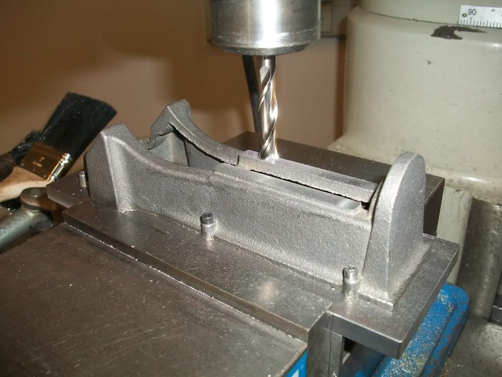
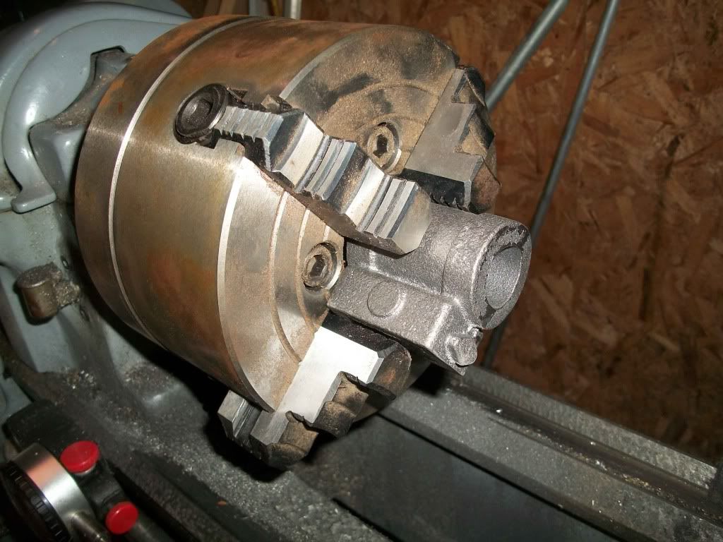
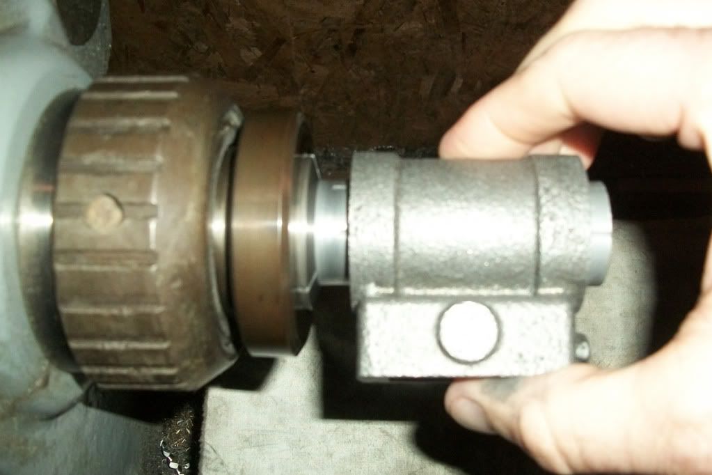
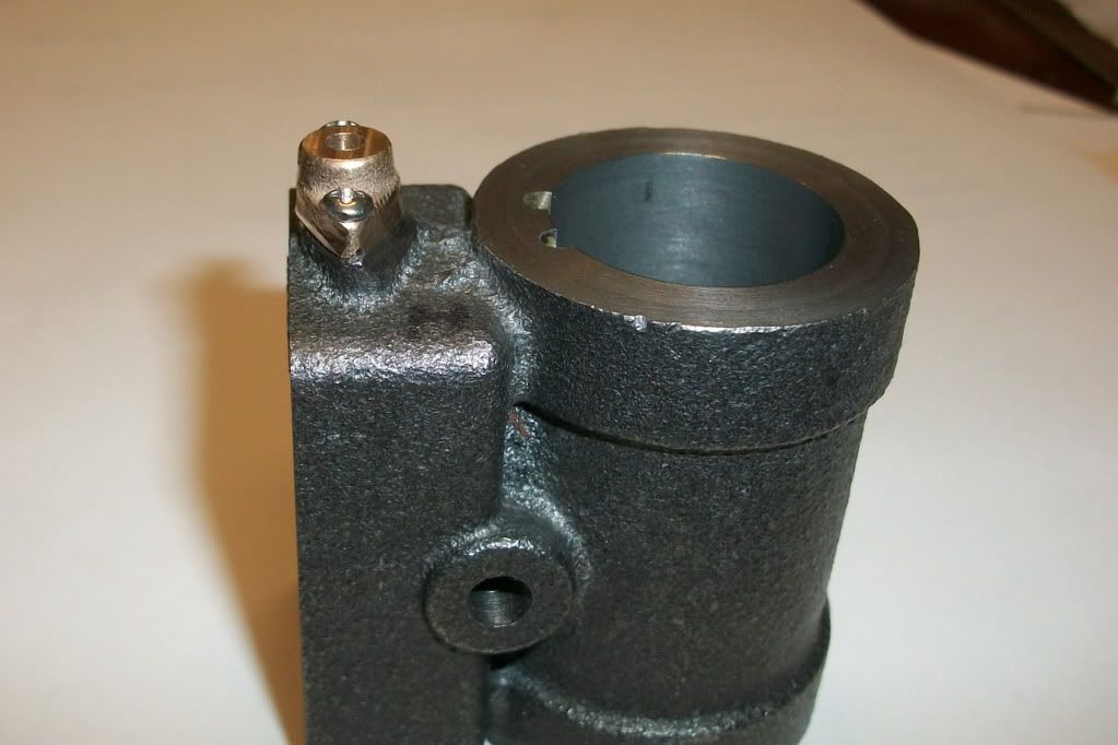
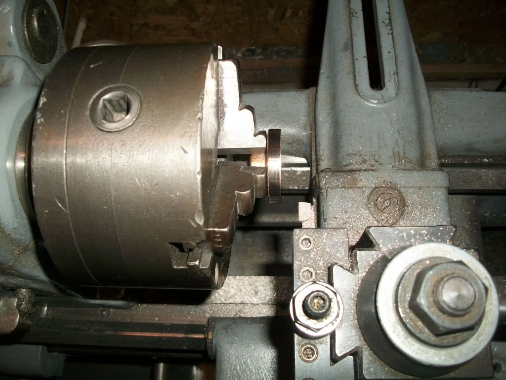
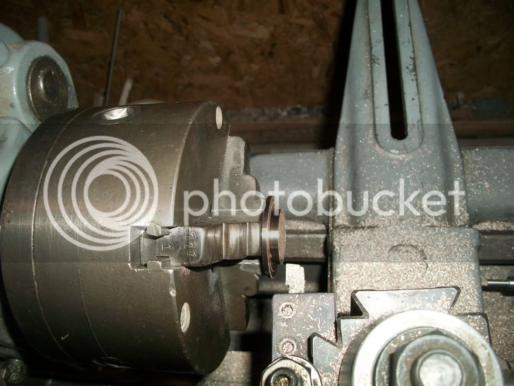
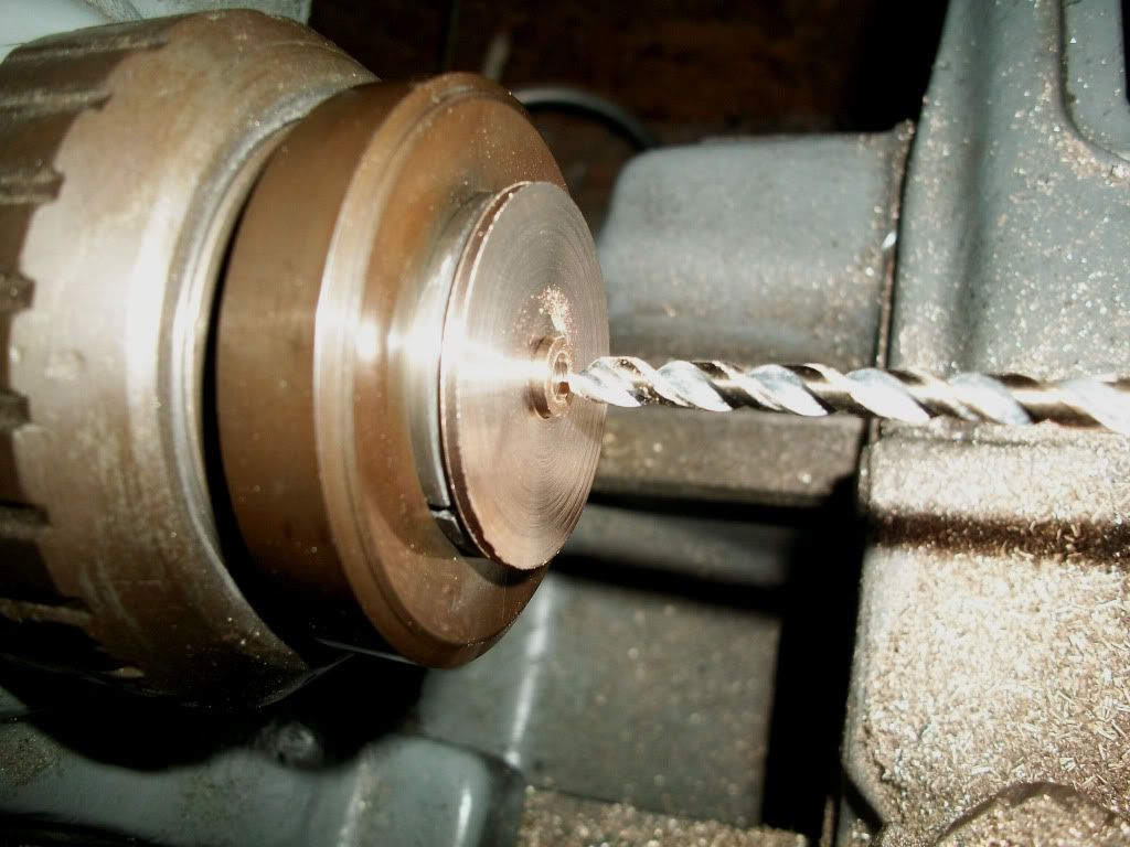
The first pic is getting ready for the bore. I decided to hold the raw cylinder casting in a 4-jaw chuck, and machine the bore first followed by the inboard head surface in the same setup. This should maintain the important alignment between the path of the piston and the bore of the cylinder.

I haven’t done a lot of 4-jaw work but I was able to get the cylinder “Centered” around the rough cast bore pretty well. The hole is a bit egg-shaped as cast, so it takes some interpretation. This made sure the inboard opening was running on center, but how should I make sure the entire axis of the bore is on center?

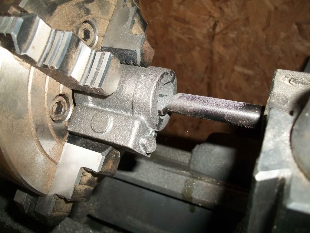
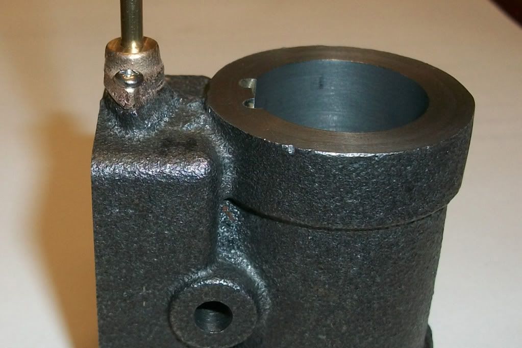
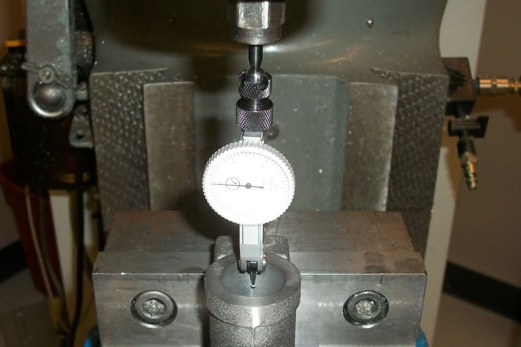
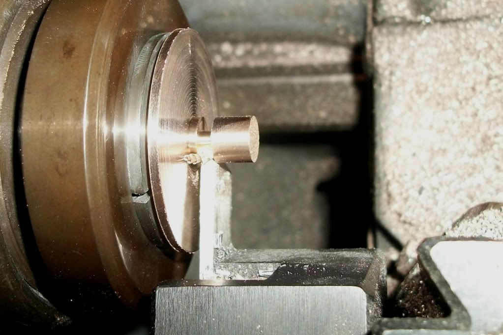
I checked the alignment to the axis of the bore by running the test indicator in and out of the bore as far as I could reach. The reading was dead on, but I must have goofed up because the end result isn’t quite right. The bore isn’t as well centered on the outbound end. Oh well, my engine will just be looking a bit to the left…

Setuptoborecylinder-1.jpg


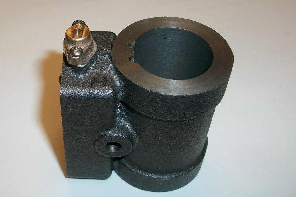
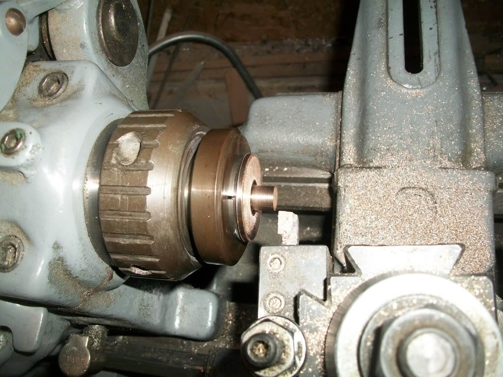
I used the stoutest boring bar I had that would fit, and had no trouble at all with chatter. However I ended up with about 0.002” of taper. The odd thing is that it is the end closest to the lathe headstock is the larger end. Not what you usually get due to tool flex, so I suspect it is a measure of the wear in my lathe bed. I have managed to get most of the taper out, but it will be a few posts before I catch up to that step.

When I was done I cleaned up the rust on my chuck. I had it sitting under an oily rag, but haven't used it in a couple of years. Dooh! ::)

BoringCylinder-1.jpg


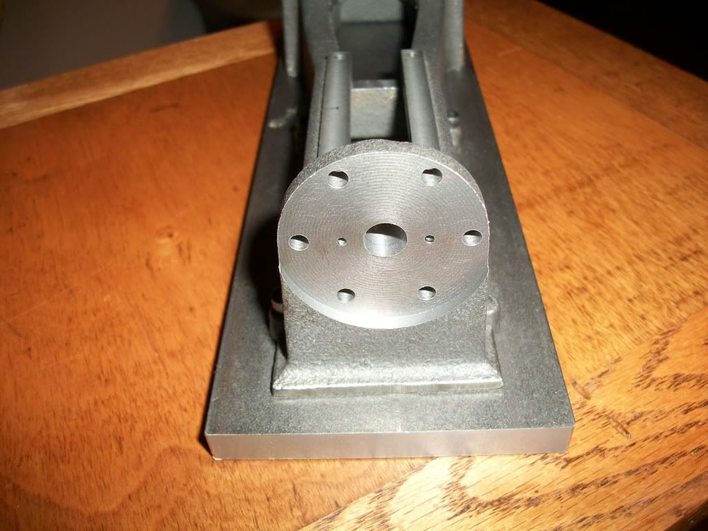
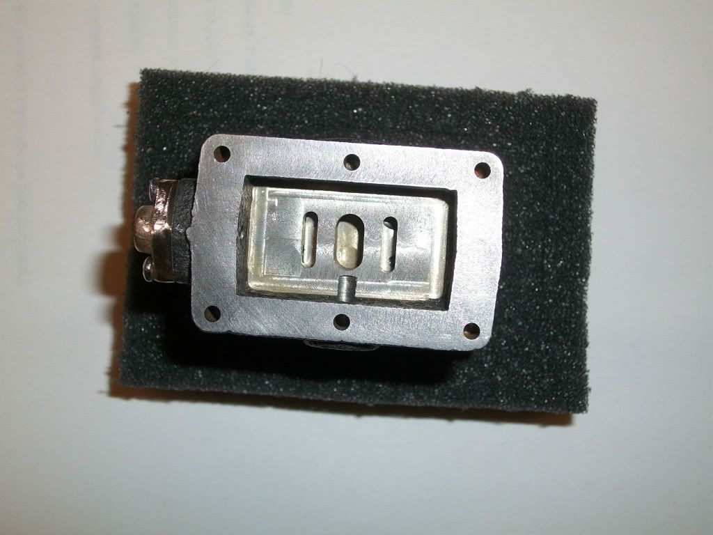
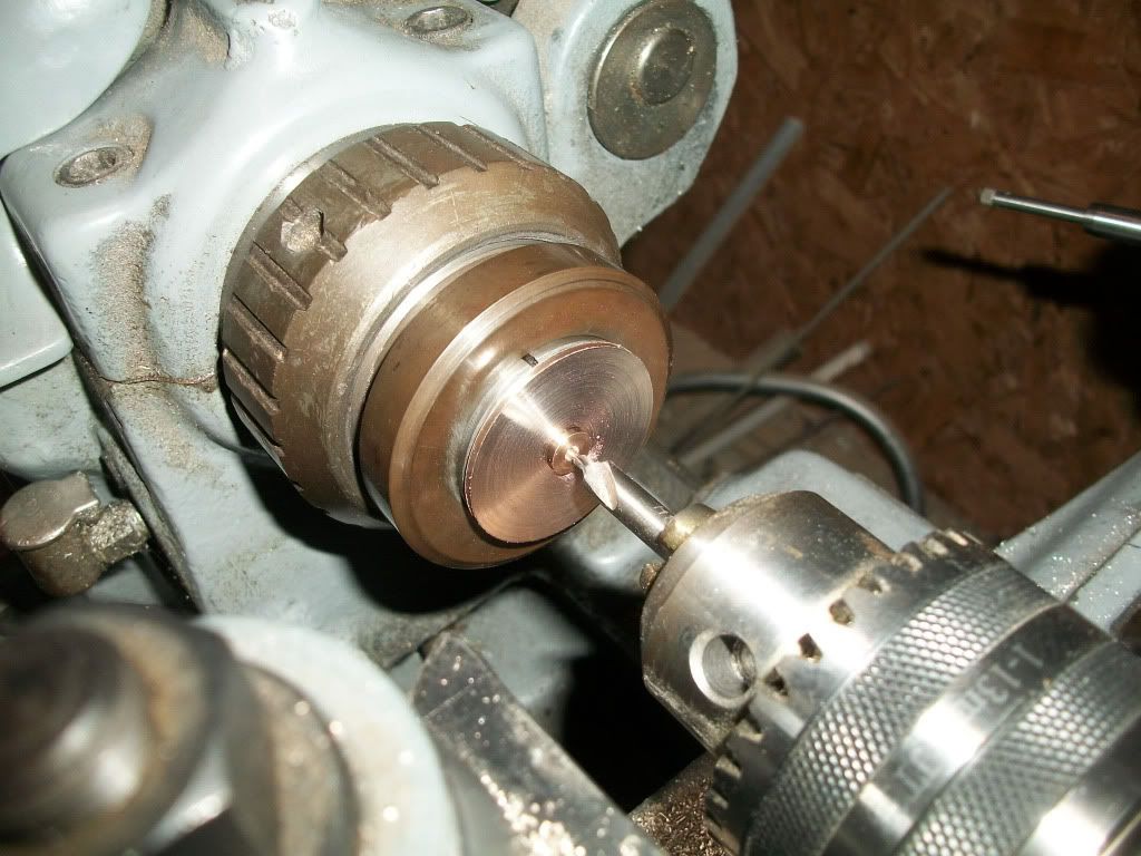
Somehow I managed to not get a pic of facing off the inboard end. Not too exciting to see, but I wanted to point out that his is where the prints may lead you astray.

The print indicates that this should just be a cleanup pass. Since I didn’t think to compare the length of the casting the specified finished length before I chucked it up, I was afraid to take off too much material. Unfortunately just cleaning up the surface results is a cylinder that will be way too long. You really have to take close to 0.100” off each end to get the bore to the correct length.

I can’t take enough off the other end without cutting into the steam chest. So I am stuck with a bore that is almost 0.100” too long. I may increase the length of the piston and piston rod to compensate so I don’t have so much dead space at the ends of stroke.
 
Last edited:
Here I have put the cylinder in the mill vise against the newly machine inboard end. This allowed me to machine the face of the steam chest flat. I also did the cleanup pass for the valve surface of the steam chest. I did most of this with a larger cutter, but came back in with an 1/8” endmill to clean up the corners a bit.

FacingOffSteamChest.jpg


CleanUpChestCorners.jpg


Once the opening of the steam chest was flat and reasonably perpendicular to the inboard face, I flipped the part around and faced off the outboard end of the cylinder and removed the unused packing gland boss. I believe you can assemble this kit with the steam chest on either side or vary the exhaust/supply line locations by selecting which boss you use.

facingOutboardEnd.jpg


You can see here how much more material was removed from the outboard face than the inboard. The cylinder is still over 0.100" too long, so the inboard end should look more like the outboard.
 
Last edited:
The next step was to machine the valve ports and bolt holes in the steam chest. I should have done this when I had it setup before, but I was focused on getting the cylinder ends right, and didn’t think about it. Here you see the supply port and exhaust ports being machined. Then I center-drilled and drilled the bolt holes for the cover. Once again, these are supposed to be located by the cover, but I am confident that I can make the cover match the holes. (We’ll see…)

Milling the exhaust port:
MillingExhaustPort.jpg


Milling the supply ports:
MillingSupplyPorts.jpg


Center drilling and drilling the steam chest bolt holes:
CenterdrillingBoltPattern.jpg


DrillingBoltPattern.jpg


Sorry about some of the photos. I don't want to take my good SLR into the shop, and this little point and shoot is struggling to focus on the right points. I can't see they are out of focus until I load them on the computer.
 
Last edited:
I was a bit bugged by the taper in the bore. I have a 1” ball bearing that I used as a gage ball, and it was too tight to pass all the way through the cylinder.

I made a lap from a piece of 1” aluminum tubing by mounting it in a collet, and using a lathe like a shaper to cut groves along it’s length. Using some 600 grit aluminum oxide paste, I was able to get the bore to even up a bit. I rested the part against the tool post to stop it from rotating. I could then use the carriage to move the part back and forth. This way I didn’t have to hold the part in my hand.

AluminumLap.jpg


Now, if I use the heal of my hand to plug up one end of the cylinder, the gage ball will sit on the cushion of air trapped in the cylinder until I take my hand away.

Looking through the bore, I can see where the lap has worked, and where the bore still has the machined finish. Since I can machine the piston to size, I may go back to the lap and try to even out the surface. I got a great finish with the boring bar, but the lapped surface is much smoother.
 
Last edited:
I forgot to take a pic of the setup for drilling the steam passages from the ports in the chest to the ends of the cylinder. It looks scary on the drawing, but it is easy. I set the 20-deg angle by using one of those magnetic gravity protractor deals. Then spot faced the location with an 1/8” end mill followed by the 1/8” drill.
 
Here is another spot that I goofed up on:

The packing gland for the valve rod is located 0.250” above the “Floor” of the steam chest. This floor is located 0.438” from the top surface of the chest. However, when I did the cleanup pass for the top surface, I didn’t take off enough material. The end result is that the floor is a little further away from the centerline of the cylinder than the designer had intended. This causes the gland location to not be centered well within the boss cast into the steam chest.

InboardPacking2.jpg


Had I been thinking clearly, I would have gone back and taken another 0.080” off the top surface and then the floor of the chest. I didn’t do this because I didn’t want to have to try to relocate and then deepen the steam ports. However, I had already drilled the steam passages and they connected with the ports just fine so they wouldn’t have needed to be enlarged. Oh well… …lesson learned.

I did come up with some camouflage. I used a carbide bur in a dremel to take down the overhanging edges. Then borrowing the dithering concept from Ramon’s Table Engine build, I used an electric engraver to hide the ground surfaces. I need to touch it up a bit more, but it won’t show too bad once painted.

iboardpackingafter2.jpg


InboardPackingDithered2.jpg


One lasting result of this error is that the steam inlet hole, when drilled in the center of the boss, does not clear the steam chest floor. I may have to see if I can fill this gouge somehow…

ChestFloorGoof.jpg
 
Last edited:
Now it was time to drill & tap the cylinder bolt circle. First I indexed in on the bore of the cylinder. After doing this, I can see why people pay more for test indicators with dials that always face forward.

IndexingInCylinderBore.jpg


Taking a lesson from the “Drilling Holes” thread here, I bought a spot drill to locate the holes.

SpotdrillingHeadBoltCircle.jpg


Then drilled them, and finally tapped them 5-40 using a tap handle that can be located in the mill arbor.

DrillingHeadBoltCircle.jpg


TappingHeadBoltCircle.jpg


I opted to trust the readout on the mill, and my ability to index rather than locate these holes from the heads. In the next post I’ll see if the holes line up with those in the frame. If I’m not back in a day or two, you’ll know the answer :)
 
Last edited:
You are really getting after it Brain. Looking good so far keep the photos coming.

Don
 
Next up is the inboard head. To get started, I chucked the blank up in the 3-jaw and cleaned up the outside diameter.

inboardheadfirstpass.jpg


Then I turned down the boss for the cylinder size to match my cylinder. I don’t have a DRO on the lathe so I use a dial indicator for steps like this. You can just see the stem of the indicator in the lower right corner of the pic.

inboardheadcylinderboss.jpg
 
Last edited:
Once the cylinder side boss was done, I could flip the part around and hold onto the boss with a 1” collet to machine the other side.

inboardheadglandboss.jpg


There is a fair amount of material to remove, and I ended up just parting off the excess for the packing gland boss.

inboardheadpartingoff.jpg


Then I just centerdrilled and drilled the through hole.

inboardheadcenterdrill.jpg


inboardheadthroughhole.jpg
 
Last edited:
To locate the bolt circle, I made a simple fixture on the mill.

Using a scrap piece of aluminum, I milled a pocket that was a nice fit for the cylinder side boss. I added an 8-32 tapped hole in the center.

inboardheadBCfixture.jpg


This let me hold down the head so that the center was at a defined zero point so that drilling the pattern was simple.

inboardheaddrillingboltcircle.jpg


inboardheadcomplete.jpg


Yeah! It Fits :)

testfit-1.jpg
 
Last edited:
Nice to see how much progress you are making Brian, and its coming together very nicely too. When i first saw this engine years ago it wasnt one of my favorites, but the more i looked at it the more elegant looking it became. One of these days I hope to get mine made so thanks for doing this build log!!

Regards,
Nill
 
Thanks Bill, I have to agree with you on the looks of the engine. When I built my #3 years ago. I thought this one was rather awkward looking. However, this time around I envisioned it on a nice base with a flywheel pit, and it seemed much more graceful.

I really like these horizontal engines. I'd like to build a Victoria some day, but have been scared off a bit by reports of poor castings.

Then again Ramon's Table Engine build has really inspired me as to what is possible without castings!
 
Back
Top