PM dynamo question

Home Model Engine Machinist Forum

Help Support Home Model Engine Machinist Forum:

This site may earn a commission from merchant affiliate links, including eBay, Amazon, and others.

Rolland

Well-Known Member
Joined
Jul 2, 2009
Messages
108
Reaction score
25
Location
Camp Verde, AZ
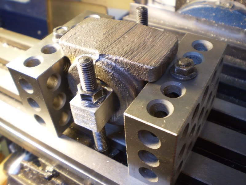
I have picked up the dynamo kit and had a question on machining. Where did you start I was thinking on starting on the bottom of the frame and measuring off that once it is flat and the mounting holes are drilled. any suggestions would be appreciated.
 
What I did was to turn the casting bottom up and put 2 tool bits as parallels under the mounting lugs across my vise jaws. This insured that the lugs would both be parallel. I then machined the the bottom to thickness. Then after getting a good center point on the bottom I very accurately drilled and reamed the four mounting holes. With this done I then put 2 ground pin in the holes that would be the upper holes if the main frame were to be placed vertical with the armature axis vertical. I then clamped the casting in my milling vise with the 2 pin resting on the top of my vise jaws. Now I took a cut to clean up the casting face, then without moving the cutter vertically, move the cutter to the side. Now I flipped the casting so the other side was up moving the pins to the other 2 holes and again rested these pins on the vise jaw and clamped it there. Now without moving the cutter made another clean up pass, and again without moving the cutter vertically move it out of the way. This made the casting true and centered. Now all I had to do was to measure the casting, subtract the finished dimension, and move the cutter down 1/2 of the difference make a cut, don't move the cutter vertically, turn over the casting moving the pins back to the other holes and make the last cut. Now the casting is to the final dimension.
Next the boring. I held the casting as before resting on the vise jaws with the 2 pins. I then used an edge finder on the outsides of the 2 pins to find the center, and then used the edge finder to find the edge of the bottom of the casting and moved the required amount to find the center of where the hole would be bored for the armature.
Here are a few Pics. These are not the pins that I used ( demo only), and I set the pins on the fixed jaw, not the movable one. It was just easier to take pics from this side. Also I know my fixed vise jaw is square and level. It has to be for this method to work.

Hope you can follow my method.

Jim

Resize Wizard-1.jpg


Resize Wizard-2.jpg


Resize Wizard-3.jpg
 
Here is what I did. It would not fit in my vice so I came up with a slightly more complicated solution.

PA090172.jpg


IronHorse
 
I love this site.

The use of those 1-2-3 blocks is great.

With almost every post I'm getting new ideas how to GetStuffDone[tm]

Thanks!!
 
Thanks for the information, I kinda thought that might be the way to go. I will have to try to get started on the project as soon as I get a couple of small jobs out of the way. It looks like a fun project.
 
Engine Maker
Thanks for the help, it was what I needed to get it started.
Got it finished and it makes power, now I just need to couple it to one of my engines and I am off to the races.
 
Glad I could help. Call anytime. But remember - what I don't know I make up. Ha Ha!
Jim

You may want to take a look at this website;

http://www.modelenginegenerators.com/

I have one of these generators and it puts out 14-16 volts at about 400 rpm, much slower than the PM research model. Top voltage is in excess of 55 volts.

FYI, the engine running the train is one of mine.
 

Latest posts

Back
Top