Okay---I think I got lucky. I had to go out of town for a few hours today, so I took the squeeze bolt out of the brass lap and wedged it open with screwdriver, right on center to avoid any taper, and left it wedged open for about 4 hours. When I came home, I took the screwdriver out, and the lap didn't close back up a lot. It is now a snug sliding fit over the piston. I realize that it is probably going to be somewhat of a line contact with the piston now, but the first few minutes spent with lapping compound should knock down the external micro-ridges on the piston and the internal micro ridges on the lap, which are a result of machining, and bring things back to round. The piston and arbor will be turning in the lathe at a slow rpm, and I will hold the lap in my hand. As soon as things loosen up a little, I will use the squeeze bolt to bring the lap back to round.

You are using an out of date browser. It may not display this or other websites correctly.
You should upgrade or use an alternative browser.
You should upgrade or use an alternative browser.
Old School Barstock 2 Stroke
- Thread starter Brian Rupnow
- Start date


Help Support Home Model Engine Machinist Forum:
This site may earn a commission from merchant affiliate
links, including eBay, Amazon, and others.
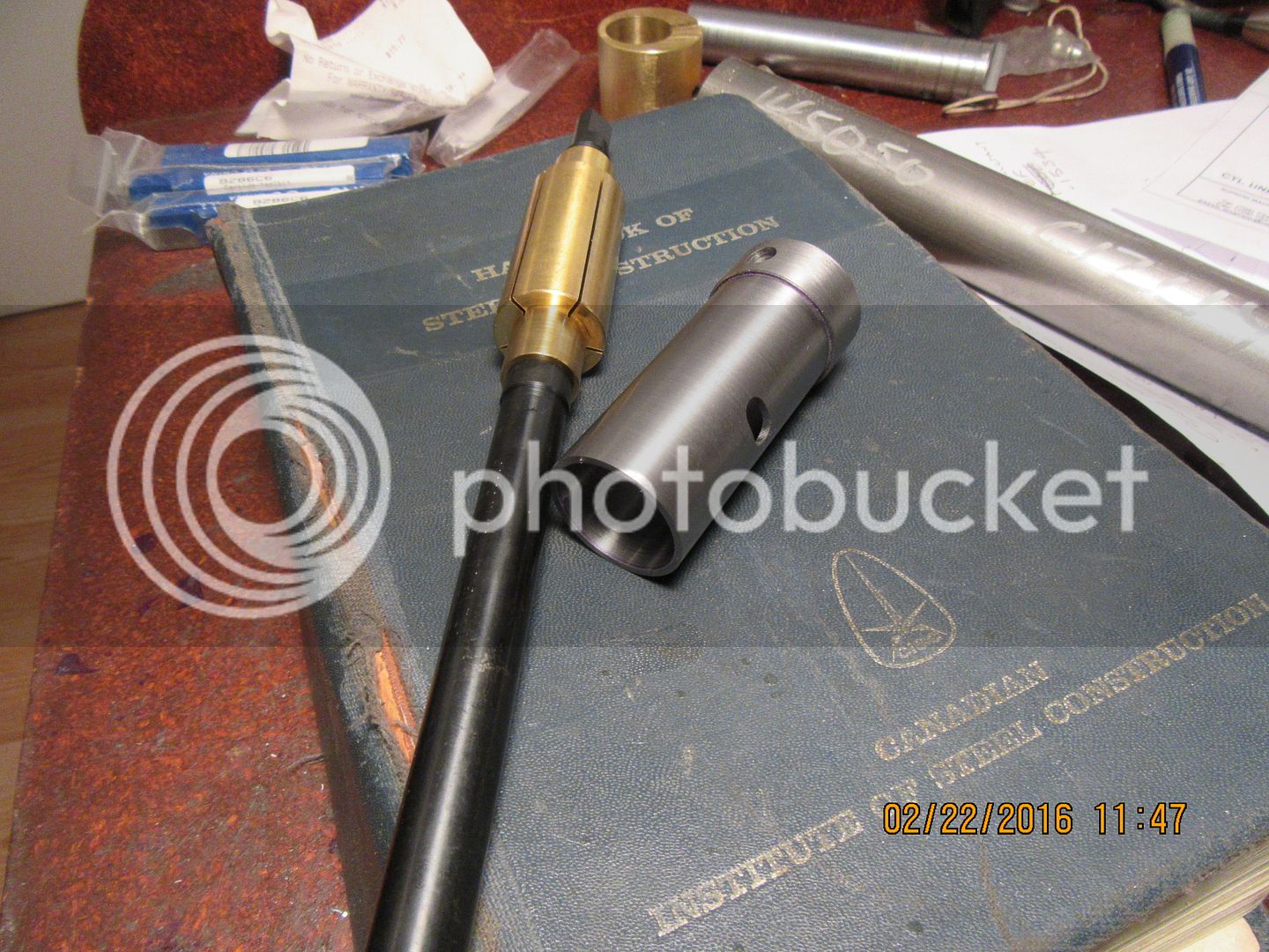
The liner has had the slots added for the ports, and the hole added for the sparkplug access, then parted off from it's parent stock, and finally faced to size. I had to go over to my tool supplier and pick up a couple of metric endmills, and my new internal lap was in. The fine diamond lapping compound is on back order, so I may have to make alternate arrangements there. There are a few minor burrs on the inside of the lap from milling the port slots. Should I do anything about that or just let the lap take care of it?--The inside of the bore come up really well from the boring operation.-Brian


- Joined
- Jun 24, 2010
- Messages
- 2,359
- Reaction score
- 931
Looks good. So this is a CI liner right? About how much material have you removed from boring diameter to get to that finish?
Just a word of caution on your brass piston lap. I made a similar one from aluminum. It can become a bit 'grabby' depending on the lapping compound grit + fit tightness + other variables. And by grabby I mean if it decides to stick just a bit, especially on a new incremental clamp setting startup or fresh lapping compound application, it can easily wrench your wrist & draw a nice line across your hand from that external bolt head. Gloves might actually be an added hazard. That's kind of the rub: an easily sliding fit is safer, but isn't really removing much material. You'll see what I mean.
A fine pitch bolt is much better than a coarse because of the tiny squeeze distances between stop & start. I think that's why the American lap tools are designed the way they are. The tool has radial relief holes & slits so its more even (radial) force & less clamping effort. The tool imparts its clamping force to thin, replaceable annular lapping sleeve, not the donut itself. Its easier to make replacement sleeves & keep the tool/ Also the sleeves can be preserved to respective grits.
btw - why do you think the lap decreased in ID once the slit was run through?
Keep up the documentary, interested to see how things come together.
Petertha No--that liner is made form 12L14 steel. The bore, as shown, hasn't had any lapping yet. that is just the bored finish.The piston is cast iron. I'm quite aware of the tendency to grab, as I lap all of my normal cylinder barrels for ringed engines using a piece of round aluminum .002" smaller in diameter than the cylinder bores. I chuck it up in the lathe, apply 600 grit lapping paste and run the cylinder back and forth over it by hand while it is turning at a low rpm. It is kind of a scary business, and you have to really be ready to let go in a hurry if it grabs. On a round cylinder letting go in a hurry is not usually a problem. The cylinder for my side valve engine had a large undercut feature on one side for lifter clearance, and it grabbed and tore a chunk of meat out of my hand. Luckily, it was only a small chunk of meat, about the size of a fox bite.--Sure woke me up in a hurry though!!! My plan was to use a fine thread bolt on my home-made brass lap, but as things usually go around here, I didn't have any fine thread bolts, so it got a 1/4"-20 unc thread. Why did the lap close up after the sawcut?--Probably internal stresses being released. I'm fairly sure that 1 1/2" diameter brass is rolled similar to cold rolled steel, and this imparts a denser outer surface than at the center. When I bored the hole in the lap off center and then cut through the side, the stresses in the brass from rolling released and closed up the cut.
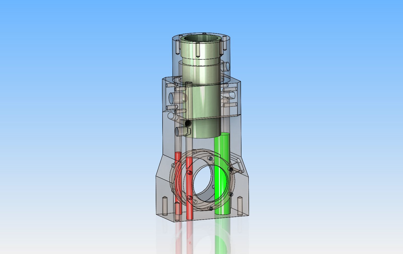
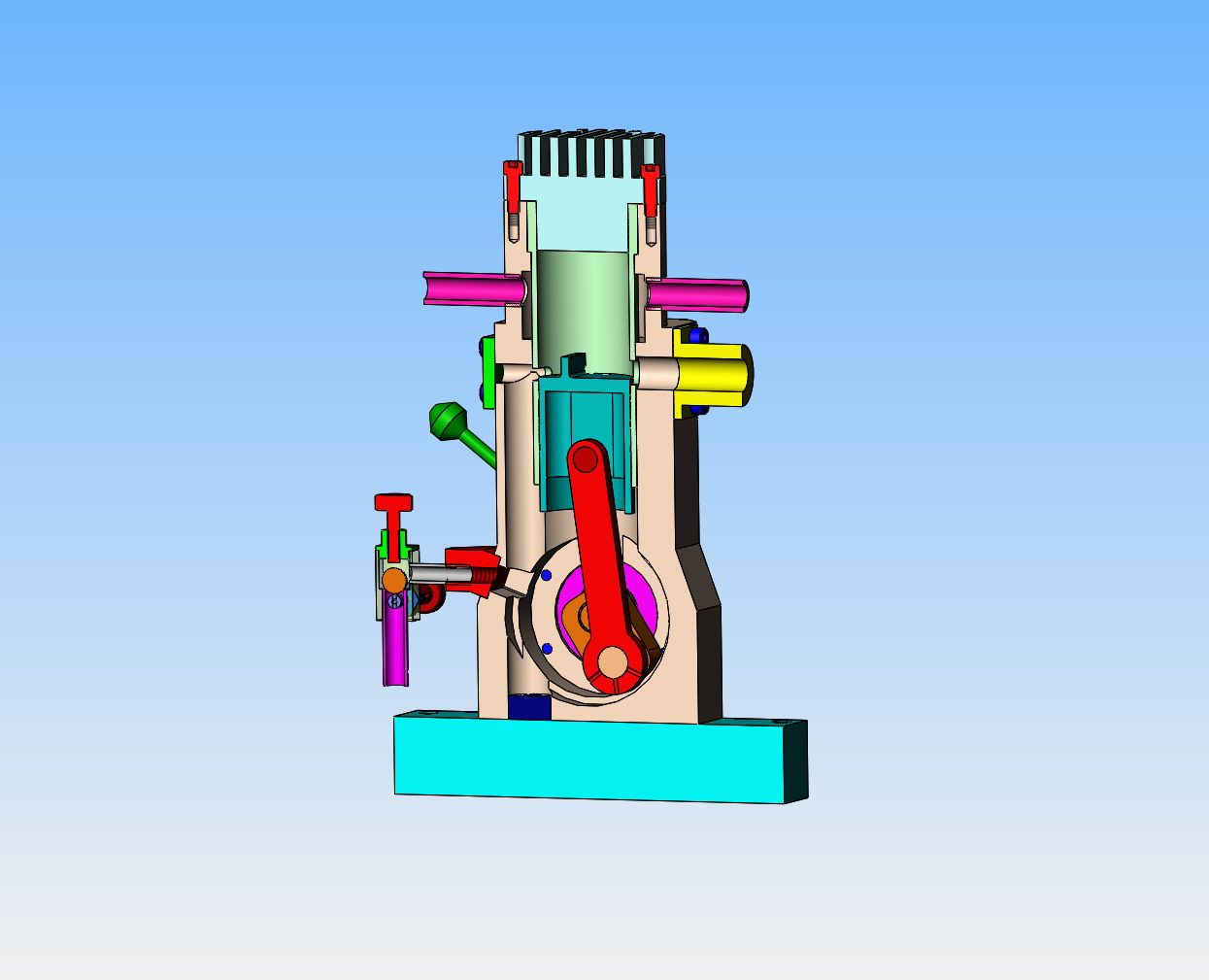
While I wait for my back ordered diamond lapping compound, it is time to move ahead with the next stage of the project. --the main body. Normally, on a casting, the water cooling and transfer port passages would be cast in place. Since I plan on machining the main body from a block of solid aluminum, I have to decide how to get the passages in there. The green represents a 7/16" four flute center cutting endmill, standard length, that can be plunged through the base, then through the internal cavity for the crankshaft, then back into the remaining solid material above the crankcase cavity. Any depth beyond the green endmill can be put in with a standard 7/16" drill, to finish the transfer passage up to the port. I can't use a drill to do the entire hole because the sloping sides of the crankcase cavity would make the drill want to wander off to the side. However, a drill will work fine in the flat bottom left by the endmill. The hole left in the base of the main body will have a plug loctited into place.BUT---, the red represents the cooling water passages up to the cavity around the cylinder liner. The water entrance and exit holes are through the sides of the main body, closer to the other end of the cylinder. These holes will be plugged and sealed directly above the crankcase cavity. and in the base of the main body.---and this presents a problem--because I can't get a 3/16:" endmill long enough to do what I want.
If I put the holes in before I bore the crankcase cavity, then no problem, I can just drill them and not worry about using an endmill. Only this screws up my planned sequence of operation. I have purchased an aluminum bar 10" long, and had planned to center it for perfect balance on my lathe faceplate to bore the crankcase cavity. Now I have to think on this for a while!!!
If I put the holes in before I bore the crankcase cavity, then no problem, I can just drill them and not worry about using an endmill. Only this screws up my planned sequence of operation. I have purchased an aluminum bar 10" long, and had planned to center it for perfect balance on my lathe faceplate to bore the crankcase cavity. Now I have to think on this for a while!!!
canadianhorsepower
Well-Known Member
- Joined
- Oct 22, 2011
- Messages
- 1,671
- Reaction score
- 324
and this presents a problem--because I can't get a 3/16:" endmill long enough to do what I want.
How long do you need it ??
I was in the same situation one day:wall:
I took the drill and sharpen it like an end mill
worked extremely whell
Luc--I was thinking of doing that. I need to be able to plunge at least 1 3/4". I can use an ordinary drill to go from the bottom into the crankcase cavity. then I could switch to the specially ground drill to just get a "flat" started in the material after I had passed thru the drill cavity, then switch back to a normal drill again. How would I grind the end of the drill? Just grind it flat on my grinder?
1) Cutting off the spare piece of bar so that you can drill the holes from the bottom of the crankcase does not mean you can't still use it as a balance weight.
2) Make a sacrificial crescent of alli to fit inside the bored-out crankcase so you can drill through solid all the way.
3) Drill a hole down the shank of the longest end mill you can get, and Loctite an
extension rod into it (but don't blame me if it comes unstuck).
2) Make a sacrificial crescent of alli to fit inside the bored-out crankcase so you can drill through solid all the way.
3) Drill a hole down the shank of the longest end mill you can get, and Loctite an
extension rod into it (but don't blame me if it comes unstuck).
canadianhorsepower
Well-Known Member
- Joined
- Oct 22, 2011
- Messages
- 1,671
- Reaction score
- 324
How would I grind the end of the drill? Just grind it flat on my grinder?
yep flat ( not 100% an end mill is not flat eather if is 100 flat it will walk all over the place )
on the side of the grinding wheel. when I did this I had promise a part
and I was able to mill in aluminium easy.
What I did : took a small piece of steel shorter then my drill
resurface the end with 2 degree taper the drill it with the drill I was going
to use. Then I put the cutting flute of the drill equal to the outside of my adapter and secure the tail of the drill with vice grip to keep the same length
all the time
and grind it to match my adapter
good luck
Last edited:
Charles--due to the shape of the internal crankcase cavity the sacrificial crescent idea won't work, but that would have been my first thought too. I can't really use your third idea either. The hole in the bottom of the crankcase where the 3/16" endmill gets admitted is right up tight against another surface, so there isn't room for the shank of a 3/16" endmill.

Great call, Rick!! By putting the water inlet on one side of the cooling water cavity and the water outlet directly opposite from it, I can totally avoid having to drill holes up through from the underside except for the transfer port, and it's not a problem for me.

canadianhorsepower
Well-Known Member
- Joined
- Oct 22, 2011
- Messages
- 1,671
- Reaction score
- 324
On a different forum.Brian
where is Rick's post can't see it
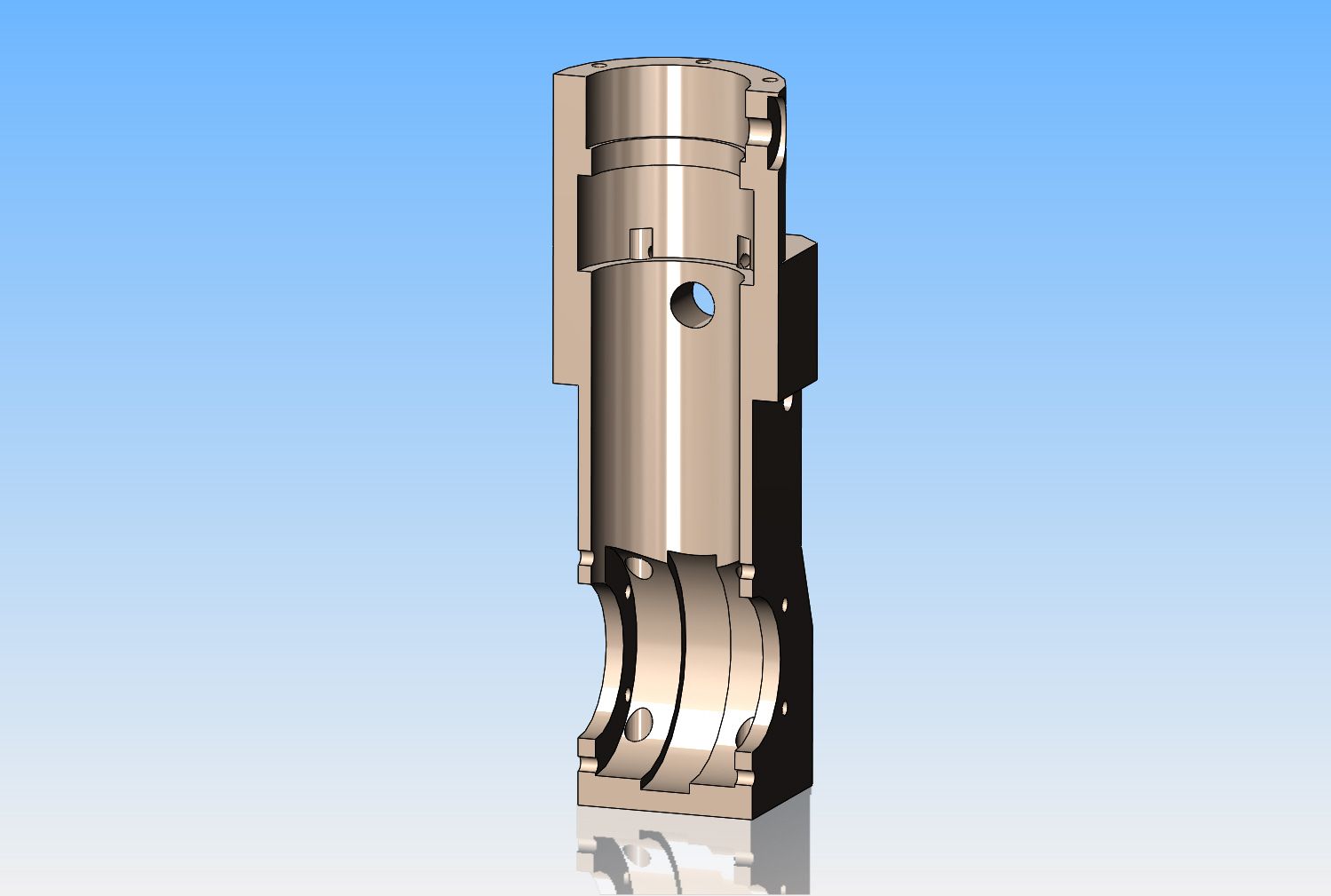
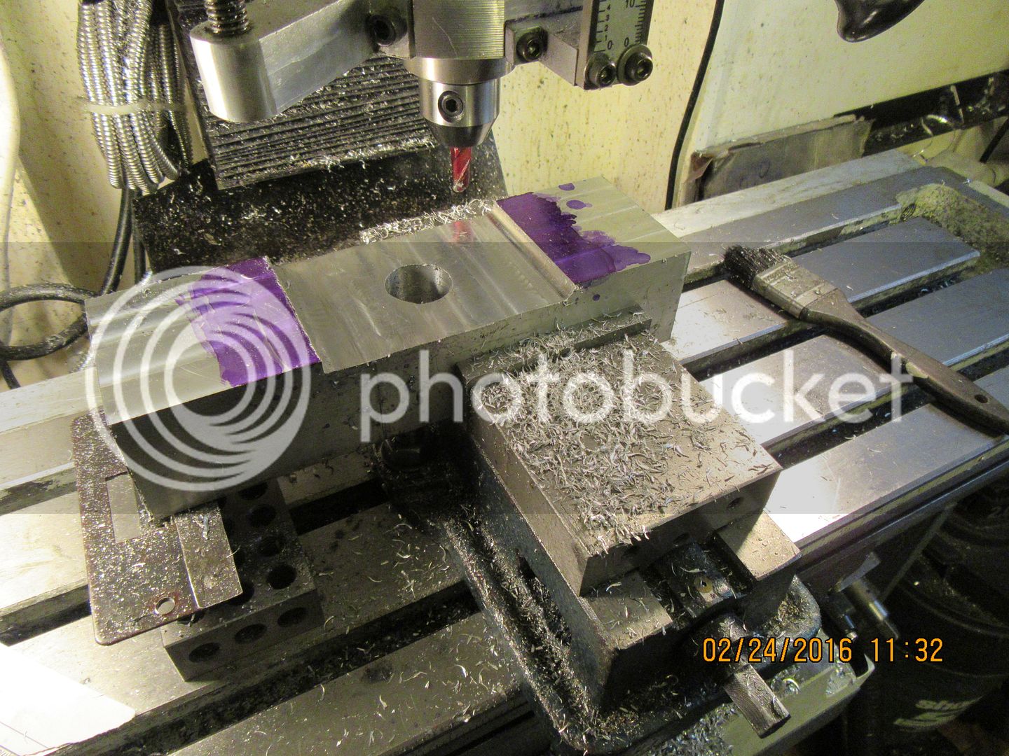
I went out yesterday and spent a whole $30 on a piece of aluminum bar 2 1/2" x 2" x 1 foot long. Since the finished part I am making is 5.009" overall length and 4.016" from the top of the cylinder down to the crankcase hole, I cut a piece of the bar 10 1/8" long so that I can mount it to my faceplate to turn the crankcase hole on my lathe. That length will allow the bar to be mounted on my faceplate with the hole on the center and an equal amount of bar on each side of the faceplate centerline for balance. I set it up in my mill, cleaned up the right hand end to be square, then measured down the appropriate distance of 4.016" and centered the quill on the bar, then drilled and reamed a 1" diameter centerhole. The finished bore of the centerhole is 1.063", so when I move my operation over to the lathe I can pick up on a short piece of 1" diameter shaft inserted into the hole to center it exactly on the faceplate and finish the bore. I had to take 0.153" of material off each side and then a farther 0.222" off near the center, so I used an endmill for that, and since most of the material on the other side of the crankcase hole is going to be cut off eventually, I left the material on that section so I will have two areas the same height when I mount it on the faceplate.---This will become clearer as I move along. Now I have to flip the part over in the milling vice and machine the far side the same way.

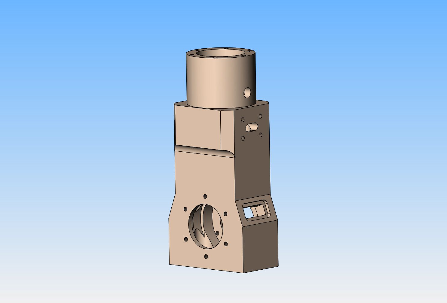
Bit by bit, the shape of the main body starts to emerge. Both of the "flat" sides are now machined, and I can't really do anymore now until I have mounted it on my faceplate and turned the center cavity for the crankshaft, otherwise it will throw everything out of balance. The plan for right now is to mount it to the facelate, bore the center cavity, then probably mount it between centers to turn the round section at the top of the cylinder next.


modelman1838
Well-Known Member
- Joined
- Oct 1, 2011
- Messages
- 51
- Reaction score
- 6
I have built a number of hot air engines with lapped cylinders and pistons in mild steel and cast iron, I make the cylinder lap out of brass because it is usually a silver soldered assembly, but always use aluminium for the piston lap and it works just fine, best of luck.
Hugh
Hugh
then probably mount it between centers to turn the round section at the top of the cylinder next.
If you did the bottom face and bolt holes next, you could mount it on the faceplate by the base (perhaps on an intermediate plate) and do all the barrel turning at one setting? Alternatively, a chunky angle-plate, if you have one of the type that is machined on the inside faces.
Last edited:
Charles---there is wisdom in what you say. I haven't totally got my head around what I will do next. The main body is currently up on the faceplate getting the crankcase bore completed. I have finished the 1.063" thru bore, but haven't yet put the larger stepped bores in yet. I have sorted out the boring bar and tool I will use for the job tomorrow. My big concern is that I have the cylinder bore perfectly square to the crankshaft. On a piston with rings, there is a very small bit of "forgiveness" because the piston has about .001" radial clearance in the cylinder. However, on a ringless piston like this will be, I'm sure that any "out of square" will throw some serious binding into the rotation of the crankshaft. I may do exactly what you have suggested---will think about it more tomorrow. There is a certain "sequence" to the machining of this main body, that if not fully thought out, can leave me with nothing to hold onto to finish it.---Brian
So---An afternoons entertainment, and the chatter marks come free!! What?---You can't see the chattermarks?--Trust me, they're there. I could say something about the length and the strength of my tool, but this is a family forum, right!! It was a "work with what you got" kind of thing, and I really didn't want to get anything on the carriage close to all those things whirling around on the faceplate. Everything seems to have went well, but it was both noisy and tedious with such a long and limber boring tool. Oh well, when it's all buttoned up, nobody will know about the chattermarks but me.---Right!!!----


As I get deeper into this thing, it becomes apparent pretty quickly why people cast them!! The upper cylindrical portion of the cylinder is turned to size. I still have a lot of material to cut away. However, it's February, it's snowing outside, and right now I've got nothing better to do. I never thought I would say this, but "Thank God for power feed!!!"


Similar threads
- Replies
- 14
- Views
- 5K