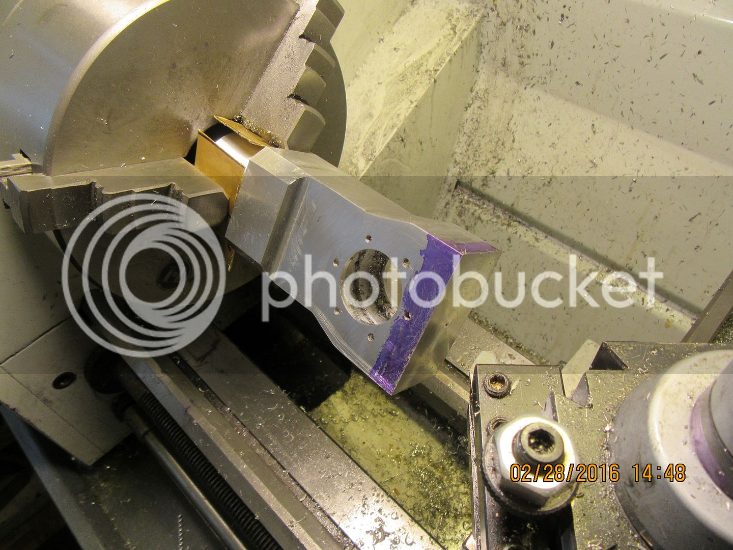
Old School Barstock 2 Stroke

Home Model Engine Machinist Forum

Help Support Home Model Engine Machinist Forum:

This site may earn a commission from merchant affiliate links, including eBay, Amazon, and others.
Regardless of my best intentions, the base of the main body did not turn out to be parallel with the bore for the crankcase. This gave me some pause, as I couldn't figure out quite what to do to correct it. I thought about it for a few days, and then come up with my standard solution---"When in doubt, make a fixture!!!" So---I turned a piece of steel round bar to be an exact fit into the crankcase bore.Then made up a short piece of steel flat bar with a couple of bolt holes to pick up two of the threaded crankcase holes. I bolted the flatbar to one side of the main body, slid the round shaft thru the hole in the crankcase until it was tight against the steel bar, covered all of my aluminum part with 3 layers of masking tape to avoid weld spatter, then walked it out to the main garage and mig welded the flatbar to the roundbar. Now I had something I could hold in the chuck on my rotary table. this automatically established the centerhole in the crankcase as being truly vertical. Then I indicated the base and played with the rotary table until I had zero runout in the Y axis. Then I machined the base flat with the side of a 1" endmill, taking very light cuts. I had painted the base where I was cutting it with layout dye, and it was out of "true" by a surprising amount. This was okay, because I had delibarately left the main body about .050" longer than it's finished length just in case I had to undertake a further machining operation to square it up.

 
I have no clearly defined idea of what on earth I'm doing here, but as usual it hasn't stopped me. I am following posts by Jason and Ramon, hoping I get it mostly right. The lap has been smeared with 320 grit carborundum paste, and "enlarged" by turning the screw in the end of the lap until I felt it begin to "drag" as I held the cylinder liner in my hand and worked it back and forth on the lap, with the lathe running at about 40 rpm. I repeated this "enlarging" of the lap about 3 times as material wore away from the exterior of the lap and the interior of the cylinder liner. At one point, it begin to grab a bit and squeal, so I squirted a bit of cutting oil on it. This loosened things up a bit. I didn't want to turn the liner to an i.d. larger than the piston I already have made, so have taken the lap out and washed it with Varsol and an old paint brush, then blown it clean as I can get it with 100 psi of air pressure. I have also thoroughly washed the liner. My next trick will be to repeat this operation with 600 grit carborundum paste, then finally with my diamond paste which arrived today. The liner has taken on a uniformly "matt" finish on the inside diameter at this stage of the operation.
 
My home made external lap seems to work fairly well. I have started with 320 grit carborundum paste, and by running the lathe at about 40 rpm and working the lap back and forth while holding it in my hand (ready to instantly let go if it grabs) the piston has taken on a consistent dull finish. As near as I am able to measure, I have to take about .002" off the diameter of the piston before it fits into the cylinder.--Herein lies the rub---I don't know how much I am taking off as I lap the outer diameter of the piston, so I have to frequently stop and "try for fit" because I don't want to make the piston too small.
 
Things are not going as smoothly as I had hoped---My hands are sore from holding the external lap to lap the outer diameter of the piston. I have lapped it until the surface has a smooth matt finish and I can't measure any difference in diameter from one end of the piston to the other. However---it will only go about 1/3 the length of the piston into the sleeve without binding. I conclude from this, that my pretty brass barrel lap is "bell mouthing" the bore of the sleeve. This doesn't surprise me, as I see now that when you expand this lap, it gets larger in the center, somewhat like a snake which has just swallowed a frog. All is not lost. This cylinder as designed, is 24 mm ( 0.945") bore. My reasoning was that I could buy a 15/16" (0.9375") barrel lap and expand it to the required 0.945". Having no experience with barrel laps, I didn't know it would expand only at the middle, but not at the ends. Oh, stupid me!!! So--tomorrow, I will turn a piece of aluminum to the desired diameter and use it to finish lapping the bore and hopefully get rid of any bell mouth. An actual measurement of the piston informs me that it is currently 0.943" diameter, and to the best of my knowledge is quite parallel from one end to the other. It is not really important that I hit the exact 24 mm (0.945")----It is only important that the piston be a very good fit into the sleeve.
 
I'm not quite following what happened. (I have the exact same lap & size btw). Yes the lap expands in the center so has an enlargement there. But that enlargement must pass through the liner from end to end. If the ID is larger, you hear no cutting action. If its smaller the lapping compound goes to work. I'm no expert. I've done about 3 now testing different liner materials, but at least this aspect is consistent. Once the bore is uniform matt finish on any given grit & it feels the same lapping resistance, they bore check very, very similar from crown to mid to bottom. Something must be 'different' here, but I cant quite tell what.

http://www.homemodelenginemachinist.com/showthread.php?t=25163
 
Having used laps for bores, I want to say that one must operate the lap in a manner
that causes it to cut the area of concern. I hope I'm not preaching to the choir but
I haven't read any thing in these lapping posts about this so I'm going to just say it.
A lap won't automatically make a parallel bore or piston. One must lap and measure,
lap and measure, over and over. Work the tight spots with the lap until the desired size
and straightness is achieved.
If this is done carefully the laps won't ever get way out of shape but they still
will wear a bit. The worst is the lap for the bore as Brian has found. The best
is the OD lap as it's usually short in comparison to the length of the part it's
working, so one has to just use it to reduce the big spots on the rod/piston which is
easy to do as they can be felt while lapping.
The lap for the bore has to be manipulated using actual measurement as
a guide to straightness. At least until the last tenth or two which should be
done with a newly turned and parallel lap.
Sorry if I'm providing redundant information, just want to see you all succeed.

Pete
 
The fact that the lap bulges in the middle should help you to avoid bell-mouthing the bore. You should be able to feel the tight spots in the bore as you pass it over the hump, and dwell on those parts until you feel even drag all the way along. I think if it is making your hand sore you may have the lap too tight.
 
I have finished lapping the cylinder. I used 300 grit carborundum to start with, then 600 carborundum, then diamond. The liner has gone from grey matt finish to a lighter silver color. Same with the piston. As I said, the piston is just beginning to enter the bottom of the cylinder. Perhaps I will try as Jason says, and try lapping the piston into the liner with lots of oil.
 
I want to make a statement here, and I want you all to pay attention!! LAPPING PISTONS INTO LINERS ISN'T FOR SISSIES!!!! I didn't make any more laps. I followed Jason's advice, and since the piston would just start into the bottom end of the liner and go no farther, I lapped the piston into the liner. This was a slow and somewhat tedious procedure, and about every 25 seconds I had to shut off the lathe, remove the piston which was now firmly stuck in the liner, and take both piston and liner out to my shop press and push the piston free with a short section of broom handle. I used a lot of oil, and a little bit of diamond grit during this process. Gradually, the piston would go farther and farther into the liner without binding, until it had entered completely, and then on up to about 0.100" past it's maximum travel into the liner under running conditions. How tight is a "good fit"---well, I'm not sure. With all the oil wiped off, the piston will not fall thru the liner under gravity. However, with only moderately light finger pressure, I can push the piston thru with no problem. When the piston is inserted into the liner, it passes the "Blow your guts out" test.---that is to say, with my fingers closing the ports and one end of the liner in my mouth, I can't blow any air past the piston. My thoughts are, that any remaining interference between piston and liner will sort itself out once the engine is running. I hope that is right.
 
..done carefully the laps won't ever get way out of shape but they still will wear a bit..
Pete
My experience was they can wear 'quite a bit'. But I'm sure that's a function of lapping grit, liner material, lapping alloy, removal amount... etc. & everyone's mileage may vary. For example on my cast iron liner (harder material) I was progressively pinching in the screw, lapping away. At some point I decided to change grits...which most experts say is a no-no, probably correct, but moss was starting to grow on my head with impatience. I relaxed the screw, cleaned the brass, re-assembled & just out of curiosity measured the barrel diameter on ends vs. now relaxed/contracted middle bulge area. Sorry don't have numbers in front of me right now, but lets just say 'a lot' relative to thousanths of bore diameter. The laps job is to hold grit, but some barrel consumption seems inevitable. I could see a greasy yellow tinge in the slurry.

Personally I've concluded the bore has to be as close to bang on within a couple thou of target diameter prior to lapping & of course as straight as possible to begin with. Or, you make up for it in lapping time & related consumables. But I'm also no expert, just an opinion thus far.

What the very first couple lapping passes showed me as the surface started to matt up was, despite my best efforts on the prior boring side, spring passes, locked carriage, changing travers & rpm speeds etc. there is a bit of technique to getting the bore geometry right beforehand. Lapping really hilites that. What could be called bell-mouthing might be an artifact of boring. I'm not saying this is the case in Brian's liner because he looks to be at matt finish stage.

I also did a test of the auto-parts 3-stone brake (deglazing?) hones. It didn't take me long to throw in the towel there. I had a very consistent straight bore to begin with & it turned bell-mouthed in no time. There's probably a technique to that too that I could improve on, but it wasn't for me.
 
I guess my next trick will be to suss out a way to hold the main body and baseplate to the faceplate, to bore the hole for the liner.The baseplate is going to have to be clamped to the faceplate, but with enough adjustment that I will be able to move it around a bit to indicate "center" based on the outside diameter of the main body at the round end.
 
I guess my next trick will be to suss out a way to hold the main body and baseplate to the faceplate, to bore the hole for the liner.The baseplate is going to have to be clamped to the faceplate, but with enough adjustment that I will be able to move it around a bit to indicate "center" based on the outside diameter of the main body at the round end.

Hi Brian
I simply not getting it:hDe::hDe:
why not using your mill and boring head
that's what it's made for

the more mass, the longer you are from your face plate,
the more tricky the set up is.

the more doors you are opening to Murphy's law :fan:

good luck
 
And now you know how I spent my Saturday!! the instructions say to glue the liner in place with #574 Loctite. This is a loctite that is not stocked in Canada. The minimum amount I can by if I order it in from USA is a 1.7 fluid ounce bottle for $50---Does anyone know of an alternative that I can buy in Canada, that has the same properties?


Hi Brian
I simply not getting it:hDe::hDe:
why not using your mill and boring head
that's what it's made for

the more mass, the longer you are from your face plate,
the more tricky the set up is.

the more doors you are opening to Murphy's law :fan:

good luck
Luc--Can't turn an internal water jacket recess with the mill.
 
Luc--Can't turn an internal water jacket recess with the mill.

and why not :hDe:

I'm totaly confuse,
the rotation is OK the length is good enough
the travel is good enough :confused::confused:

please explain I have an 877 Busy bee and I can do it
 
Luc---There is a dirty little secret to boring something in the mill. If its a "completely thru" bore, there is no problem. if it is a blind hole, then there is no problem, assuming you can mount it with the open side up. The problem comes when you have something like a hole thru the center of this block where the crankshaft ultimately goes--The hole is larger in diameter in the center of the block than it is on the outsides of the block. In a lathe, that is no problem, because you can wind out the cross slide while the piece is turning, and the boring tool will cut it's way out to the larger diameter . In a mill, unless you have a very specialized boring head, (which I don't) you have to shut the mill off to advance the boring tool. Do you see where I am going with this? You have to advance the tool into a stationary part. Then you have to restart the mill with the tool already jammed into the material.--Not good!!! And every time you want to advance the boring head, you have to stop the mill to do so. It gets really nasty, really quick!!!
 
Last night I went to bed, all pleased with myself, and the fact that I had successfully lapped a piston into a liner for the very first time. And then, as I lay thinking about it, a thought struck me!!!--Due to the construction of this engine, the piston with con rod attached has to be lowered down thru the top of the liner, and then the "driver" side of the crankshaft has to be inserted from one side of the crankcase bore so that the rod journal engages the big end of the rod.---AND--I had lapped the piston into the cylinder liner from the bottom until it reached a spot about 0.100" beyond where it would travel in the liner under running conditions.--However, it still wouldn't go all the way thru the liner---which meant I would not be unable to insert the piston/con-rod assembly thru the top of the liner when I went to assemble the engine.---So---This morning I got up, put my "lapper hat" back on, and continued lapping until the piston fits completely thru the liner.
 

Latest posts

Back
Top