


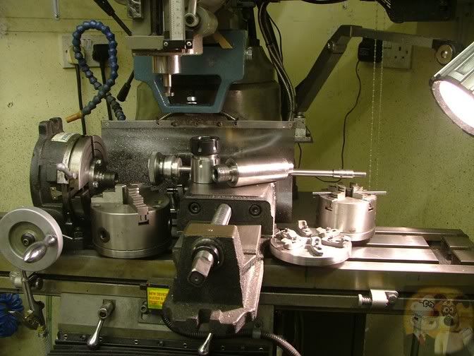
Here is a post about my interchangeable tooling upgrade, where I can swap between my lathe and the RT on my mill at will without having to move the piece part from the chuck. I have a nose converter for my lathe, which can change it from D1-4 to Myford thread, this is about the other half.
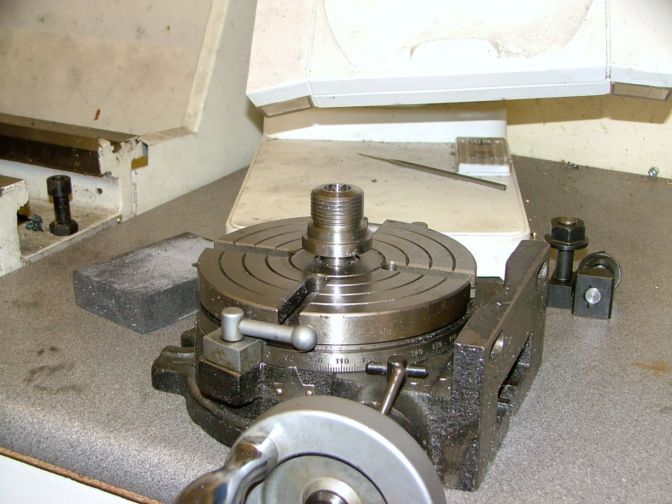
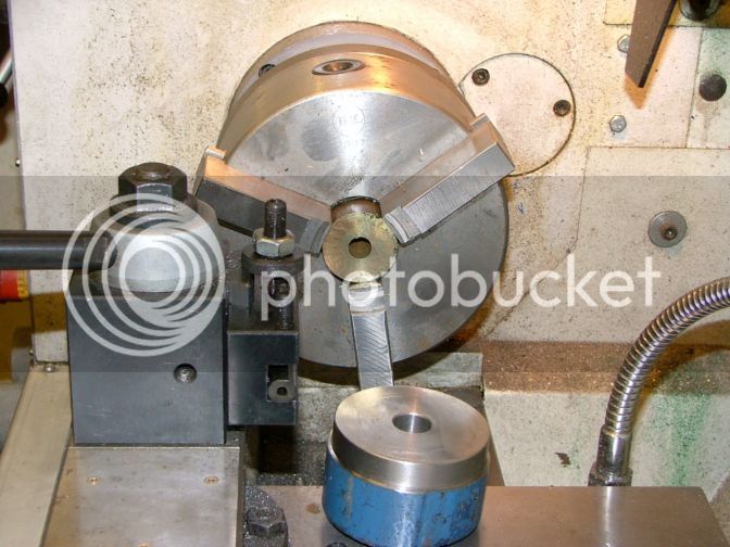
So this is what I am replacing this time, the 2MT adapter with a Myford nose on it.
These have kept me going for a while, but I am just not happy with some of the surface finishes I am getting due to lack of rigidity. I just don't like cleaning up machining marks.
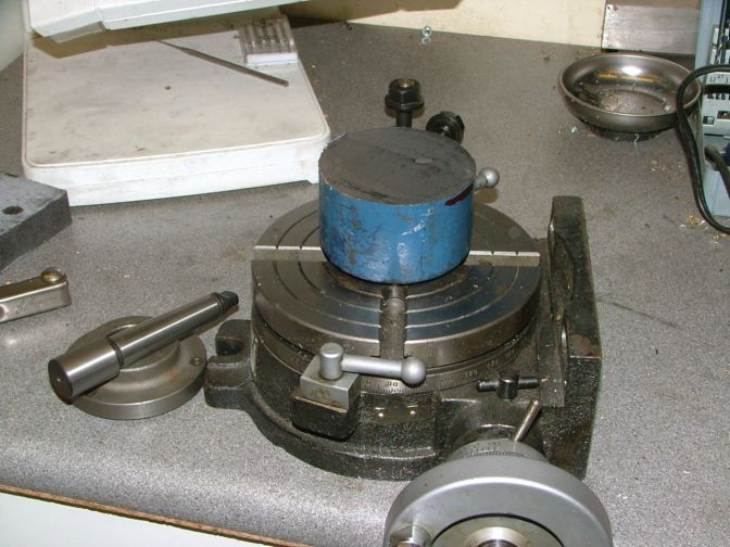
This big blue lump is what I am going to make it out of. I was given a long length of this stuff, I have a feeling in the back of my mind that it is cast iron, but I am not sure. I think it is an end of day pour and everything left over got thrown in the pot. You can just see a light patch on the cut face. This is a counterbalance weight off a garage door and they just stuck a length of bent rod in the casting box to make a hanging loop, that is a bit of the steel rod.
But this doesn't have to withstand massive forces, so it will do.
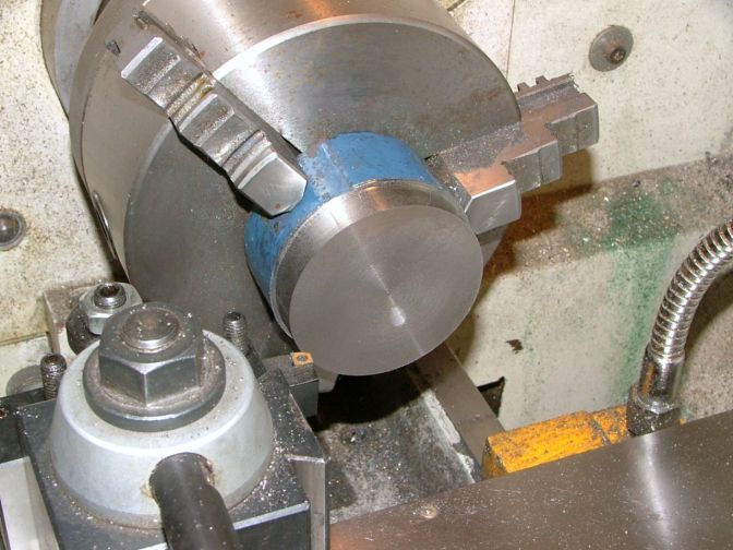
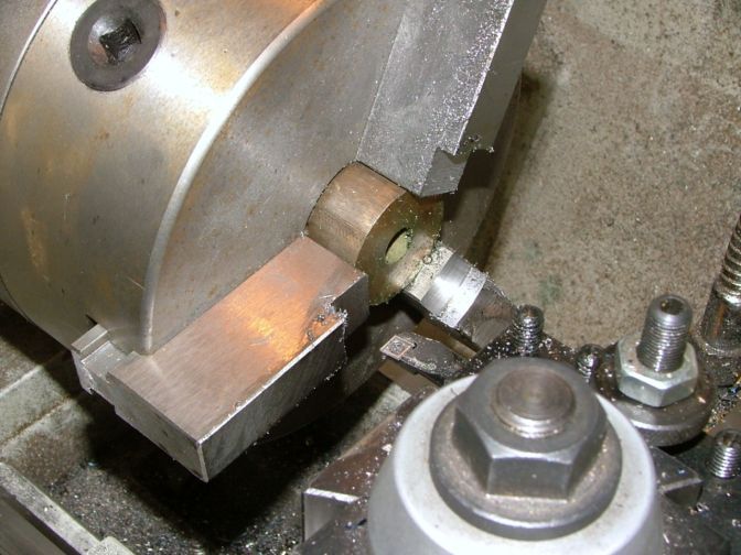
The lump was mounted into the 3 jaw and I attacked the hard outer skin with a pair of roughing tools. The skin must have been around 1/16th of an inch thick, but once the tool got under it, it came away fairly easy. I am preparing the metal here for all the following machining operations. I have created a main datum bottom face and a perfectly square side to it.
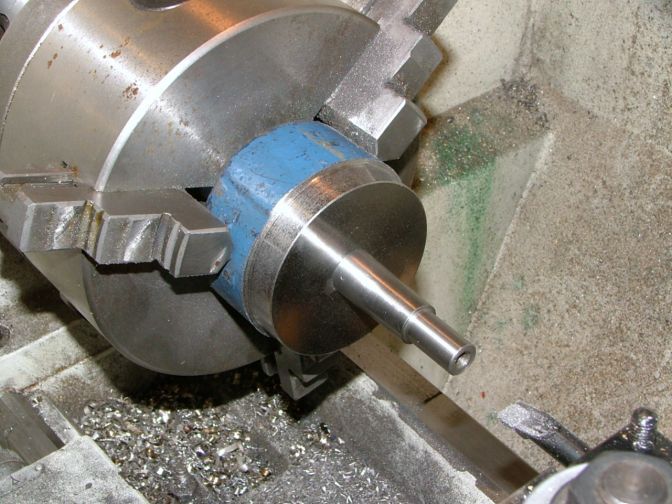
The centre hole was then drilled and fine bored to accept a close tolerance fit of the MT locating spigot. The spigot had previously had a non tapered area machined on it. It is that close fitting machined end and this bored hole that will align the adapter perfectly central on the RT. So that is all the datums produced to close standards. Now I had to make sure that everything else was square to these datums.
Out came the soft jaw chuck.
I love working with soft jaws, because if they are used correctly, your accuracy and concentricity of parts takes a massive leap forwards, and for stuff larger than normal collet work, knocks four jaw working into the shadows, because it is so easy to do.
With the jaws tightened down onto a bit of stock bar, the jaws are gently bored until you can just fit your turned part into the made recess.
Once that stage is reached, the barstock is removed and every burr on the machined area is dressed down and inside the jaws are cleaned up spotless.
The datum faces can now be clamped up in the soft jaws, and gently bedded into the recess.
You can now work with confidence in the knowledge that anything you machine up outside the jaws will be perfectly square and concentric to the datum areas.
The part will not be removed from the chuck until every machining exercise is completed, except for the mounting holes.
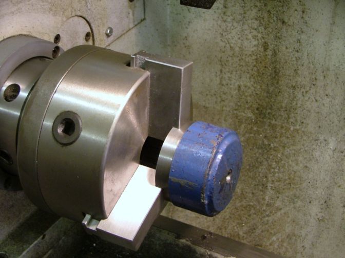
The roughing tools were brought into action again, and they soon got rid of the tough outer skin and a lot of the bulk on the part.
Then everything was turned up in preparation for single point cutting the thread.
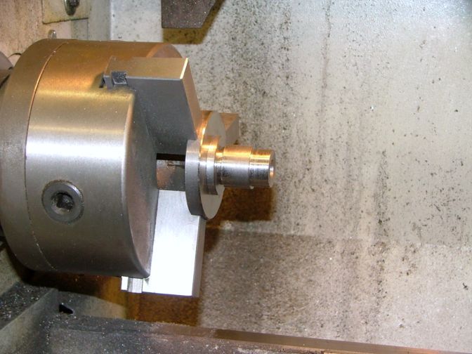
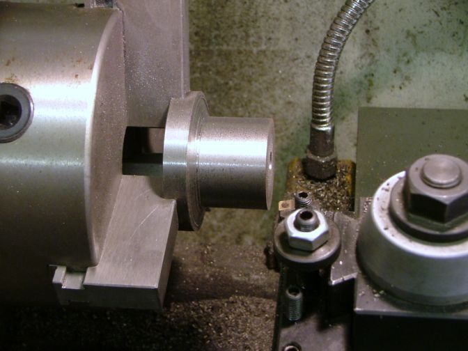
The threading and other size getting machining was carried out, then I bored down to meet the previously bored hole. but this time it was about 10 thou larger in diameter. I had drilled and tapped the end of the locating spigot, and by feeding a bolt down this hole, I can remove the spigot if I need to hold a bit of long rod in the chuck, this will allow me to hold a rod over 6" long down in the RT.
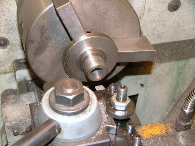
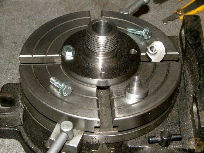
This shot shows the locating spigot in position and the new backplate with threaded nose.
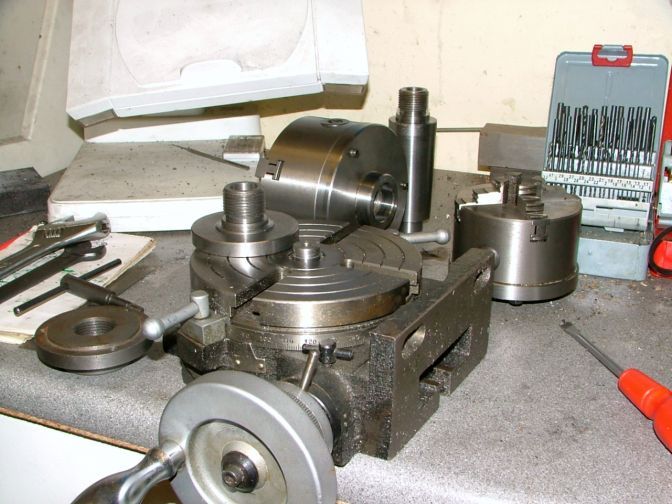
This is how it will fit together.
The backplate just needs four holes drilling and I need to make up the t-nuts and bolts. I got the holes in the adapter plate drilled by bodging together a holder and drilling them using the RT.
As you can see, the t-nuts are a rather weird shape, that is because with the disc being so small, I was working at the very inner limits of the slots. They hold just fine.
I marked up the adapter with a '0', this hole, if ever the plate is removed, will be put back in line with the '0' on the scale around the RT.
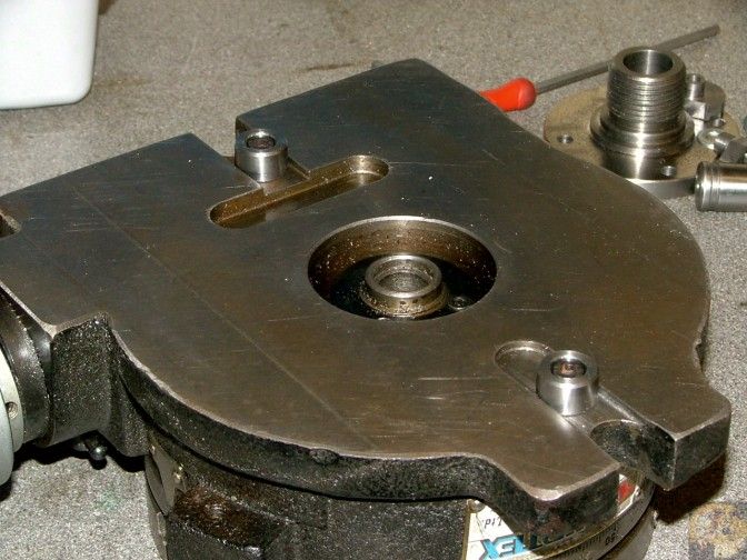
This is the side you very rarely see. But I noticed that the slots and holes were there if ever I wanted to put locating blocks onto the bottom. So why not?
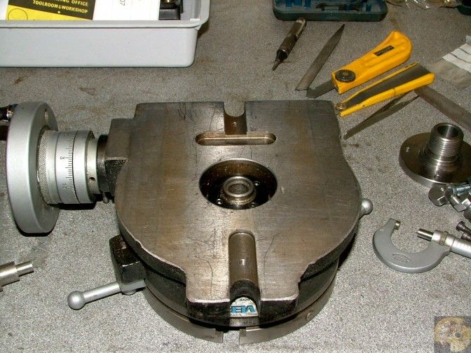
So I got my aligning blocks off the mill, and they fitted perfectly in the slots. So they are the same as the mill, 0.625" wide.
This is going to be real easy for a change. So I grabbed a bit of steel scrap and set to work.
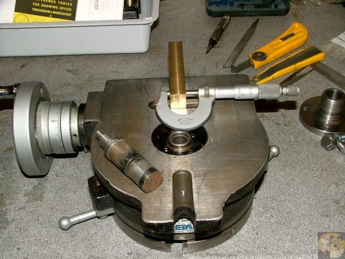
First off, the bar was turned down to 0.624", this will allow for a minor irregularity in the mill table, if there is one.
It was then drilled thru with a 5mm drill, and a recess put in the end for a cap screw head. Two were made, both 1/2" long.
They were screwed into position in the slots.
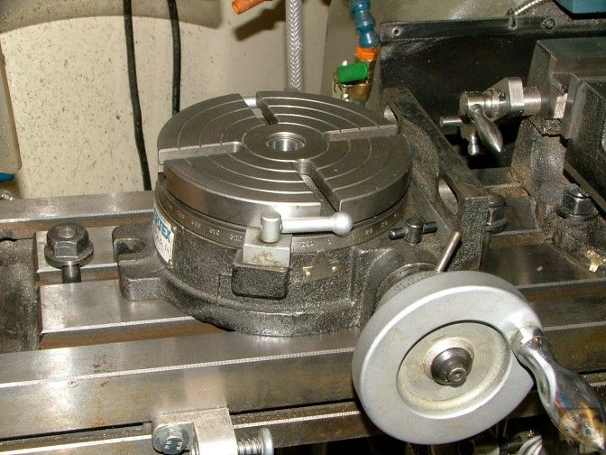
It fitted perfectly onto the mill table.
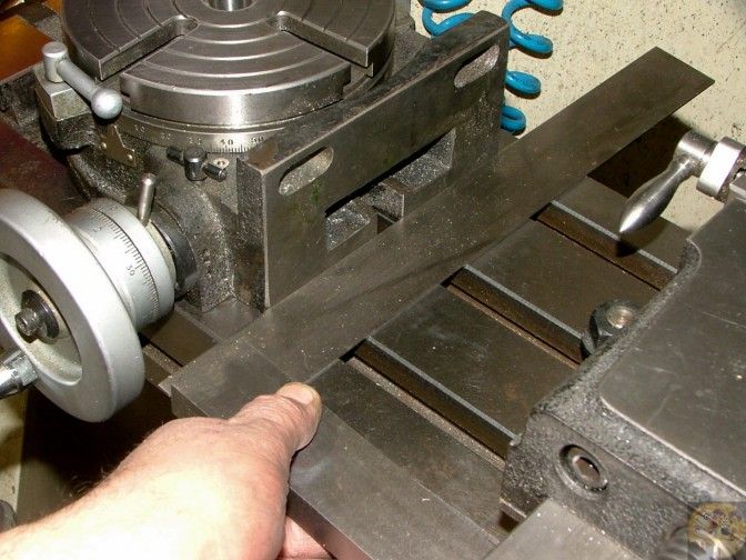
And a check with a square showed they had done their job.
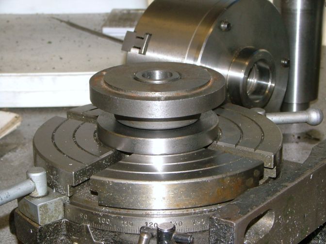
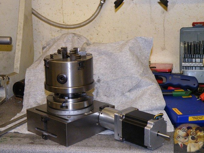
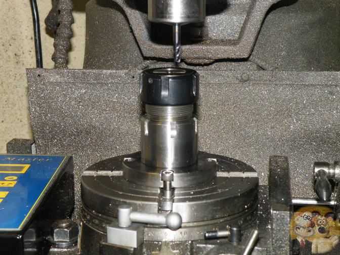
The RT was bolted down into it's final resting place, and I got the RT perfectly aligned with the quill.
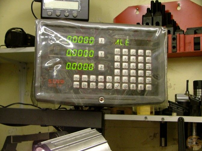
Reset the DRO to zero, just to make sure nothing had moved when I do the next check.
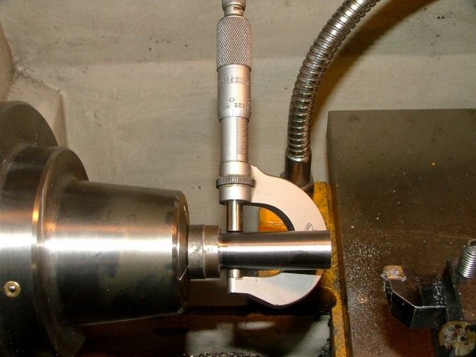
The aligning spigot was dropped into the 2MT centre of the RT, and the adapter was bolted down into position.
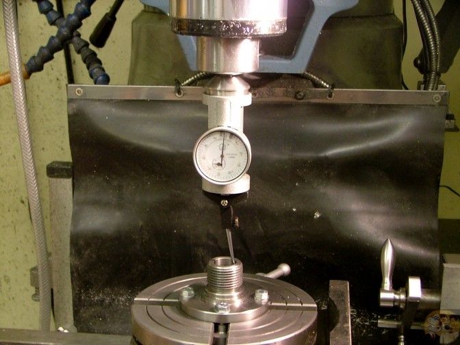
Checking to make sure the table hadn't moved at all, I checked the runout of the centre bore of the adapter.
Just under 1 thou runout, in fact as close as I can see, 0.0008".
That will do me just fine.
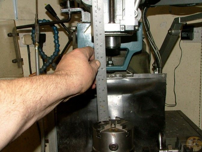
As an added bonus, I have gained about an inch in throat depth over the previous fitting.
So at this time, I class this as a good result.
John
So this is what I am replacing this time, the 2MT adapter with a Myford nose on it.
These have kept me going for a while, but I am just not happy with some of the surface finishes I am getting due to lack of rigidity. I just don't like cleaning up machining marks.
This big blue lump is what I am going to make it out of. I was given a long length of this stuff, I have a feeling in the back of my mind that it is cast iron, but I am not sure. I think it is an end of day pour and everything left over got thrown in the pot. You can just see a light patch on the cut face. This is a counterbalance weight off a garage door and they just stuck a length of bent rod in the casting box to make a hanging loop, that is a bit of the steel rod.
But this doesn't have to withstand massive forces, so it will do.
The lump was mounted into the 3 jaw and I attacked the hard outer skin with a pair of roughing tools. The skin must have been around 1/16th of an inch thick, but once the tool got under it, it came away fairly easy. I am preparing the metal here for all the following machining operations. I have created a main datum bottom face and a perfectly square side to it.
The centre hole was then drilled and fine bored to accept a close tolerance fit of the MT locating spigot. The spigot had previously had a non tapered area machined on it. It is that close fitting machined end and this bored hole that will align the adapter perfectly central on the RT. So that is all the datums produced to close standards. Now I had to make sure that everything else was square to these datums.
Out came the soft jaw chuck.
I love working with soft jaws, because if they are used correctly, your accuracy and concentricity of parts takes a massive leap forwards, and for stuff larger than normal collet work, knocks four jaw working into the shadows, because it is so easy to do.
With the jaws tightened down onto a bit of stock bar, the jaws are gently bored until you can just fit your turned part into the made recess.
Once that stage is reached, the barstock is removed and every burr on the machined area is dressed down and inside the jaws are cleaned up spotless.
The datum faces can now be clamped up in the soft jaws, and gently bedded into the recess.
You can now work with confidence in the knowledge that anything you machine up outside the jaws will be perfectly square and concentric to the datum areas.
The part will not be removed from the chuck until every machining exercise is completed, except for the mounting holes.
The roughing tools were brought into action again, and they soon got rid of the tough outer skin and a lot of the bulk on the part.
Then everything was turned up in preparation for single point cutting the thread.
The threading and other size getting machining was carried out, then I bored down to meet the previously bored hole. but this time it was about 10 thou larger in diameter. I had drilled and tapped the end of the locating spigot, and by feeding a bolt down this hole, I can remove the spigot if I need to hold a bit of long rod in the chuck, this will allow me to hold a rod over 6" long down in the RT.
This shot shows the locating spigot in position and the new backplate with threaded nose.
This is how it will fit together.
The backplate just needs four holes drilling and I need to make up the t-nuts and bolts. I got the holes in the adapter plate drilled by bodging together a holder and drilling them using the RT.
As you can see, the t-nuts are a rather weird shape, that is because with the disc being so small, I was working at the very inner limits of the slots. They hold just fine.
I marked up the adapter with a '0', this hole, if ever the plate is removed, will be put back in line with the '0' on the scale around the RT.
This is the side you very rarely see. But I noticed that the slots and holes were there if ever I wanted to put locating blocks onto the bottom. So why not?
So I got my aligning blocks off the mill, and they fitted perfectly in the slots. So they are the same as the mill, 0.625" wide.
This is going to be real easy for a change. So I grabbed a bit of steel scrap and set to work.
First off, the bar was turned down to 0.624", this will allow for a minor irregularity in the mill table, if there is one.
It was then drilled thru with a 5mm drill, and a recess put in the end for a cap screw head. Two were made, both 1/2" long.
They were screwed into position in the slots.
It fitted perfectly onto the mill table.
And a check with a square showed they had done their job.
The RT was bolted down into it's final resting place, and I got the RT perfectly aligned with the quill.
Reset the DRO to zero, just to make sure nothing had moved when I do the next check.
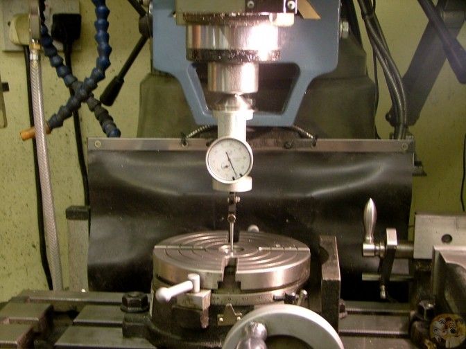
The aligning spigot was dropped into the 2MT centre of the RT, and the adapter was bolted down into position.
Checking to make sure the table hadn't moved at all, I checked the runout of the centre bore of the adapter.
Just under 1 thou runout, in fact as close as I can see, 0.0008".
That will do me just fine.
As an added bonus, I have gained about an inch in throat depth over the previous fitting.
So at this time, I class this as a good result.
John
") ...if you have any RT clamp-down do-dads or techniques you have come to like, I'd be interested to learn.
...if you have any RT clamp-down do-dads or techniques you have come to like, I'd be interested to learn.