- Joined
- Jul 16, 2007
- Messages
- 2,987
- Reaction score
- 1,055
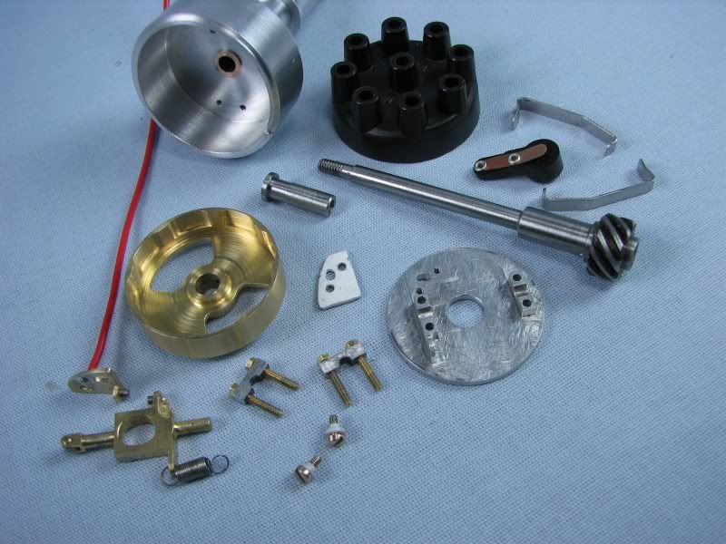
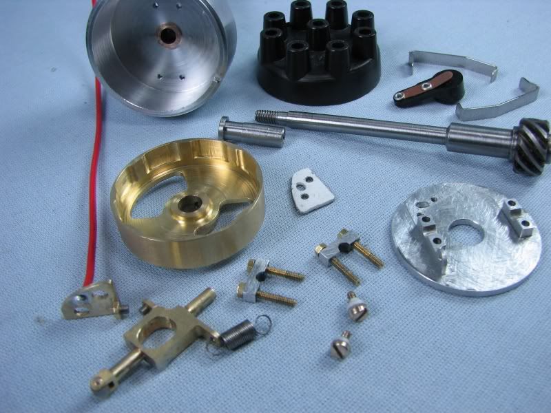
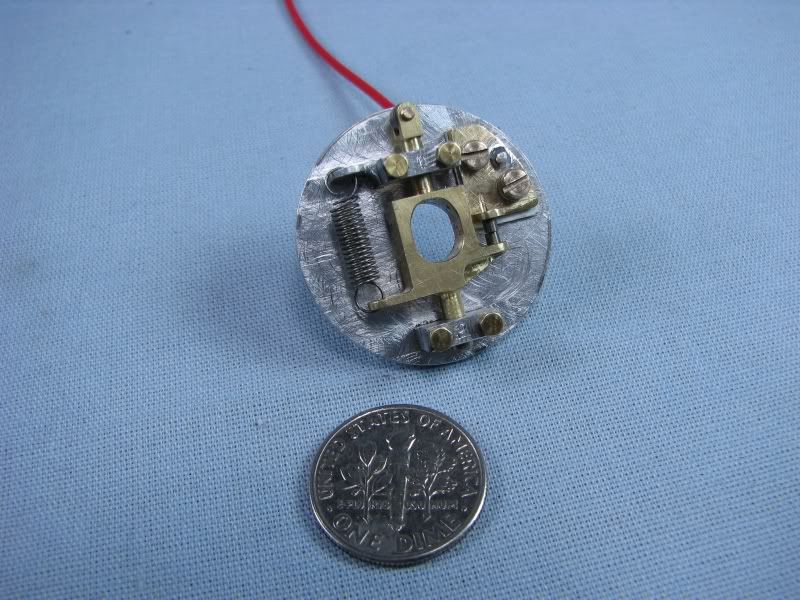
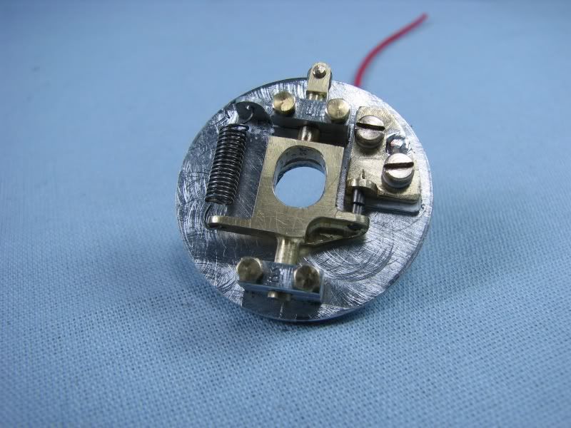
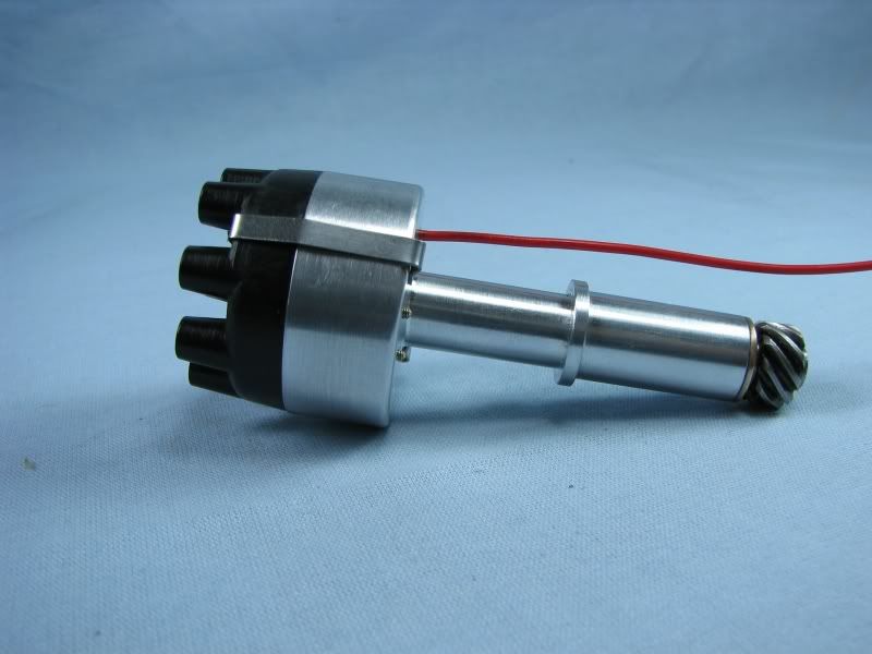
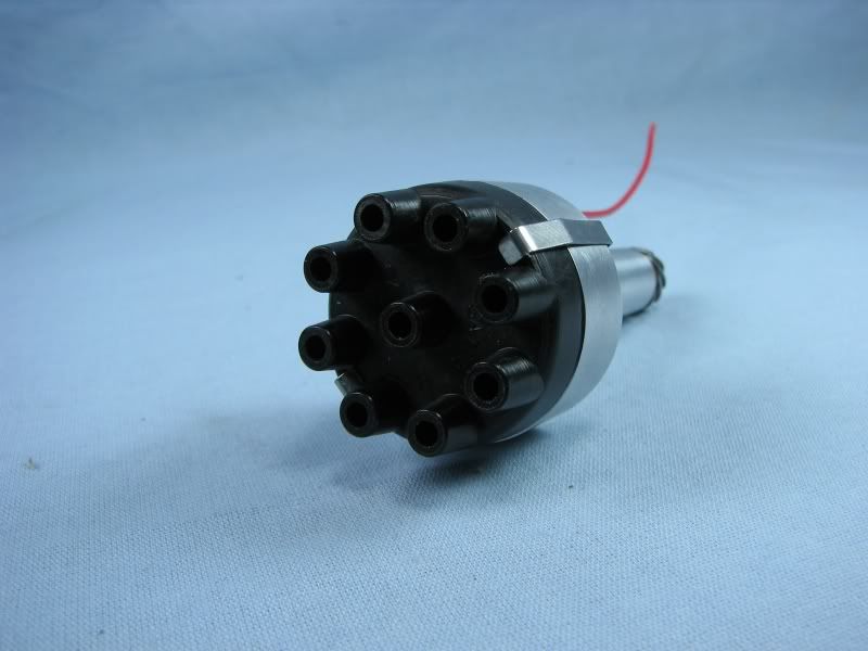
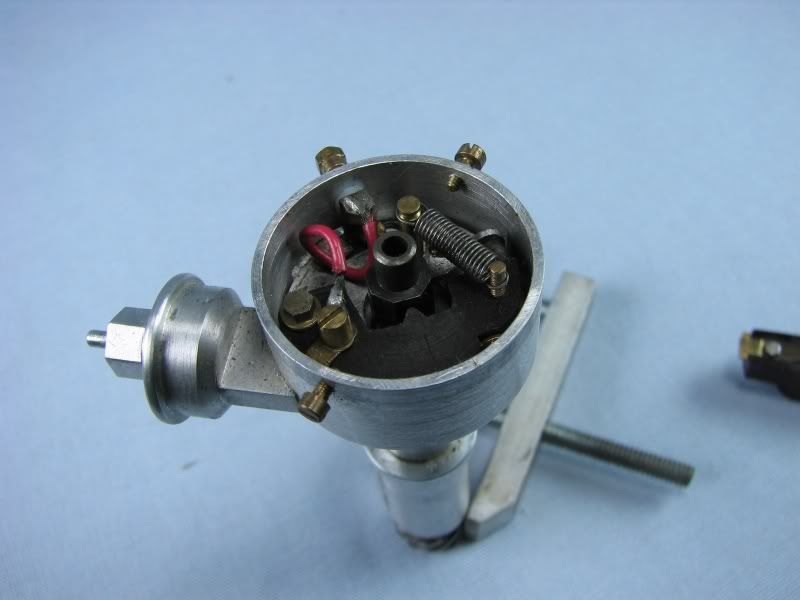
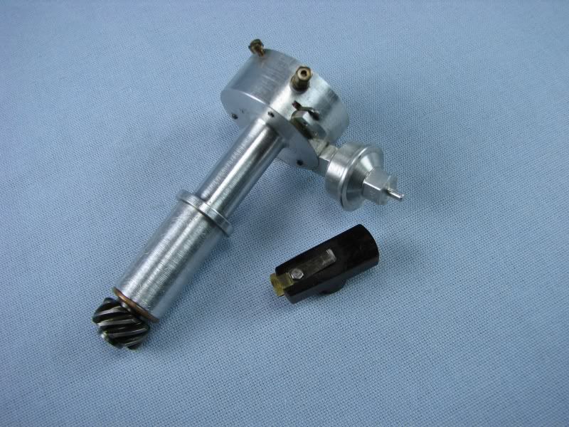
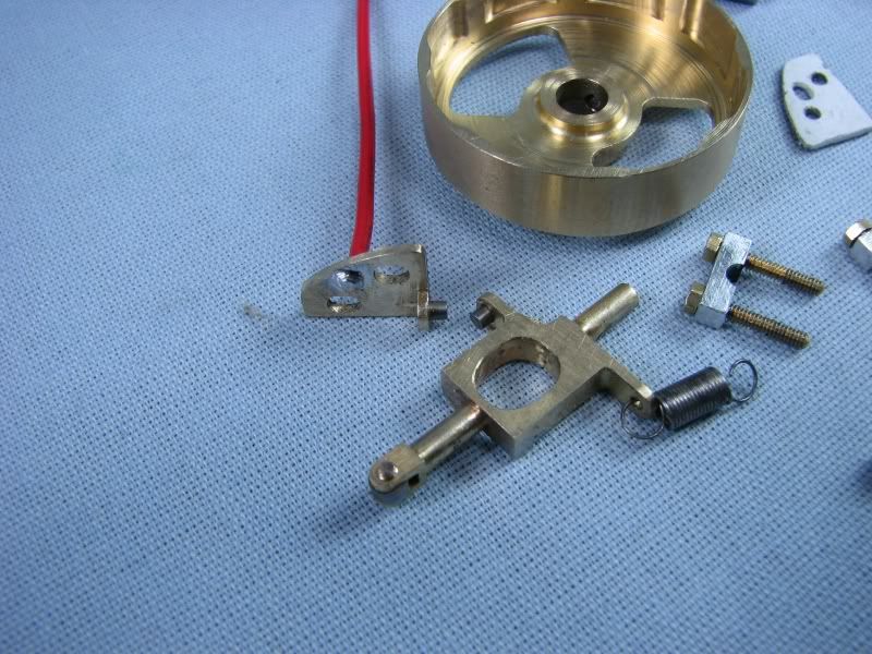
If you remember from the thread on my 302 Ford engine I mentioned that I had problems with the distributor, mainly because everything was too small. I had a set of points inside the dist. and with the limited space the cam to operate the points was so small that I had erratic timing along with not being able to get enough point opening, only about .012. It had been quite awhile since I ran the engine and enough people had asked to see it running that I went back to the drawing board to come up with a new dist. At first I was going to go with a Hall effect type trigger but not knowing how well I could get it to work given the size constraints I tried to think of some other way to make small points, operate them effeciently and keep the engine in time cylinder to cylinder. While thinking through the point, Hall effect options I came up with an outside cam disc similar to the vane window for the Hall effect trigger but it would operate a new design for the points. If this didn't work properly it wouldn't take much to go with the Hall effect, just something to hold the magnet and a new trigger wheel. I will be using an electronic ignition so the points could be made out of almost any material but to be sure to cover every possibility I used some tungsten pieces cut from a .062 TIG electrode. I put the electrode in my lathe and covered the ways with a piece of paper. I then started up the lather and using my Dremel with a diamond cutoff wheel cut several pieces .09 long, enough to press into the point arm and base and stick out about .06. After cutting I polished the ends with a fine diamond stick that I use for touching up my lathe tools. The moveable point arm is supported by two bearing blocks machined into the base plate and caps that go over them. The screws, 0-80, go through the bearing cap, base plate and screw into the distributor body to hold everything together. The moveable point also has a steel roller wheel on the end to follow the depressions in the cam disc. The fixed point has two elongated slots to make any adjustments needed for point gap. Unlike conventional points my moveable point is the ground side and the fixed point is insulated from the body and is my power side. I turned up two little shoulder bushings from plastic to go under the screw head and around the shank to insulate them. My hot wire goes out through the bottom of the distributor. Enough talk, here's some pictures. First are a couple of shots of the old distributor and the points and rotor.
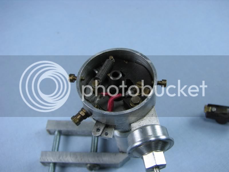
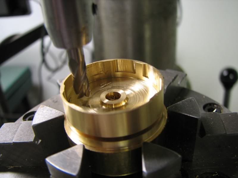
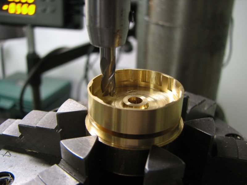
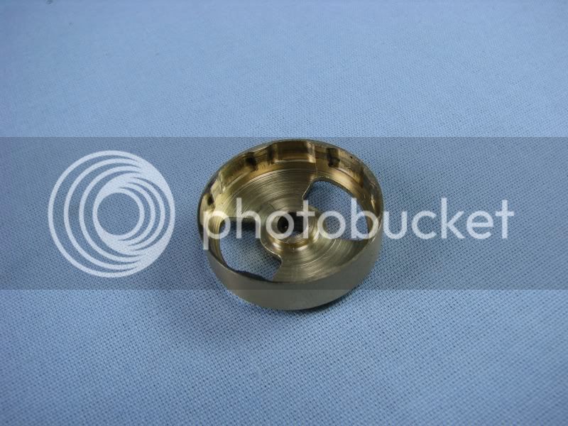
Next are a couple of shots of the cam disc that operates the points. I first drilled and reamed the center hole and then bored out the center area to the small diameter which would be the high point of the cam. I calculated the point closing area to have about 22 degrees of dwell. This came from a formula included with the instructions for the electronic ignition.
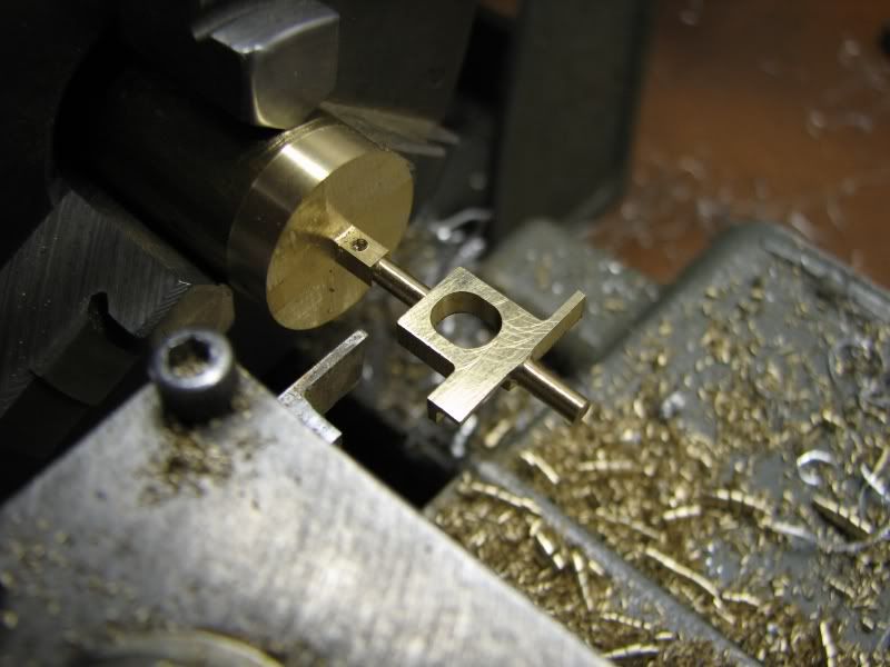
Next came the moveable point arm. I machined it from a piece of round stock. Making things this way always gives you a chucking piece instead of trying to figure out some way of holding it. After turning the first diameter, .093, I put it into my dividing head and cut the thickness, slotted the window and cut the remaining shape before putting it back in the lathe to cut the other round shaft. It then went back into the dividing head to cut the square on the end for the roller wheel to set into. It was then cut from the round stock, drilled for the point piece and spring, slotted for the roller wheel and cleaned up. It wasn't until later that I realized I had no way of keeping it aligned when operating so I soldered to little buttons on the bottom and filed them until it had just a couple of thou. clearance when mounted in the bearing blocks.

More to come.
gbritnell
Next are a couple of shots of the cam disc that operates the points. I first drilled and reamed the center hole and then bored out the center area to the small diameter which would be the high point of the cam. I calculated the point closing area to have about 22 degrees of dwell. This came from a formula included with the instructions for the electronic ignition.
Next came the moveable point arm. I machined it from a piece of round stock. Making things this way always gives you a chucking piece instead of trying to figure out some way of holding it. After turning the first diameter, .093, I put it into my dividing head and cut the thickness, slotted the window and cut the remaining shape before putting it back in the lathe to cut the other round shaft. It then went back into the dividing head to cut the square on the end for the roller wheel to set into. It was then cut from the round stock, drilled for the point piece and spring, slotted for the roller wheel and cleaned up. It wasn't until later that I realized I had no way of keeping it aligned when operating so I soldered to little buttons on the bottom and filed them until it had just a couple of thou. clearance when mounted in the bearing blocks.
More to come.
gbritnell