
You are using an out of date browser. It may not display this or other websites correctly.
You should upgrade or use an alternative browser.
You should upgrade or use an alternative browser.
Myford ML7 refurbisment and upgrade
- Thread starter Metal Mickey
- Start date


Help Support Home Model Engine Machinist Forum:
This site may earn a commission from merchant affiliate
links, including eBay, Amazon, and others.
Metal Mickey
Well-Known Member
- Joined
- Jul 5, 2008
- Messages
- 612
- Reaction score
- 6
BR, I was amazed at the amount of wear in the counter shaft itself! In fact I thought that the shaft was shaped with the inserts! It was easier than I thought to turn a new shaft and with new oilite bearings (at about £6 a piece cheaper to but than make -unless you already have the stock of course) and gave the the confidence to renew the other shafts (incluging the leadscrew!). I may be tempted to check your countershaft and maybe turn a new one which will help with your pulley problem..... Thanks for the health equiry, can get out for a nother couple of days but there are many, many worse off than I am, but thanks for asking.baldrocker said:MM
Strange how the emphasis moves from making chuff chuffs to making tooling and
refurbishing machinery.
Having great fun working on the beast (just think how dull it would be to just
go out and buy a new one) although as I go further
more and more becomes apparent. Latest is a wobble in the countershaft pulley
makes the motor bounce up and down about 3/16" which in turn shakes
the whole lathe. Sourced a new pulley that needs to be bored to fit shaft,
difficult to do if some dodo has removed the original one. Must go back
and read your post from the start. Hows the health?
Regards
BR
lathe nut said:Metal Mickey, Lathe Nut came easy when my wife called me that because I have several lathes, but I don't spend my money or time anywhere but work and home, after I get want she wants done and the yard work its in the shop I go, I live in the USA and got all the chrome on the machine done for one hundred dollars, it is a German built machine, great quality in it, its a Steniel, you machine is coming along nice, sure is a lot of fun getting them in shape to get the dirty, have fun, Lathe Nut
Lathe nut (still love that name!) and Dave, unfortunately I was born without the tidy gene so don't worry, it will soon look 'normal' for me, although I will try and do better (New Years resolution!) but don't hold out too much hope.
Thanks for the interest, really appreciate it. MM
Metal Mickey
Well-Known Member
- Joined
- Jul 5, 2008
- Messages
- 612
- Reaction score
- 6
Today I managed to finish turning the last shaft, which fits between the leadscrew and the gear to turn the leadscrew itself. The joining adaptor was also bored and reamed to fit the new shaft. All that now remains to do on the leadscrew assembly is to mill the long slot on the recently completed shaft, and drill a couple of holes for roller pins and glue the joints.
The last few items to be assembled showed up more items that really should be replaced. The two under saddle plates in particular. Also no shims existed and these would definitely need to be installed. I could not locate the leadscrew nut for the cross slide and am not sure it was even there when the lathe arrived. So it was a case of phoning Malcolm at Myfords and make my third and hopefully final order. which means that whilst I should definitely
complete the refurbishment in the sense of making new parts, the final assembly will have to wait upon the delivery from Myford.
It seems that it was a good job I phoned Malcolm as he very kindly explained the method of shimming the saddle. There are 5 shims needed and at just under £5 a piece they are not cheap at first sight. However they are made up of various layers and they can be stripped off to get the right size. I will do a write up of the procedure on my main website with photo's (fingers crossed!) next week and it is not simply a case of putting them between the
plates and the saddle (I also took the opportunity of buying two new plates as well).
I did however use the Myford lathe for the very first time today! It may only have been to clean up the end of the new shaft from burr's but it was used!
When the project is complete I will list the costs incurred and an approximation of the time taken. It may make 'interesting' reading.
Maryak
Well-Known Member
- Joined
- Sep 12, 2008
- Messages
- 4,990
- Reaction score
- 77
Mike,
Great progress. :bow:
It never ceases to amaze me how, just when you think your there, up pops another small but very annoying problem, which leads ever onward.
I am sure Dave is right, your lathe will be envied by many of us when it is completed.

Oh, congratulations on making your first swarf with it.

Best Regards
Bob
Great progress. :bow:
It never ceases to amaze me how, just when you think your there, up pops another small but very annoying problem, which leads ever onward.
I am sure Dave is right, your lathe will be envied by many of us when it is completed.
Oh, congratulations on making your first swarf with it.
Best Regards
Bob
Metal Mickey
Well-Known Member
- Joined
- Jul 5, 2008
- Messages
- 612
- Reaction score
- 6
Many thanks Bob, that is a great compliment and much appreciated. :bow:
Metal Mickey
Well-Known Member
- Joined
- Jul 5, 2008
- Messages
- 612
- Reaction score
- 6
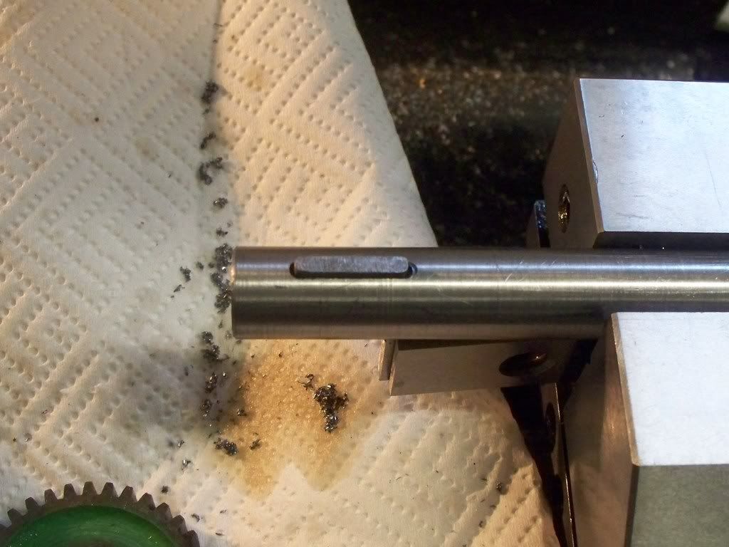
Today I have almost completed the Myford leadscrew. All that is left is to drill the two holes at 90° to each other to locate the two spring roller pins.
The first task this morning was to mill the small 1/8 slot to for the gear drive pin to locate in. I got into a mental mess with including, excluding, dividing the end mill in half to measure the length of the cut. However it must be because I am finally learning that a light first cut showed me the way although there is a slight overcut on the top cut. The rest of the milling job went well and the pin fitted just right, allowing a gear to fit snugly in place (see photo).
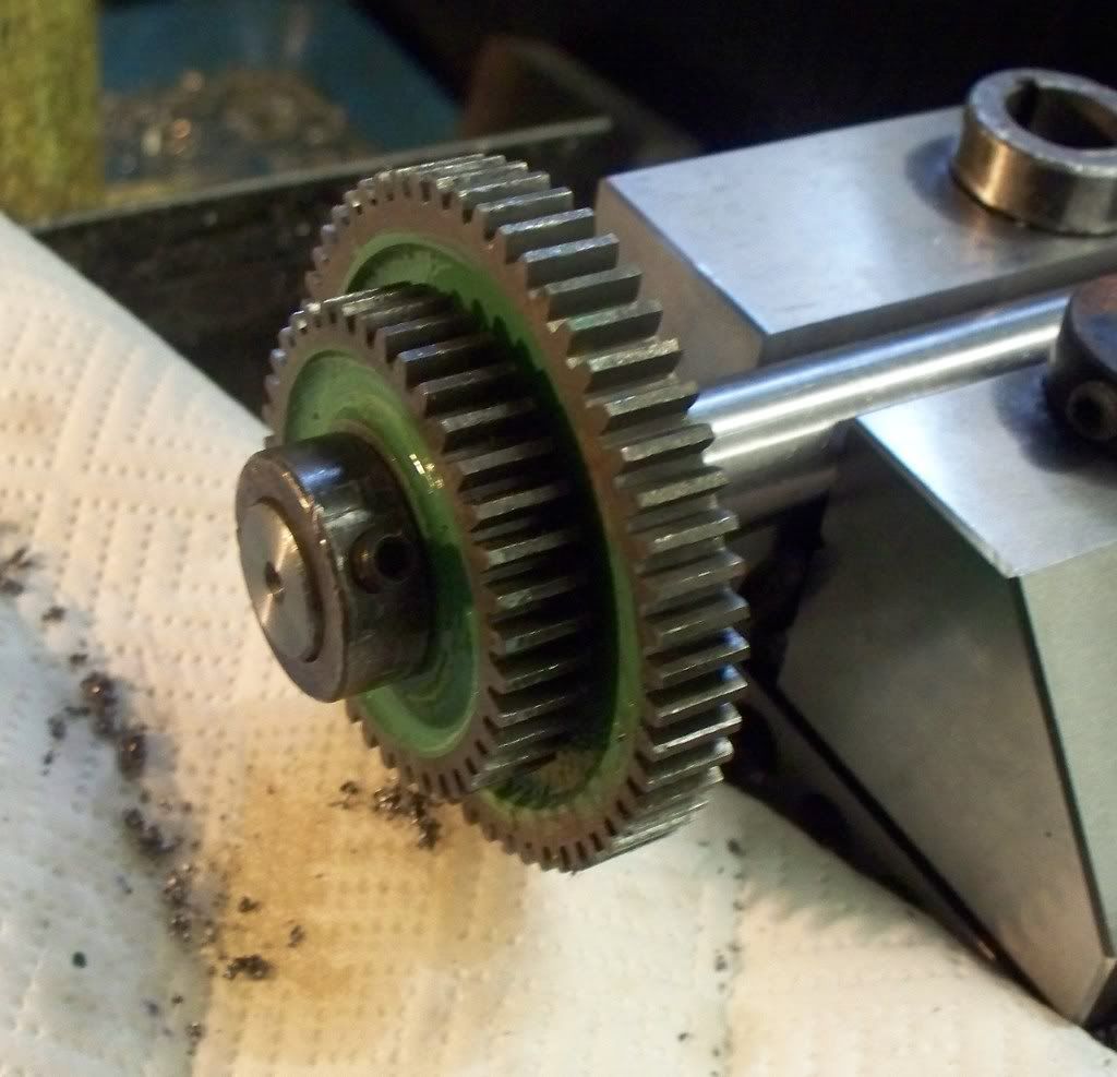
The next job was to set up the whole leadscrew and work out the position of the joint so the length would be correct. In fact it didnt need sorting and I suppose I can thank Myford for that. Since I made the constituent parts to the same dimensions as the original, all the parts fitted as they should.
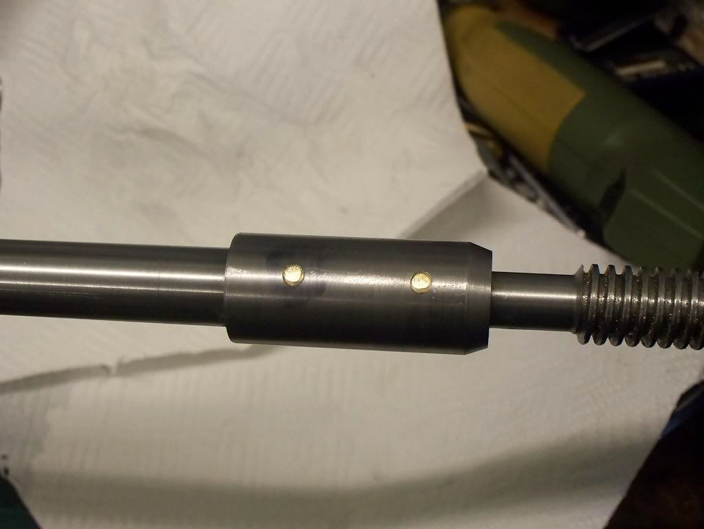
One headache less, I decided that the best way forward would be to clean the end of the leadscrew, the right hand shaft and the joint piece. I then used Delta 55 high strength retainer adhesive to hold the three pieces together and tomorrow that should help when I pin them.
I must admit I dont have a great deal of confidence when gluing metal. It doesnt seem right, although I know industry relies on adhesive in a great many situations. Its only time and experience I suspect before I gain that confidence as I have read many articles where model engineers rely on such adhesives.
The post lady then turned up with a nut for the cross slide only ordered yesterday! Many thanks Malcolm. So as soon as the other outstanding items arrive, the lathe refurbishment will be complete. I have enjoyed the rebuild far more than I ever thought.
I shall have to be very careful I dont buy another .. (no, no !!!!!!!!!)
The first task this morning was to mill the small 1/8 slot to for the gear drive pin to locate in. I got into a mental mess with including, excluding, dividing the end mill in half to measure the length of the cut. However it must be because I am finally learning that a light first cut showed me the way although there is a slight overcut on the top cut. The rest of the milling job went well and the pin fitted just right, allowing a gear to fit snugly in place (see photo).
The next job was to set up the whole leadscrew and work out the position of the joint so the length would be correct. In fact it didnt need sorting and I suppose I can thank Myford for that. Since I made the constituent parts to the same dimensions as the original, all the parts fitted as they should.
One headache less, I decided that the best way forward would be to clean the end of the leadscrew, the right hand shaft and the joint piece. I then used Delta 55 high strength retainer adhesive to hold the three pieces together and tomorrow that should help when I pin them.
I must admit I dont have a great deal of confidence when gluing metal. It doesnt seem right, although I know industry relies on adhesive in a great many situations. Its only time and experience I suspect before I gain that confidence as I have read many articles where model engineers rely on such adhesives.
The post lady then turned up with a nut for the cross slide only ordered yesterday! Many thanks Malcolm. So as soon as the other outstanding items arrive, the lathe refurbishment will be complete. I have enjoyed the rebuild far more than I ever thought.
I shall have to be very careful I dont buy another .. (no, no !!!!!!!!!)
Metal Mickey said:Today I have almost completed the Myford leadscrew. All that is left is to drill the two holes at 90° to each other to locate the two spring roller pins.
What two spring roller pins. ??
JS
DickDastardly40
Well-Known Member
- Joined
- Oct 23, 2007
- Messages
- 309
- Reaction score
- 0
Metal Mickey said:
Micky,
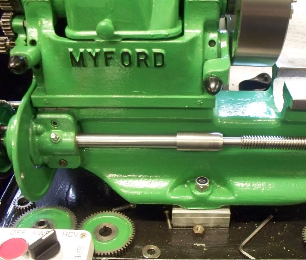
Please take this in the spirit intended as I think you've done a marvelous job........The holding down bolt isn't long enough as the nyloc nut in the picture above hasn't engaged the nyloc portion so It 'could' vibrate undone. I'd use a washer too.
If you have this covered or have mentioned it elsewhere, then I apologise, just thought it best to mention it.
I like the green, better than mine's battleship grey.
Al
Metal Mickey
Well-Known Member
- Joined
- Jul 5, 2008
- Messages
- 612
- Reaction score
- 6
John Stevenson said:What two spring roller pins. ??
JS
John, it may be the age of the machine (many things do not line up with the manual) built 1953, or a previous update (several items looked if they have been bodged(sorry refurbished) before) but when it arrived it had the leadscrew as shown earlier. That had a connecting piece as per my replacement and both the leadscrew and right hand shaft were held in position by roll pins.
I have just remade the parts to the same pattern as found (know no different as this is my first ML7) None of old parts had woodruff keys (which I had bought from Myford prior to taking it all apart) which may be a way they were made later. The manual shows a completely different leadscrew right hand side to mine............
---------------------------------------------------------
Al,
Re:
Micky,
Please take this in the spirit intended as I think you've done a marvelous job........The holding down bolt isn't long enough as the nyloc nut in the picture above hasn't engaged the nyloc portion so It 'could' vibrate undone. I'd use a washer too.
If you have this covered or have mentioned it elsewhere, then I apologise, just thought it best to mention it.
I like the green, better than mine's battleship grey.
Al
No problem and know offence taken. The hold down bolts have yet to be secured. All I have done so far is drill the holes in the raised blocks and bench tray. When the lathe has been completed (very soon....) they will have the washer (an a spring washer underneath) and be secured subject to the turning test to make sure the bed doesn't twist. I didn't want to secure it yet until all the parts had been replaced without any strain on the lathe at all. What you can't see is about 6" of rod underneath as they have yet to be trimmed to size. They will need this as there are other fittings to be done underneath.
If you hadn't have pointed the issue out Al, someone may have thought this was correct so giving me the opportunity to explain may help someone in the future........MM
I guessed as much as where they went.
This early design was the best one they did, later designs had a one piece leadscrew and if you had a snarl up they stripped something and did some serious damage.
Later Super 7's had tufnol tumbler gears fitted for quietness and as a fuse, these struipped if you crashed [ and made Myfords more money for replacements.
If you replace the roll pins with parallel brass pins they will do the same job and also shear in the case of a fowl up.
One or even two replacement brass pins will only set you back minutes but save a lot of money and hassle.
JS.
Metal Mickey
Well-Known Member
- Joined
- Jul 5, 2008
- Messages
- 612
- Reaction score
- 6
John, many thanks for the history and also the brass pin idea. Excellent timing as I planed to do the pin job tomorrow if I am up to it (supposed to do it today!). I just hope the adhesive I put in doesn't do its job now! I'll bet its the only time it will work!
Anyway I will definitely put brass pins in. I was thinking about 1/8th (0.125") diameter, I don't want to go to big, or small. What do you think?
MM
Anyway I will definitely put brass pins in. I was thinking about 1/8th (0.125") diameter, I don't want to go to big, or small. What do you think?
MM
Peter Neill
Well-Known Member
- Joined
- Sep 19, 2008
- Messages
- 69
- Reaction score
- 0
That's exactly what I did on my leadscrew.
IIRC the pins I made were around 4mm diameter, but I 'waisted' them down in the middle.
Here's a picture of the old and new leadscrews, and you can just make out the brass pins.
http://tinyurl.com/cqvuub
Peter
IIRC the pins I made were around 4mm diameter, but I 'waisted' them down in the middle.
Here's a picture of the old and new leadscrews, and you can just make out the brass pins.
http://tinyurl.com/cqvuub
Peter
Metal Mickey
Well-Known Member
- Joined
- Jul 5, 2008
- Messages
- 612
- Reaction score
- 6
Peter Neill said:That's exactly what I did on my leadscrew.
IIRC the pins I made were around 4mm diameter, but I 'waisted' them down in the middle.
Here's a picture of the old and new leadscrews, and you can just make out the brass pins.
http://tinyurl.com/cqvuub
Peter
You beat me to it Peter, I was going to email you to say many thanks for the tip and contact for suitable replacement leadscrew. So thanks. MM
Metal Mickey
Well-Known Member
- Joined
- Jul 5, 2008
- Messages
- 612
- Reaction score
- 6
For the second day running I didnt manage to stay out in the workshop for as long as I would have liked. However I did manage to pin the leadscrew and fit it permanently to the lathe so that was a positive. Even better was the smooth and free turning nature of the leadscrew after final fitting.
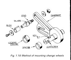
I decided that to cheer myself up, I would connect up the gear train and run the lathe at various speeds to run in the new bearings of the counter shaft and leadscrew. However I was soon to discover that the gear wheel changing on this 1953 version of the ML7 had a really frustrating gear change set up! On my much loved ML10 (and the same for the ML7 according to the later manual I have) you simply unscrewed the retaining screw on the end of the pillar on which the gears seat. Not so my lathe! The screws on the end are in fact bolts on mine. They fit into two bolts with indents that fit into the rear of the gear casting. The hollow pillar through which the bolt goes then has another keyed bush that fits inside the keyway cut gear. The length of the pillar is more than the width of two gears and the screw is the same outside diameter as the inner pillar. So if you want to change gears you have to take the whole bolt, pillar and special nut off the casting. Since there isnt a lot of room between the casting and the lathe body this is a fiddly (bl*&^^y frustrating!!!!) job.
I now understand why many owners either bought or built gearboxes! I will have to sort the problem out, but for now I have packed the gap with two large washers to fill the gap (about 3/16) and a smaller washer for the bolt head to seat against. This works fine but it isnt an engineered solution (see I am getting posh now). It may be a simple case of reducing the overall diameter of the pillars (cant see that Myford would have allowed this situation so there must be something wrong let me know) or buying a pair of modern replacement fittings from Myford.
It may be just a bodge from a previous owner which I suspect is the true reason for the discrepancy. However the gears were eventually fitted after discovering my driver gear may be an accessory rather than the standard gear. After much head scratching I found a set of gears that I had and would give a fine feed. I need another gear to get the finest feed, but I just wanted to get the leadscrew to turn over for now.
And turnover it did, after all the oil nipples were given a generous amount of Myford recommended oil I rand the motor on a slow speed at first, in both forward and reverse directions, before speeding up, then varying the speed. The whole gear end of the lathe (I believe the tumbler gears are known for there noise) is a lot noisier than my ML10 . However that may change with the gear cover on.
The leadscrew seemed to run as true as it should with the naked eye. So I would consider the whole exercise a success in regard to making the new shafts and leadscrew. My thanks go to members of the HMEM forum for their ideas and support during this project and in particular to Peter who told me about a supplier for the leadscrew threaded rod. Whilst it is not finished, all the large engineering tasks have been done leaving just a few items outstanding waiting for parts from Myford. I would say it is 90% finished and less than a days work left.
This is what the stub should be like.
RDG sells these as well as Myford, don't know what the quality is.
if the keyed sleeve is Ok and that's the hardest part the rest can be made easily.
What about Jim Marshall who sells the Myford gear on Ebay, he's OK to deal with.
JS.
RDG sells these as well as Myford, don't know what the quality is.
if the keyed sleeve is Ok and that's the hardest part the rest can be made easily.
What about Jim Marshall who sells the Myford gear on Ebay, he's OK to deal with.
JS.
Metal Mickey
Well-Known Member
- Joined
- Jul 5, 2008
- Messages
- 612
- Reaction score
- 6
Thanks again for the info Steve. Those you show are the same as on my ML10. I didn't know that RDG did them or the eBay contact. I have been thinking since I made the post that I would go the replacement route but it shouldn't be beyond the wit of man so to speak to make them. Its down to time I think, if they are not to dear. I have so many thing I want to do and limited time so perhaps that is the best route.
Thanks Steve.
Just checked eBay and there is a set from Lathe parts but with postage they are £26. May reconsider the build/modify route!
Thanks Steve.
Just checked eBay and there is a set from Lathe parts but with postage they are £26. May reconsider the build/modify route!
Metal Mickey
Well-Known Member
- Joined
- Jul 5, 2008
- Messages
- 612
- Reaction score
- 6
Lota of money! A piece of stainless steel bar looks inviting in the morning! It shouldn't take too much to make...
Metal Mickey
Well-Known Member
- Joined
- Jul 5, 2008
- Messages
- 612
- Reaction score
- 6
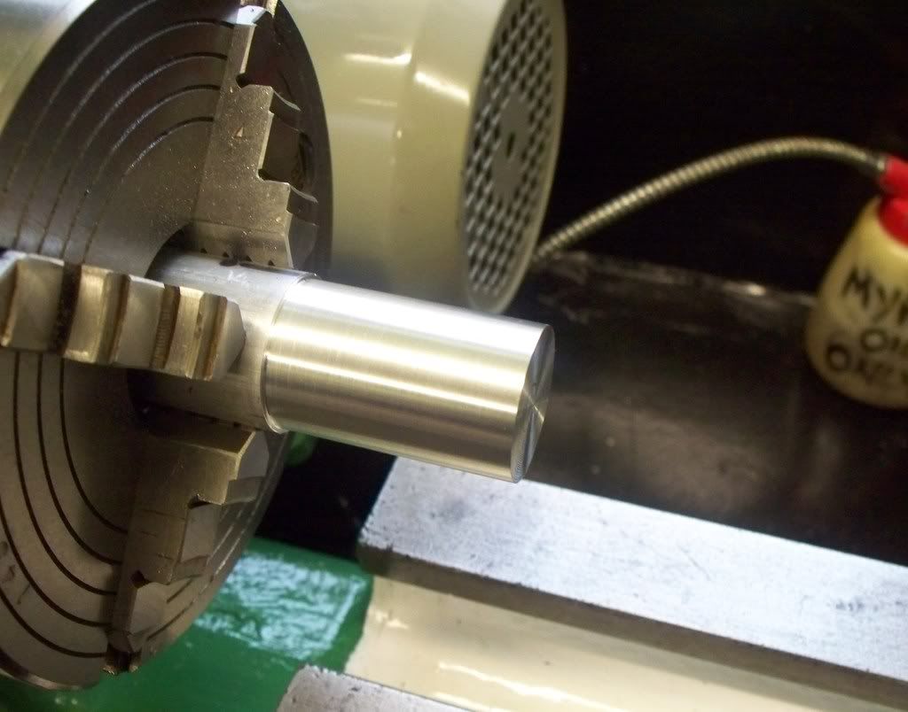
Well I am pleased to say the Myford ML7 lathe refurbishment and rebuild has been completed! My first piece of metal bar has been turned (see photo) successfully if nervously.
There are a few items still to be done but other than bolting the lathe down, they are just adjustments. Such as the main motor belt guard is catching the large pulley somewhere and the gear guard wont go on because of the top filling/storage cabinet doesnt give enough clearance when the gears are fitted.
I also have decided to make a new steel tool post and holder system as I have on my other lathe and two new gear studs as fitted to my ML10 and later ML7 lathes. Then there are the drawers and front door for the bench below and that should be about it. None of which stops me from using the lathe however the next job will be to bolt the lathe down and use the test procedure to make sure the lathe turns true before any serious work is started or done. However I must admit to a little smile at the smooth cutting of the aluminum .
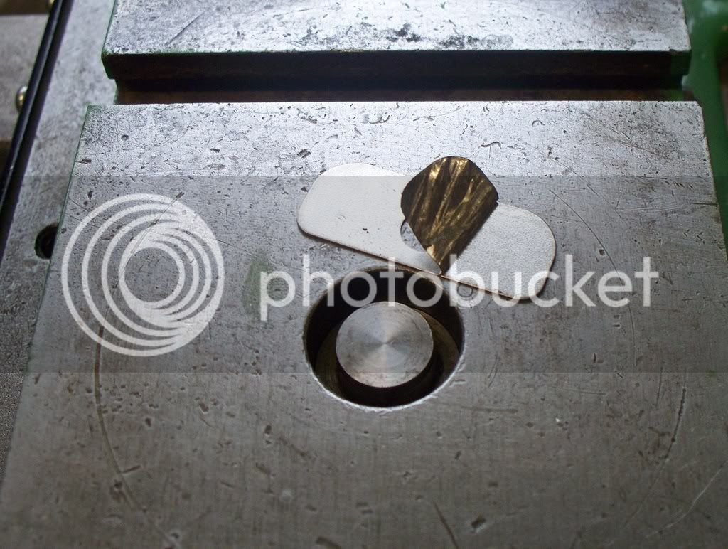
Today started with the fitting of the parts recently arrived from Myford (although some will have to go back as they are not correct). Starting with the fitting of the saddle and using the clever shims that cost around £5 each! Malcolm, from Myford told me when I ordered the parts that the shims come apart at around 0.015 a layer. They are separated by flicking the edge of the shim and then the layer pulled off.
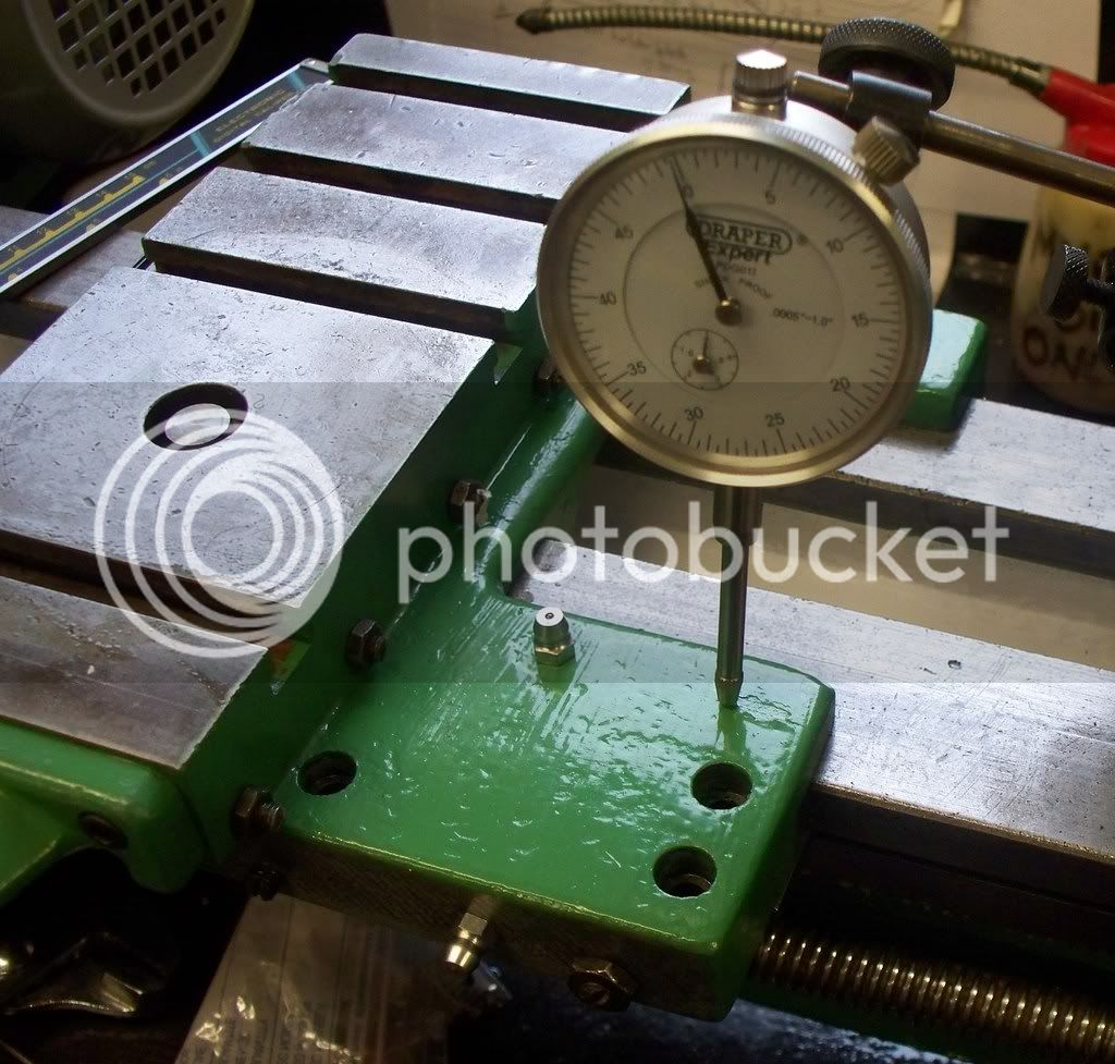
To shim the saddle you start at the back right hand side and using a dial indicator measure how much movement you get if trying to lift the saddle. The aim is to get under 0.0015 movement all around. The first attempt saw the saddle fit within the tolerance level set, however when trying to move the saddle the length of the available lathe bed, it became stiff when moving toward the tailstock. My immediate thought was the bed being worn more than I thought. Before making any further adjustments I remembered that I had only adjusted the saddle gib strip approximately and after a proper adjustment the saddle moved freely across its range with only about 0.001 movement of the saddle on the right hand front side.
With the saddle adjustment made the next job was to adjust the top slide and cross slide and then with a little trepidation I chucked some bar and made the cuts. I have enjoyed the refurbishment although I will be glad to get back to making the Seal 4 cylinder engine but that may have to wait for a few days since I will be helping my brother, Steve, with sorting our fishing boat out after all the smoke and oil that escaped from the engine after our last trip! If you want to know more follow this link to our Dartmouth fishing site http://www.dartmouthfishing.co.uk
If you are considering refurbishing your Myford then all I would say is go for it! Malcolm and Sarah at Myfords are a great help.
There are a few items still to be done but other than bolting the lathe down, they are just adjustments. Such as the main motor belt guard is catching the large pulley somewhere and the gear guard wont go on because of the top filling/storage cabinet doesnt give enough clearance when the gears are fitted.
I also have decided to make a new steel tool post and holder system as I have on my other lathe and two new gear studs as fitted to my ML10 and later ML7 lathes. Then there are the drawers and front door for the bench below and that should be about it. None of which stops me from using the lathe however the next job will be to bolt the lathe down and use the test procedure to make sure the lathe turns true before any serious work is started or done. However I must admit to a little smile at the smooth cutting of the aluminum .
Today started with the fitting of the parts recently arrived from Myford (although some will have to go back as they are not correct). Starting with the fitting of the saddle and using the clever shims that cost around £5 each! Malcolm, from Myford told me when I ordered the parts that the shims come apart at around 0.015 a layer. They are separated by flicking the edge of the shim and then the layer pulled off.
To shim the saddle you start at the back right hand side and using a dial indicator measure how much movement you get if trying to lift the saddle. The aim is to get under 0.0015 movement all around. The first attempt saw the saddle fit within the tolerance level set, however when trying to move the saddle the length of the available lathe bed, it became stiff when moving toward the tailstock. My immediate thought was the bed being worn more than I thought. Before making any further adjustments I remembered that I had only adjusted the saddle gib strip approximately and after a proper adjustment the saddle moved freely across its range with only about 0.001 movement of the saddle on the right hand front side.
With the saddle adjustment made the next job was to adjust the top slide and cross slide and then with a little trepidation I chucked some bar and made the cuts. I have enjoyed the refurbishment although I will be glad to get back to making the Seal 4 cylinder engine but that may have to wait for a few days since I will be helping my brother, Steve, with sorting our fishing boat out after all the smoke and oil that escaped from the engine after our last trip! If you want to know more follow this link to our Dartmouth fishing site http://www.dartmouthfishing.co.uk
If you are considering refurbishing your Myford then all I would say is go for it! Malcolm and Sarah at Myfords are a great help.


Similar threads
- Replies
- 14
- Views
- 918
- Replies
- 61
- Views
- 8K