Myford ML7 refurbisment and upgrade

Home Model Engine Machinist Forum

Help Support Home Model Engine Machinist Forum:

This site may earn a commission from merchant affiliate links, including eBay, Amazon, and others.

Metal Mickey

Well-Known Member
Joined
Jul 5, 2008
Messages
612
Reaction score
6
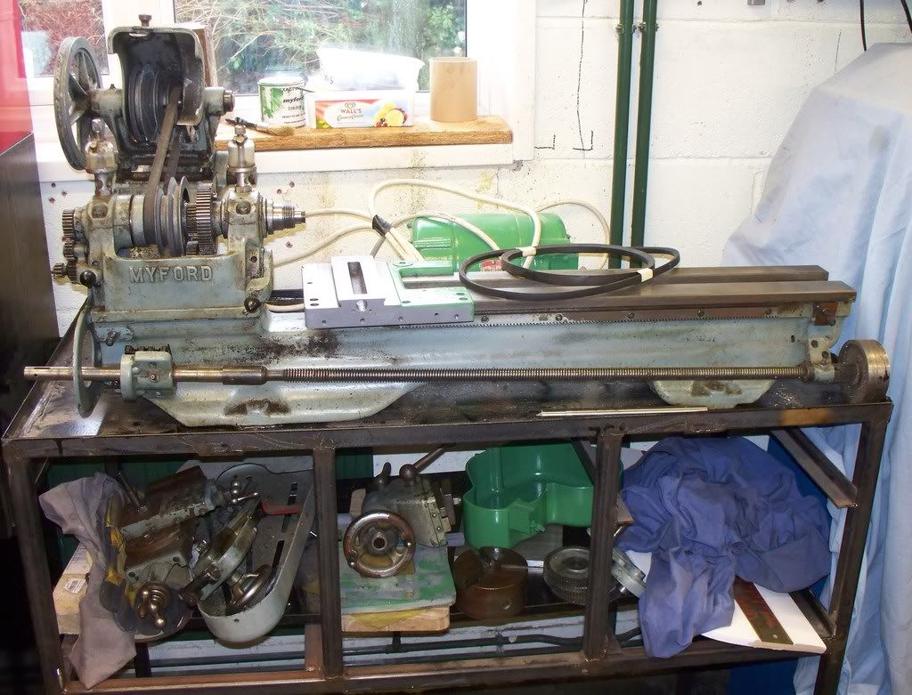
I have at last started on the refurbishment of my speculative purchase of a Myford ML7 lathe on eBay last February. With the recent sale of my Myford ML10 I had the space for the lathe to go into and the funds to carry out the refurbishment and upgrade.

My intention is to have a Myford with variable speed motor and digital readouts that will outlast me. Time will tell.

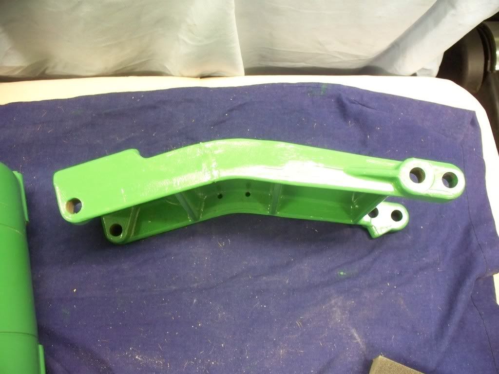
Today it was back to the paint brush and a bit of a surprise. The high quality paint brush I had been using did ok, but I thought the paint lay on a little thick at times. Today, because of the smaller mature of the items to paint, I got out a smaller artist type brush from a cheap set bought on the internet. The surprise was in the quality of finish. The cheap artist brush was gave a far better finish!

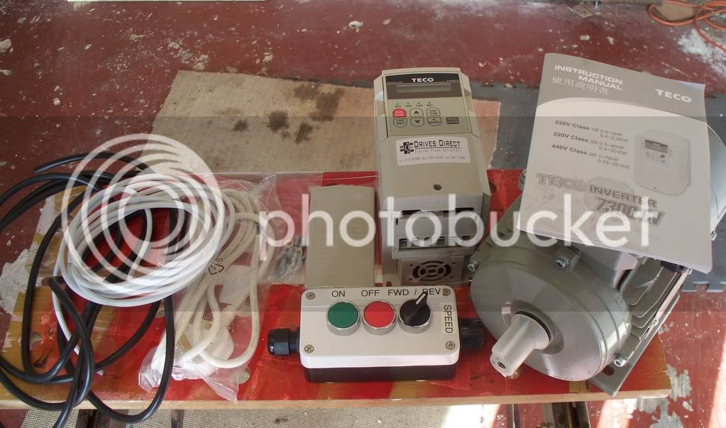
Yesterday I ordered the new electric motor, inverter and remote control and today it arrived! Good service so far. The package
also included three electric cables and some end fittings so a little study will be needed before it all goes together. I will let you
know how it goes.

The latest edition of Model Engineering Workshop arrived yesterday and included an article of a rev counter that seems a
possibility for the ML7. Again if I go ahead with making one I will let you know how I get on.

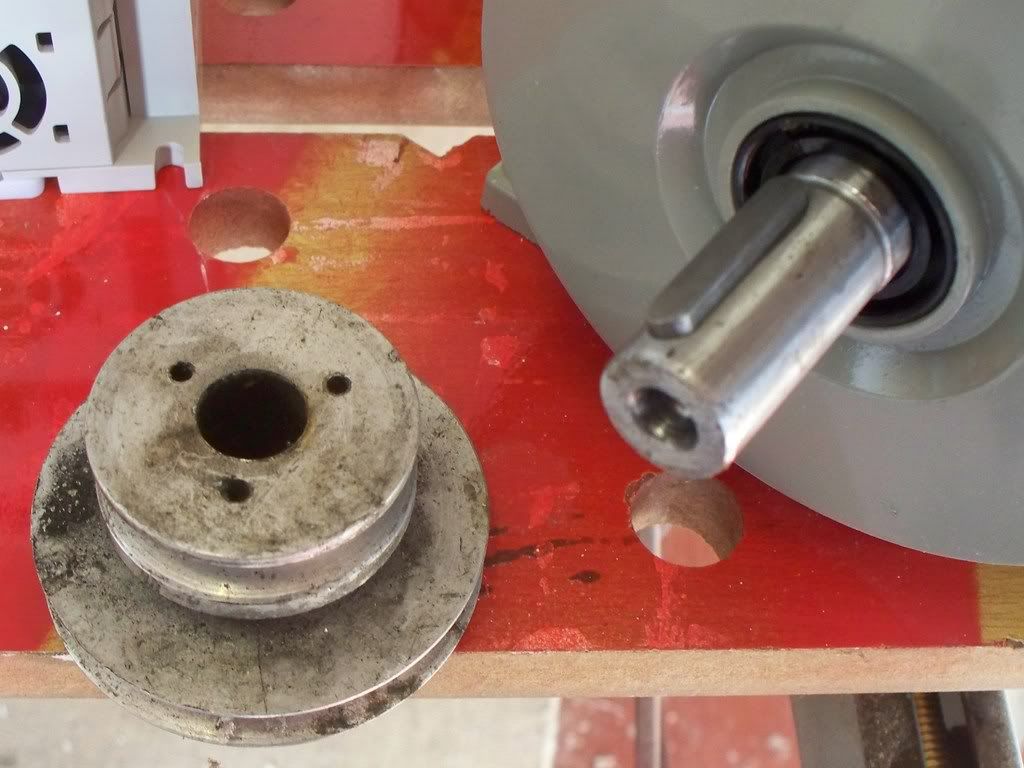
After the excitement of unpacking the new motor I then hunted around for the pulley that fitted the old motor. Needless to say
the bore of the pulley didn't match the new motor but fortunately the shaft is larger than the bore so its just a case of boring out the pulley and cut a keyway. Something I have yet to do.

With so many parts laid out around the workshop drying and the new motor unpacked, I thought it was time for a cup of tea, and a new list of action points. So the following list is the next phase of the refurbishment. I will let you know how I get on.

I am now waiting for some handles from RDG Tools online and various items for Myford themselves.

I must be honest I am really enjoying this refurbishment project, surprisingly so. I am treating the ML7 as a big set of castings and it's a good way to look ait I think. More to follow…..

List of actions for Myford ML7 refurbishment 20th January 2009

1. Machine up an new counter shaft
2. Machine up a new leadscrew front shaft
3. Machine new phosphor bushes for leadscrew
4. Make new drawers for lathe bench
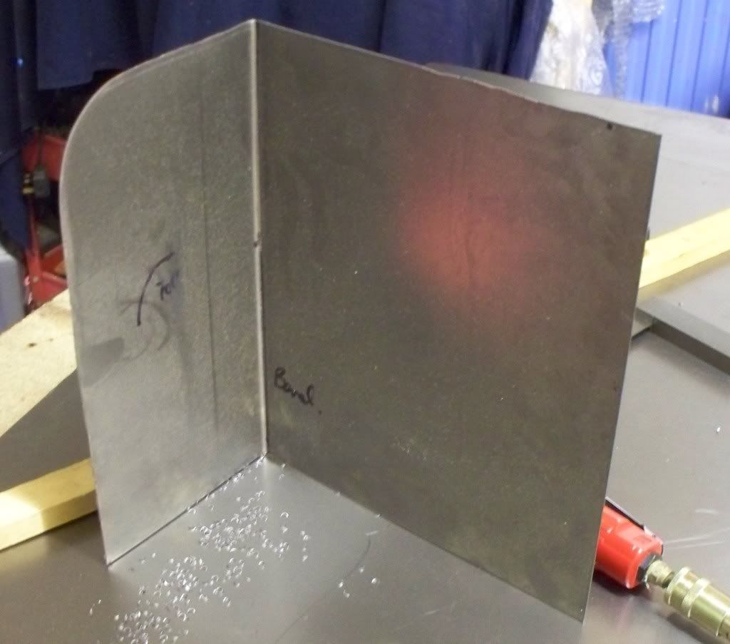
5. Make a sheet steel back and side plate for lathe bench
6. Make two raised blocks for lathe to stand on
7. Paint remaining front part of lathe bench with black hammerite
8. Make and fit front door to bench (either wood or sheet metal)
9. Make and fit shelves for lathe bench
10. Bore out and cut a keyway for new lathe motor
11. Make the rollers for the bench drawers to fit on
12. Fly cut top slide tool post area
13. Clean up and paint the leadscrew right hand side handle
14. Wire up and fit new electric motor
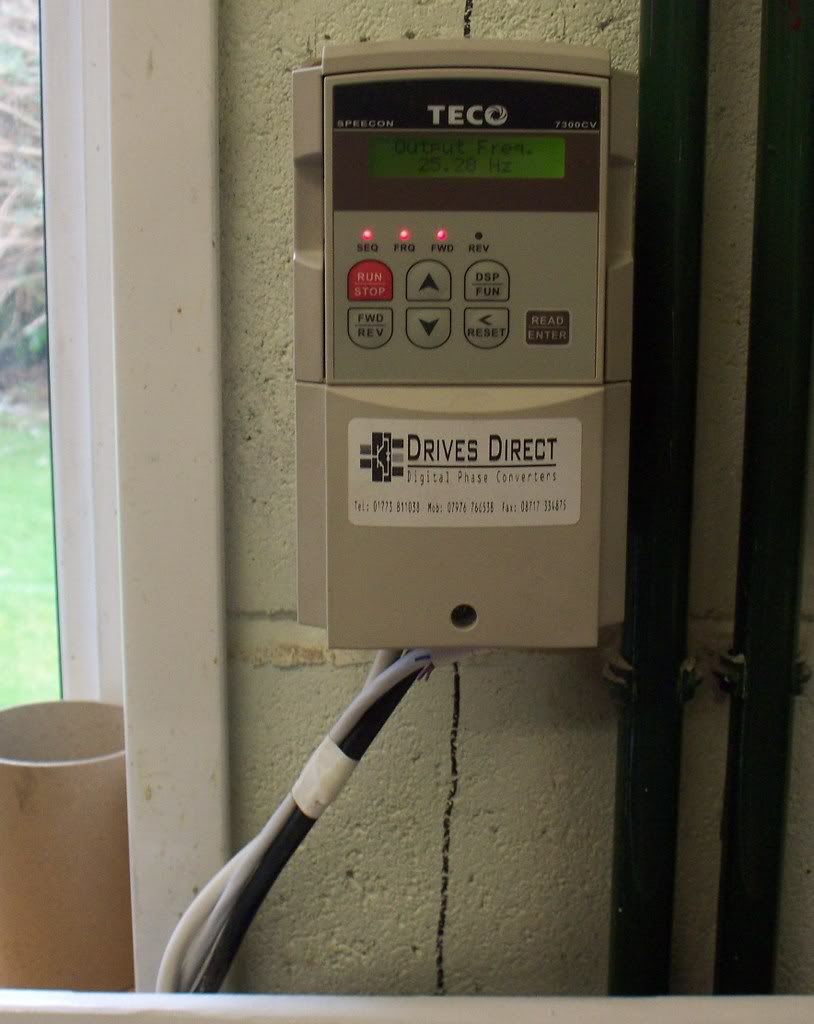
15. Wire up and fit new inverter
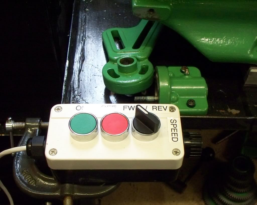
16. Wire up and fit remote (after giving some thought to position)
17. Check eBay for the following (new or good secondhand):-
a. Rear tailstock handle
b. Long cross slide

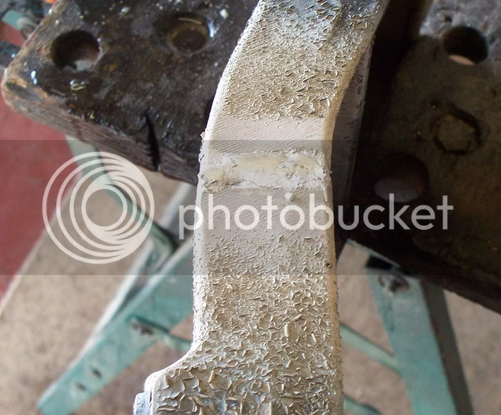
I will let you know how I get on.......and here are some pictures of the 'before' bit.....

myfordrefurbishment20012009012.jpg


The variable speed package........

myfordrefurbishment20012009002.jpg


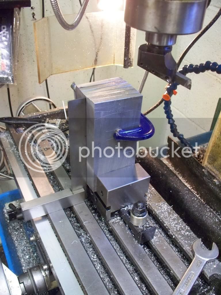
I need to bore out the pulley...................

myfordrefurbishment20012009009.jpg

 
Mike,

This is a pretty big project you have embarked on. :bow:

I am sure you will achieve both success and many warm fuzzies when it's finished.

Best Regards
Bob
 
Life is never dull Bob! Its not until you pull a lathe apart that you realise how many bots there are! One advantage with digital camera's is the photo's you can take BEFORE you unscrew something.........just hope I don't loose the laptop!
 
The first major task today was to have a go at welding Aluminum for the very first time. I used the Durafix system which is advertised as being simple to use.

Well we have all heard that before and I must admit to some skepticism as I prepared to have a practice on a couple of scrap aluminum pieces. I decided to make one edge of each have a chamfer so giving me a v to fill. The process involves cleaning up the part to be welded with the supplied stainless steel wire brush. Then the parts need to be brought to the temperature at which the welding rods will melt when in contact with the metal, and not the flame of the propane.

Here is where I learnt an important (and obvious now) fact that there is a considerable amount of heat required to get the metal to the 700 °plus needed. The great amount of heat is made worse by holding the parts to be welded together in the vice. As we know aluminum is a great conductor of heat so you end up heating the parts plus the iron vice!

Well when the heat was eventually reached the welding rod was rigorously rubbed in the indented V between the two parts and the rod flowed easily enough into the space. After letting the whole area (!) cool down the two pieces were inspected and there seemed to be a good weld considering the small run or weld.

Armed with this experience I moved out into the garage and decided to hold the casting to be welded in my ‘old’ B&D work bench. At least the heat transfer problem from the trial wouldn’t occur although the piece to be heated up was much bigger than the practice piece. At least I knew it would take some heating up and I was now prepared for that.

After grinding out a V shape in each side of the crack the casting was held in the workmate bench and heating started. When I thought it was getting close to temperature the flames fierceness was dropping off…..yes the gas was running out. Quickly I got my spare cylinder out only to find it also was empty. How I don’t know but it was. So I had to go and find a supplier, needless to say the first one only had empties himself! Eventually I returned home with a full cylinder but a cold casting! SO the process started again with cleaning the area to be welded being brushed hard with the supplied stainless steel brush, the heating supplied and after several minutes the rod was applied away form the flame and it ran into the V nicely. It was here that I learnt my second and important lesson, if I turned the casting over, would the weld already made drop through? Well it was too late to worry about that now and heat was again applied to get the casting up to temperature and the weld done as for the first one. When looking, the work done before was undone.

myfordrefurbishment22012009019.jpg


I decided that the crack, which opened slightly when heated the first time, allowed the welding rod to flow through so that was a positive but I would redo the outside edge and accept that the inside joint would have to be held the best I could. When allowed to cool the outside weld was done and the inside had also a good depth of weld but it had been about to drip. So the next time I try a repair similar to this one I will place some material over the first repair so it has no where to go, before doing the second side. I am sure that will make a neater and therefore stronger weld.

So what were my overall impressions?

1. You need a significant source of heating if you are repairing a large part.
2. The three steps are easy enough to remember and the kit does come with everything you need.
3. I was considering ordering a larger amount of rods (I got 20) but they should last for a long time, as there didn’t seem to be a lot of wastage.
4. I am happy that the casting repair was done to the instructions i.e. the rod being melted by the casting and not the flame. Therefore it should be a strong weld, as they say it is stronger than the surrounding metal.
5. It takes longer than you think to heat the material.

Will I use it again? You bet. I think this is a serious solution to welding aluminum and I will experiment with other repairs to learn better techniques. So I think it was a success. Makes a change to find something that in the end does what it says!

After recovering from the welding experience, I decided to clean up then paint the casting with the Myford paint before making the raised blocks for the lathe to stand on. For the blocks I started by cutting some aluminum stock to the approximate size in the band saw, before cleaning up the edges with a fly cutter in the milling machine. I must admit to only setting up the vice on the milling table and taking the first couple of cuts, but some progress has been made and another couple of items can be crossed off the list of ‘to do’s’.

The next session should see the raised blocks completed and then the rebuild can start. Most, if not all of the parts have been painted and I am just waiting now for the parts ordered from Myford to arrive. Come back and see how its going.

So far there
 
Good one Mike, :bow:

Thanks for the writeup.

I've never had much success welding aliuminium so durafix is in my come in handy list.

Best Regards
Bob
 
I'm not sure of the brand, but I've used the aluminum "welding" (actuually brazing) rods, too. One hint: after heating, when you first apply the rod, don't fill the joint. Just get a little on there. Then, use the brush, and scrub the puddle into the joint and on both sides. Be careful of splatters.

This wets the joint surface, and insures a good bond. You'll probably be heating the area around the joint when you do this to keep the material liquid. Makes for a good joint, and I can confirm that it is as easily as strong as the rest of the material. Used it to repair a 18HP Kohler 2 cylinder engine head, and it has held up since.

Oh, and if you use this wetting technique, you only have to make a v-groove on one side. The two wetted surfaces on either side of the groove stick together well enough, and you just fill in the v.
 
I'm a big fan of the Durafix rods myself.
For thicker materials you might find a mapp gas torch works better.
It's not limited to aluminum. It works well in any non-ferrous metal.

Rick
 
Why have you got a two step motor pulley but just the standard countershaft pulley ?

Don't know if it's too late for spares but there is a guy in Linconshire, Jim Marshall who does nothing but strip old Myfords for spares.
i have dealt with him in the past and he's very reasonable and has a good stock.
Trades as New and used Lathe Spares.
Jim Marshall

01205 480 666 mon-fri 9-5pm

JS
 
This is the finished casting and I haven't cleaned up the weld, it finished level at then end of the process.

23rdJan2009carparkacrossdriveand-2.jpg


rleete said:
One hint: after heating, when you first apply the rod, don't fill the joint. Just get a little on there. Then, use the brush, and scrub the puddle into the joint and on both sides. Be careful of splatters.

This wets the joint surface, and insures a good bond. You'll probably be heating the area around the joint when you do this to keep the material liquid. Makes for a good joint, and I can confirm that it is as easily as strong as the rest of the material. Used it to repair a 18HP Kohler 2 cylinder engine head, and it has held up since.

Oh, and if you use this wetting technique, you only have to make a v-groove on one side. The two wetted surfaces on either side of the groove stick together well enough, and you just fill in the v.

Thanks rleete. The instructions that came with the rods did say the same thing and I did in fact use the tinning method. Where I could have improved upon my work is your suggestion of a deep V only on one side. That's sounds a good idea in the task I had to do. Good point.

rake60 said:
I'm a big fan of the Durafix rods myself.
For thicker materials you might find a mapp gas torch works better.
It's not limited to aluminum. It works well in any non-ferrous metal.

Rick

Thanks Rick, As you say it can be used on other materials as well. But for me the ability to weld Aluminium is a major step forward in my arsenal. I am looking for anything I can have a go at now! I am really impressed with the product.

John Stevenson said:
Why have you got a two step motor pulley but just the standard countershaft pulley ?

Don't know if it's too late for spares but there is a guy in Linconshire, Jim Marshall who does nothing but strip old Myfords for spares.
i have dealt with him in the past and he's very reasonable and has a good stock.
Trades as New and used Lathe Spares.
Jim Marshall

01205 480 666 mon-fri 9-5pm

JS

Thanks for that John I will make a note of the contact name. I want to get a long carriage slide if I can so I'll give him a ring. As to your question about a two step motor pulley the answer is I don't know. It came like that when I bought the lathe last year (put a silly bid in on eBay and won it! Doh). I have had it apart when cleaning everything up. Since I am fitting a variable speed motor system I am considering just fitting one part, although I haven't made my mind up yet.

stevehuckss396 said:
Looks like a bunch of work there. Are you dead in the water now or do you have a backup lathe?

Hello Steve, just received my Model Engineer issue 4344 and your article looks great. Well done. Both sides of the Atlantic eh. :bow: :bow:

My own article on the chess set made last year, will be in the next issue (spread over two, possible three issues) of Model Engineer so do we change our passports to journalist/writer now? :big:

Back to the Myford refurbishment..... the bench is now completed sufficient to allow the lathe to be bolted down so today I spent time machining a couple of raised blocks and drilling the holes through the reinforcing plates underneath the top tray.

The spares I requested from Myford arrived today so I have most of the items to start the reassembly. All the parts have been cleaned and painted with Myford Green paint. A couple more images for your delectation.......

The raised blocks.......

23rdJan2009carparkacrossdriveand-1.jpg


Sheet metal work for back splash plate.

myfordrefurbishment22012009005.jpg


Sorry Steve, forgot to answer your question re another lathe. I have a variable speed Chinese import lathe which I bought new last year. Its a good machine with DRO's fitted but I must admit the build quality of a Myford is far superior. I enjoyed using my ML10 and intend to use both the Myford and the Chinese (labelled a Turner) lathes for the foreseeable future.
 
Hi MM

I may have a ML7 Cross slide about the place. Can you tell me how many slots it should have?

I know it's not S7 'cos when I got my S7 I checked.

From memory it's in good nick, with screw & gib strip, but no nuts. [ Ah, poor sod, I hear you cry :D ]

Dave

 
Hello Dave, I'll check tomorrow but from memory I think its four, although I was hoping to find a long cross slide. Mike
 
Hi MM

Pic Att

002-1.jpg


Not so good as I thought
Not rusty .. congealed greasy stuff
OK if you cant find any better .. Been here for ages, will keep for a bit longer.
Cannot find feedscrew :(

Dave

 
Today I started by looking at the leadscrew and how I would make the bushes. I am still undecided as to what to do at the tailstock end but the headstock end requires a new shaft made and the bearings fitted to the aluminum housing are quite thick. Far more so than those supplied by Myford for the countershaft. Those are oilite bushes and I am not sure what those in the leadscrew are. I could ream them to a convenient size and make the shaft to fit or I could make new bushes and bore them to the correct shaft size. I must admit that I am leaning towards new bushes and the correct size shaft.

Putting this to one side I carried on wiring up the motor, inverter and remote control box to Dave’s directions. I managed to get to just one query when reading my scribble. So a call was put in to Direct drives Nottingham to check the wiring was correct before switching on and dealing with the programming of the Inverter. I must compliment Dave on both his knowledge and ability to get the information across.

After clearing up the wire I couldn’t read on my scribble pad the motor was switched on and whilst nothing happened I was told by Dave that that in fact was a good sign! After step by step directions by Dave the motor was not only running silently, but the variable control was great.

I am very pleased with the set up I have got even if I spent a little more than I planned for. The control and engine of this lathe will certainly not be its weak point. Dave was extremely busy at the time of my wiring up, giving help to other customers BUT they never failed to call back, ever. Many other firms could benefit from there example. So a public thank you Dave.

The next task was to plan where the inverter and remote control box would be positioned. The inverter was quickly sorted out and screwed the the wall by the power socket outlet.

myfordrefurb27012007001.jpg


The control box is a little more complicated as until the lathe is working properly its a little difficult to decide on its final position so I placed a clamp on the bench in the place I think will be ok, but I shall make a fixture to hold it and finally fix after a little practical experience shows me the best operating place.

myfordrefurb27012007004.jpg


The next task I have started is to make the pulley fit the shaft and cut the keyway so hopefully tomorrow the pulley will be ready to be fitted to the new motors shaft.
 
Bluechip said:
Hi MM

Pic Att

002-1.jpg


Not so good as I thought
Not rusty .. congealed greasy stuff
OK if you cant find any better .. Been here for ages, will keep for a bit longer.
Cannot find feedscrew :(

Dave

Hello Dave could you email me direct so we can have a chat? Mike
 

Metal Mickey said:
Today I started by looking at the leadscrew and how I would make the bushes. I am still undecided as to what to do at the tailstock end but the headstock end requires a new shaft made and the bearings fitted to the aluminum housing are quite thick. Far more so than those supplied by Myford for the countershaft. Those are oilite bushes and I am not sure what those in the leadscrew are. I could ream them to a convenient size and make the shaft to fit or I could make new bushes and bore them to the correct shaft size. I must admit that I am leaning towards new bushes and the correct size shaft.

Mike, I had to do this a few years ago when I completely rebuilt my ML7, including making a new leadscrew.
The front drive shaft for the leadscrew was unhardened EN8 as supplied from Myford. The easiest replacement - with a ground finish - is a piece of 5/8" silver steel, and will probably last another lifetime.
You do need a woodruff key cutter though, to fit the drive gear on the end.
The original bearings in that end (there are 2, with an oil gap in the middle) are Oilite. I ordered a pair from Myfords and found they were around 2mm too small on diameter, but they insisted that these were the correct part number, and were all they would supply. Boring and reaming can 'smear' and block the pores on Oilites, so I turned up a pair of bushes from LB4 leaded bronze instead. Don't be tempted to use Phosphor Bronze with an unhardened shaft though. Also turned up another leaded bronze bush for the other end of the leadscrew.

If your leadscrew is badly worn, as mine was, the tailstock end will give you a problem as the shaft will have worn undersize, but the thread on the end (7/16"?) is the same size as the shaft, so you cant really turn the shaft down and use a smaller bush, unless you downsize the threaded part at the same time.

For me, the easiest solution was to buy a bit of leadscrew stock from Kingston Engineering http://www.kingston-engineering.co.uk/ and make a new one.
Much cheaper than Myfords too.

Good luck with the rebuild and keep us posted.


Peter
 
Peter Neill said:
The original bearings in that end (there are 2, with an oil gap in the middle) are Oilite. I ordered a pair from Myfords and found they were around 2mm too small on diameter, but they insisted that these were the correct part number, and were all they would supply. Boring and reaming can 'smear' and block the pores on Oilites, so I turned up a pair of bushes from LB4 leaded bronze instead. Don't be tempted to use Phosphor Bronze with an unhardened shaft though. Also turned up another leaded bronze bush for the other end of the leadscrew.

If your leadscrew is badly worn, as mine was, the tailstock end will give you a problem as the shaft will have worn undersize, but the thread on the end (7/16"?) is the same size as the shaft, so you cant really turn the shaft down and use a smaller bush, unless you downsize the threaded part at the same time.

For me, the easiest solution was to buy a bit of leadscrew stock from Kingston Engineering http://www.kingston-engineering.co.uk/ and make a new one.
Much cheaper than Myfords too.


Peter

Peter, many many thanks and your post could not have been more timely! Would you mind if I put your reply on my website www.mikes-models.com as I am covering the refurbishment on that site as well?

I will act on the bushes and check out the lead screw. Good advice which I wasn't aware of regarding the material for bushes and the type of shafts.....I do have a woodruff cutter so I should be ok with that.

Once again many thanks. Good advice.
 
Back
Top