Myford ML7 refurbisment and upgrade

Home Model Engine Machinist Forum

Help Support Home Model Engine Machinist Forum:

This site may earn a commission from merchant affiliate links, including eBay, Amazon, and others.
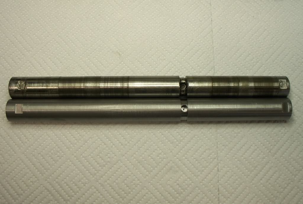
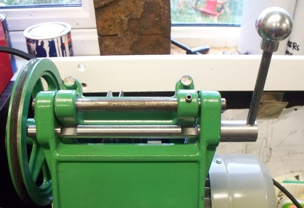
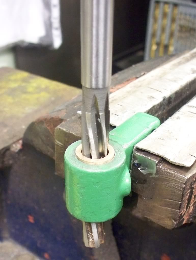
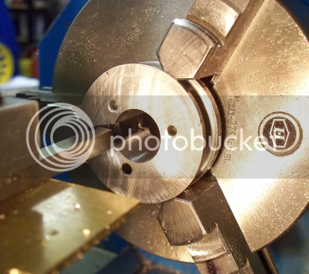
The main target to day was to complete the machining of the motor pulley and start rebuilding the Myford ML7 lathe. Boring of the 0.750” diameter hole proceeded with little drama if a little slowly. Once done to a nice snug fit, the next task was to cut the key way. Now I must admit that whilst I have read about the procedure in the past I have not had cause to cut one.

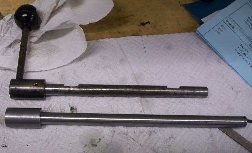
My starting point was to finds some tool steel of the same width as the key on the motor shaft, then grind the end of the tool steel to my own cutting profile. When done, I started by isolating the lathe from the power supply, to make sure I didn’t do anything silly! I placed the tools steel in the same position on the tool post as a boring bar but the cutting face on its side facing me.

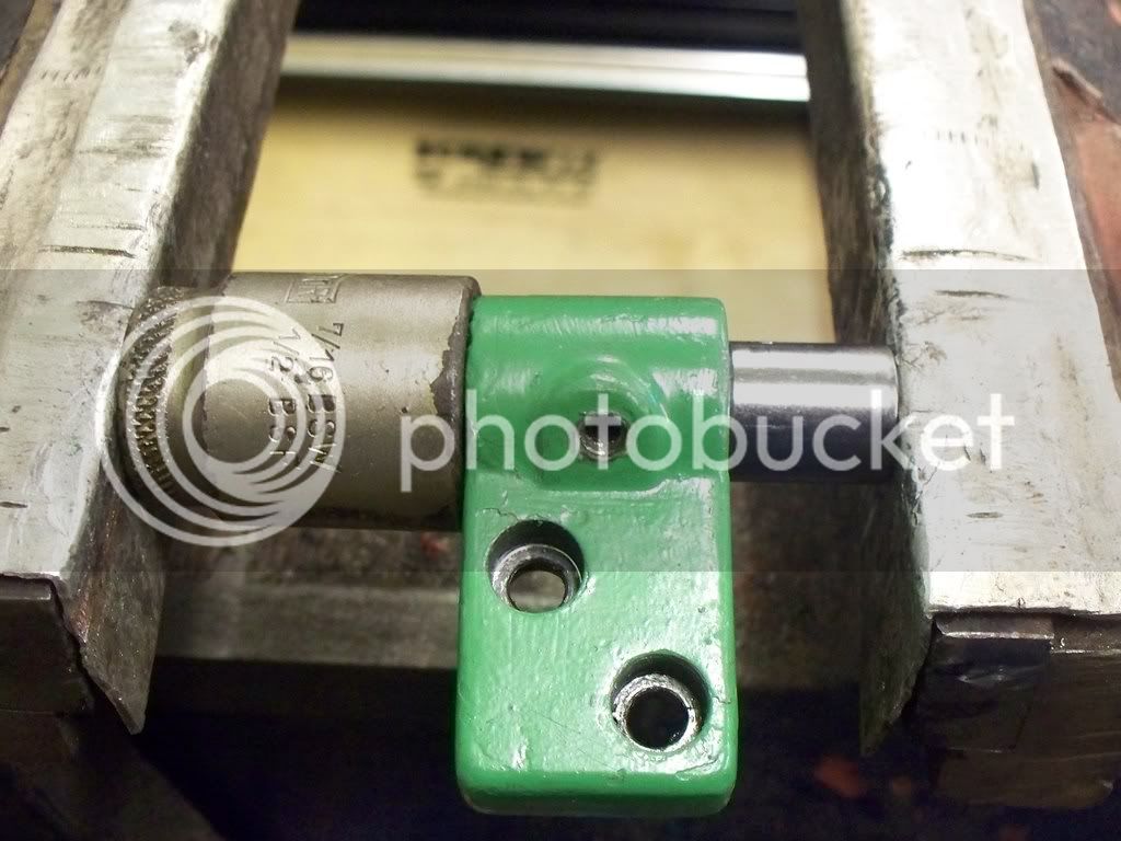
I thought it would be useful to make a mark on the pulley of where the key way was to be made and proceeded to make the first cut using the top slide. By only moving the cross slide out by 1 thou (0.001”)of an inch made another cut.

After a short time a nice keyway started to be formed but I was concerned as the amount of pressure being placed on the top slide. So I decided to use the cross slides main hand wheel instead, and keep the top slide closed. This certainly helped to speed up the process and felt a more comfortable a solution.

myfordrefurb28012009003.jpg


I will make a fixture for future use (add it to the ever growing list of tools to make!) which isolates the need to cross or top slide to be used. There are various examples in books and magazines and no doubt there will be many more keyways out there waiting to be made………

One silly mistake I made was to just cut the keyway where the pulley ended up when secured in the 3 jaw chuck. When trying the fit I was pleased, only then to find that the keyway position meant the grub screw used to secure the pulley was now partly over the pulley key! All I had to do was to take note BEFORE I made the keyway of where the tapped hole was. Not a great problem, but now I needed to drill and tap for a new grub screw.

myfordrefurb28012009008.jpg


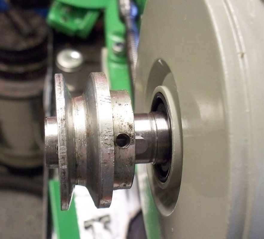
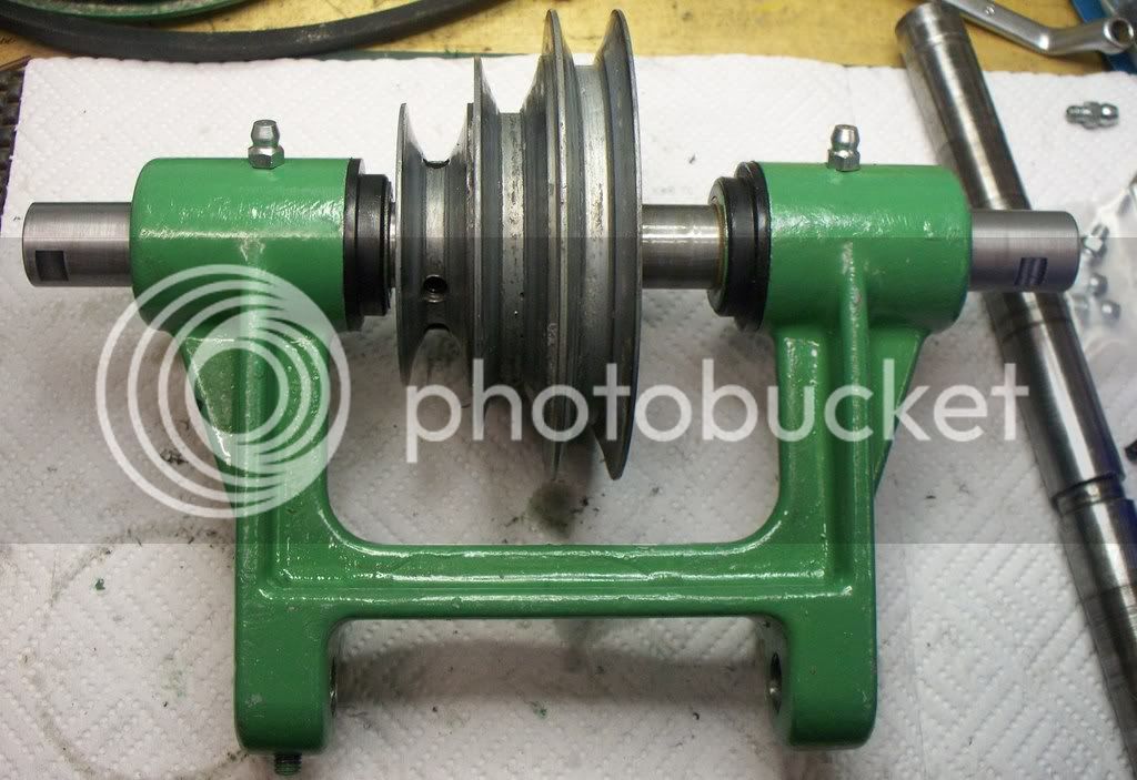
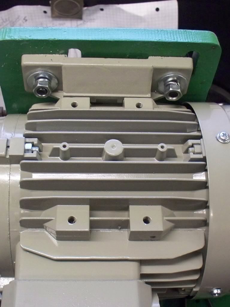
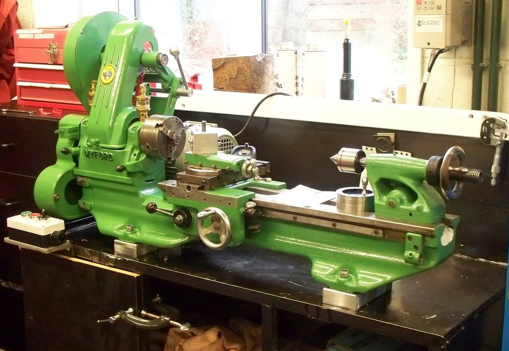
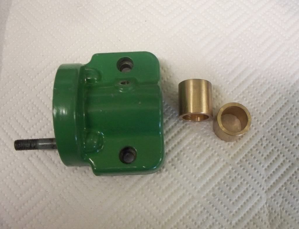
After the pulley was cleaned up a little it was provisionally fitted to the motor on its bracket. What next I asked myself? Well there were several boxes holding various screws, bolts and other fixtures so I though a general reorganization of parts would be useful. So I set up a table and sorted out all the parts of the great mechanical puzzle so I could see what was what to re-assemble the lathe.

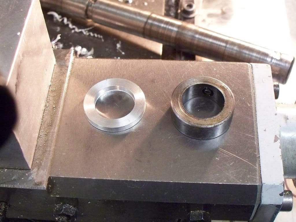
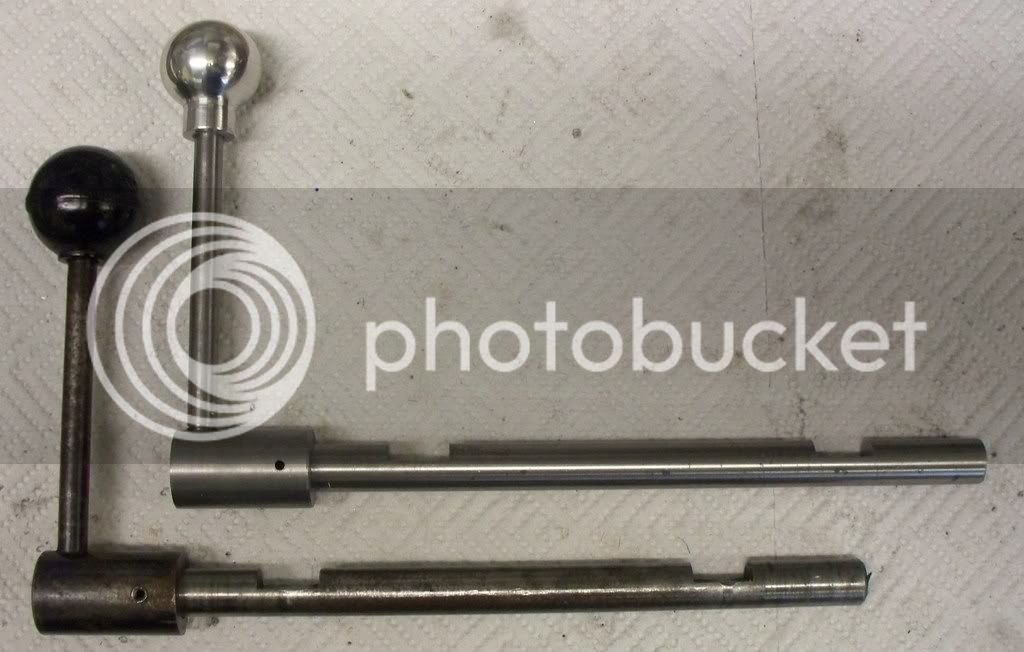
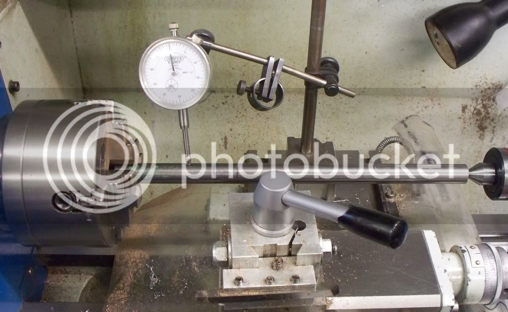
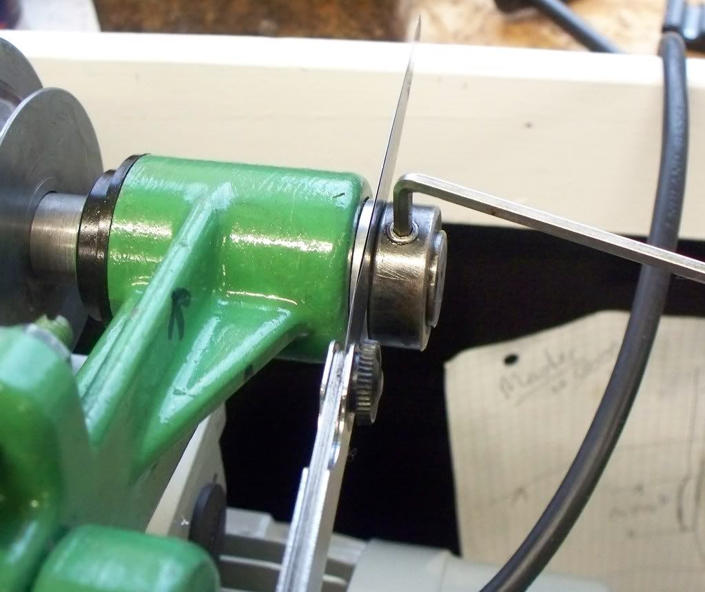
When the parts were sorted I thought the best way forward now was to put together as much as I could even if it had to come apart again when the parts from Myford arrive. A start was made by putting the tailstock back onto the lathe and it’s a part I think I will have to have another look at as it could be better. The next item assembled was the cross slide and saddle. The lead screw lock nuts were oiled up and the gib strip fitted. When looking at the cross slide I decided that since the fixings are metric (!) I would treat the lathe to new bolts. A new handle was fitted (not impressed with the handles sourced from a non Myford source) and I may have to make a small sleeve to match the difference between the handle bore and the saddle pin. Not a great difference and the handle tightens with the grub screw, but not really satisfactory. Another add it to the list item.

I have thought several times that the lathe has had work done on her before, and now I am certain. When I took the lathe apart I religiously kept everything in different small containers. Now putting the cross slide back together I couldn’t find any laminate shims that fit between the cross slide and two plates that fit under the top of the lathe bed and the base of the cross slide. There must have been something because the cross slide will not move if the securing bolts are fully tightened, and I remember it moving when the lathe arrived (or at least I think it did…)

So they will need to be purchased (that will be the third order!) and because of this omission I have decided that the lathe will be completely re-assembled and only then will I make the 3rd order from Myford. When the parts arrive the relevant parts will be disassembled and new ones fitted. So that’s what I will do.

So far the tailstock has been fitted along with the motor bracket and cross slide and saddle. The lead screw has also be partly fitted.

All in all not too bad a day for a change.
 
On the subject of the aluminum weld: If your vise was wide enough I'd think mounting the Al part between two pieces of brick would help with overheating the vise.
 
Mike, you're more than welcome to use it on your website so please go ahead.

Keep up the good work!

Peter
 
Took Peters advice and today I ordered a 1/2 length of the correct dimensioned threaded rod or 'leadscrew' form Kingston Engineering. I am now trying to track down some LB4 leaded bronze for the bushes so will let you know how I get on when it all arrives.....

Once again thanks Peter for the contact and I have quoted your response on my website. http://www.mikes-models.com/ccmyfordrefurb.html if you want to check an make sure its ok.

Mike
 
This morning started with a little apprehension and some careful machining. The countershaft was close to the outside diameter to fit the newly arrived last pair of oilite bushes. I was so close to the finish that a mistake would write off all the work done to date and the only steel bar I had of suitable size.

Well things went well and I managed to get a very nice fit when testing them on the countershaft casting. So I faced the ends to finished overall size.

Removing the shaft and feeling a little smug moved over to the bench to have a trial assembly. Imagine my disappointment then that whilst the shaft was a nice snug fit when put into one end only, it would not go through both.

Not wanting to damage the shaft I had a close look at the casting and was surprised that when looking at the set of bushes that the shaft was about to enter, there was about an 1/8th of an inch gap on one side! Removing the shaft I looked at the casting end on and one of the forks, or legs of the casting, was out by this 1/8th of an inch.
What to do? Well the first thought was to find a second hand replacement. Boring through both was quickly dismissed as not viable, so I thought since it would need replacing there would be no danger in trying to get them back in line.

Putting one leg securely in the vice, I gave the leg a gentle couple of ‘taps’ with a heavy peen hammer. Imagine my surprise when removing the casting to check it I found that both legs now seemed in line. A tentative trial of putting the new shaft through found that not only was it a good fit, it was a great fit! Using the correct Myford oil (bought on eBay) a few turns were made where no perceivable movement could be discerned and no tight spots felt. It was with even more apprehension that I then moved the bar back to the lathe to cut the groove using the parting tool. It was then over to the milling machine to cut the two shallow slots at each end.

My lathe seems to be of a different design to those that came later (mine was made in 1953) and the woodruff keys didn’t exist on my shaft. This was reinforced by the fact that no keyways were cut in the pulley or other fittings. So the new shaft replicated everything the old shaft had. This meant drilling a hole in the centre of the turned slot. You can see the comparison of new and old shafts in the photo depicting both old, and finished new shaft.

myfordrefurb31012009005.jpg


With the new shaft now finished and fitting well within the new bushes and countershaft casting, I decided to complete the counter shaft assembly. A start was made by trial fitting each component. The three pulley group was inspected and whilst a slacker fit on the shaft I decided to trial fit it to see how secure it would be. The two grub screws were removed and cleaned up and remembering to firstly fit the new rubber bushes, the shaft was put through the countershaft casting, through the pulley and out the other side. The hole on the slot was put uppermost and the smaller of the two grub screws (checked that it fitted earlier) was tightened. Then the larger screw was screwed in and the shaft seemed to be secured very well.

myfordrefurb31012009007.jpg


The only two remaining items to fit were the new 2BA oilers, but first I cleaned the threads out with a 2BA tap. That completed the bench based work and the whole assembly was taken over to the lathe and temporarily secured.

The next item to fit was the large pulley on the outside of the countershaft bracket, but first the new thrust washer was placed on the shaft between the pulley and the main casting. All that was left to do now was to secure the opposite end. This required a spacer to be made. I couldn’t find one so checked the photo’s of when it was taken apart and was surprised to find it didn’t have one. I could have removed the shaft and cut a further slot for the screw to bed down on, but thought it would be better to make a spacer.

myfordrefurb31012009008.jpg


When checking my bar stock I didn’t have any steel of the correct outside dimension. So I decided to make a temporary spacer from aluminum and order some steel to make a permanent one from. I don’t thing the aluminum is a long term solution. So having turned up the spacer, the end shaft stop was secured after setting the end float to 0.005” using feeler gauges (see photo).

myfordrefurb31012009009.jpg


Now the countershaft was in place I could see that the motor and its bracket will need some adjustment. A view further reinforced when trial fitting the new belt which seems awfully small to me (but the countershaft to headstock seems minute!) but it has yet to be set up.

Overall one of the better days work, certainly better than the last week or so!

You never know I may even get her ‘breathing’ tomorrow, using her new variable speed motor, and I am now much nearer the end than the beginning.
 
Mike,

Very nice :bow: looking forward to seeing it run.

Best Regards
Bob
 
Thanks Bob, it ran today.....sort off!

Today there was some success, some close calls regarding decision making and a little frustration at leaving the workshop before I wanted too.

First the close calls. When trial fitting the engine there didn’t seem to be much allowance on the travel the motor could make to allow the new drive belt to be fitted. On closer inspection the problem was the top electrical box on the new three phase electrical motor, which came into contact with the countershaft main bracket bolted to the back of the lathe.

To get the motor to fit in the required position my thoughts went from drilling new mounting holes in the motor base bracket, to making a new engine mounting system altogether. However when striping the whole system down and inspecting the new electric motor, there seemed to be tapings all around it. Since I thought I had been smart earlier when I turned the electrical connections box around, then why not move the position of the box again. There was the difficulty that the wires from the motor would have to be moved as well so that idea went straight out of the window!

Turning the motor around, the feet were only secured by two screws, and yes the positions of the other tapped holes all around the motor meant that the engine designers had built a very flexible mounting system. So in the end it was a simple case of unbolting the two feet and position them on another side, allowing the wiring box to be away from the back of the lathe.

01022009myfordrefurb006.jpg


Just imagine the difficulties I could have produced for myself if I had continued on one of the paths earlier! Now bolting the motor to the Myford motor base was simple and also in exactly the right position. Not only had that but the drive belt from the motor shaft to the countershaft fit perfectly. Reading the Myford manual the previous evening, one of the important set up items was to position the two connecting pulleys in line. To do this task a straight edge is all that is required.

01022009myfordrefurb001.jpg


The same procedure should be used to align the counter shaft pulleys with those on the headstock. And here I came across another supposed problem which yesterday I actually thought I had been clever and cured. The spacer I made for the right hand outside of the counter shaft wasn’t there when I dismantled the lathe for one simple reason, it’s not needed! To line up the two pulleys the spacer had to be moved because the countershaft pulley had to be moved over to the left (funny it was the same amount as the spacer eh!) and the outside large belt wheel takes up the movement required!

So after the necessary adjustments were made, and with the power off, I moved the motor pulley and since there didn’t seem to be any restrictions or tight spots, I threw the power switch and everything burst into life. I thought it would be useful to run the new bearings in a little and after using the Myford oiler via the two new oil nipples, the countershaft was allowed to run at varying speeds and change of direction. All seemed to be running smoothly and I can’t wait to turn some metal. The variable speed motor system is really excellent and I would say its nicer in its variation than the large Turner far Eastern lathe I have.

01022009myfordrefurb011.jpg


The next item to be made was the shaft that lies under the countershaft (see picture below) and I tried to remove the cotter that runs through the large part which holds the handle, with little success. SO I decided it would be quicker to make the complete assembly. After finding the BMS bar and cutting it to size I thought I would turn the whole shaft and handle, from one piece, but this would be a lot of lathe work. So the plan changed and the part will be made from three items, the main shaft, the handle and the boss that holds both the handle and shaft. The first part has been turned and the hole drilled to accept the shaft which only needs cutting to length, face the end and then mill the two slots.

01022009myfordrefurb012.jpg


All of which should be completed tomorrow.
 
Today I only managed to complete the lever that releases tension on the countershaft/headstock belt. It is surprising to me still on how much I underestimate time required for each task.

No real problems were encountered and I had a chance to use my tailstock die holder for the first time, and it was great. One problem I did encounter however was the size of the aluminum ball for the end of the shaft. My ball turning tool I built to make the chess set was too small for the size of ball I wanted to turn so a compromise size had to be made. However it will do the job and I can make a larger one if I want to later on when I make a Mk2 version.

myfordrefurb02022009006.jpg


When fitting the shaft everything fitted nicely so it was a job worth doing. The next stage will be to carry on with the rebuild.

myfordrefurb02022009007.jpg


Stop press: The leadscrew has just been delivered so tomorrow I will start on making the new leadscrew.
 
Not been to well this week, so the last couple of days have been sorting out some ‘odds and ends’ but surprisingly those odds and sods have seen quite a bit of the lathe come together and the long list of to do jobs, disappear.
The only large scale job left is the leadscrew and I am waiting for some reamers and other tooling to arrive before I can tackle that job.

The photo below shows the current state of play.

myfordrefurb07022009009.jpg


I did waste some time cursing a previous owner for the bracket made to hold the belt guard for the motor to countershaft. When fitted, the belt was off centre to the cover, but it was a simple case of the belt tensioning shaft being off and it should have been off centre! I only saw this after making a new bracket, then a spacer to put it exactly where the original bracket positioned it! Double Doh is an understatement.

Another silly waste of time was hunting down the bracing bracket between the motor base and countershaft casting. Where was it? Secured to the countershaft casting and just hanging loose! When putting the bracket to its position there was an obvious need to a spacer so I turned up a new one only to find the original on the table of spares later on! But that’s only to be expected when I am as dopey as I am at the moment.

Today I cleaned up and assembled the cross slide thread assembly and made a sheet steel shelf to attach to the splash back of the lathe stand. I wanted to bash a bit of metal and so I did, only making me worse that I was to start with……..so a week of unenforced errors really, no great drama’s just poor concentration and the little time I spent in the workshop, squandered. So it comes as a great surprise to see how much of the lathe has been completed.

Next week the reamers and other goodies will arrive and whilst I have had the cleaned (but hard used!)3 jaw chuck moving I may get to turn some bar on it by the end of the week! We will see as they say………..
 
Mike,

I hope your feeling better. It's amazing how you can't see the wood for the trees sometimes isn't it ???

Nice paint job. :bow:

Best Regards
Bob
 
Thanks for your support and interest Bob.

Todays progress update:-

myfordrefurb09022009andboringbar011.jpg


I have worked out why the last few days haven’t gone well ……….

Because I couldn’t progress the Myford refurbishment I thought I would return the Seal engine project. Since I needed to make a new inline boring bar to bore through the cylinder block casting that was the first job started today.

I thought it would be nice to use a part from the Myford for the boring bar. So the kn^&ck%d countershaft will be turned into an inline boring bar, so every time I use it I will remember the refurbishment. After turning the shaft down sufficiently to get rid of the wear and scoring, I removed it and took it over to the milling machine. I was about to drill two different diameter holes for tool steel, followed by two 5mm tapped hole for grub screws at 90° to them when SWMBO arrived with a large parcel.

So after unpacking the heavy parcel containing a new 4 jaw chuck for the Myford, and the necessary reamers for the bushes for the leadscrew, I could at last start on the only major part left to make for the Myford ML7, the leadscrew.

I put the boring bar idea to one side and removed the two leadscrew bearing castings from the lathe. Then I pressed out the old bushes using the’ old 2 socket method’ (see photo below).

myfordrefurb09022009andboringbar016.jpg


Both sets of old bearings came out easily, so the Colphos 90 was brought out of the stock room (aka the en-suite) so the 4 bushes required could be made. It became obvious quite early on however that I had made another error when buying the metal. My leaded bronze was big enough for the right hand side bearings, but was too small for the left hand, or gear side! I had assumed (wrongly) that the housings would have the same internal diameter, and of course they didn’t.

I then spent a horrendous amount of money ordering just 6” of 1” diameter Colphos, and will now have to wait until it arrives before I can complete the lathe work. Double Doh! It was one step forward and 1 and a ½ steps back!

It’s a good job I don’t employ myself, for if I did, I would have sacked myself!

After muttering under my breath for a while, I decide that I could at least go back to the inline boring bar, but then I thought that because the leadscrew project contains 5 or 6 different tasks, I could at least make a start on the right hand side of the leadscrew.

Decision made, the bronze bar was chucked and faced off. The keeping the minimum amount of bar out of the chuck I turned down the outside diameter of the new bushes using the half method and got the finished size to half a thou larger than the existing oilite bushes. The next task was to drill out and then ream the internal diameter. I used three progressively larger sizes of drills (after the centre drill) giving a hole slightly undersized, before using one of the new reamers to clean up the bush to the finished internal diameter.

When checking the dimensions of the old bushes I was surprised that the length of the two removed to find that they were different. So just in case I parted off both new bushes to the same length as the old ones.
Once they were cleaned up I pressed them back into the bracket casting before running the reamer through both just to make sure they went in square( which happily they did).

myfordrefurb09022009andboringbar022.jpg


And that was enough for today. Tomorrow I will take my life in my hands and turn down the left hand side of the new leadscrew to match the bearings and threaded end for the handle. After that I will be able to drill through the joining piece and ream to size before turning down the other end of the leadscrew.

Hopefully by the time I have finished all the tasks I can still do, the 1” diameter Colphos bronze will have arrived so in the end little time, if any will have been lost. Perhaps I will take myself back on again………you never know……watch this space.

So the answer to why things haven’t gone well in the past few days is simply really. I must have been frustrated more than I thought by waiting for the parts to arrive.
 
Hi Mike

Looking very nice indeed. Was the 4-jaw from RDG 6" Independant ??
Was looking to get one myself, non in stock Dec. last year, noted they're in now.

By the way, took the cracked cross slide to my mates the other night, shoo-ed the Yetis from his workshop.( I took him the cross slide to see if he could weld it, he wants one for a tool grinder he's making. NBG. )
So .. we attached a torque wrench to it via a 1" hex Allen key thing and gave a heave... it let go at about 38 ft/lbs.

There's not a lot of meat between the bottom of the tee-slots and the underside. He reckons someone has had something irregular bolted to it. Usually the slots let go first.

Anyway, he's got a bit of scrap cast to play with now :D

Dave
 
Hello Dave,

The chuck is a 150mm slim 4 Jaw with Myford thread and was from RDG £73.91 (+vat). It looks quite good so I'll let you know how I get on. I'll use the 4 jaw more than the 3 that came with it I expect.

That 38 ft/lbs doesn't seem much does it. (from my torque wrench days).

MM
 
MM
Following your posts with interest for I am doing a refurb on my ML7
although starting from the other end. So far I have fitted a new rack,
hand wheel pinion, saddle pinion and saddle bushes. Also modified all
gib adjuster screws to metric socket head makes adjusting much much
easier although the purists will frown.
My lathe seems to be of a
different design to those that came later (mine was made in 1953) and
the woodruff keys didn’t exist on my shaft
mine was made in the same year and is the same as yours.
Hope your health improves keep the posts coming they are of great interest.
BR

 
Metal Mickey, love the color and the job, looking forward to my next restore, don't know which one next, Atlas Shaper, SB lathe or drill press, this is what my mill looked like, we sure got away from gray by a long way, even had the handles chromed, I bet that is a sweet lathe to run, nice, Lathe Nut
Steinel-Mill.jpg
 
baldrocker said:
MM
Following your posts with interest for I am doing a refurb on my ML7
although starting from the other end. So far I have fitted a new rack,
hand wheel pinion, saddle pinion and saddle bushes. Also modified all
gib adjuster screws to metric socket head makes adjusting much much
easier although the purists will frown.
mine was made in the same year and is the same as yours.
Hope your health improves keep the posts coming they are of great interest.
BR

Hello BR, I think that if it works then that's the most important thing. I didn't think I would enjoy the refurbishment as much as I am doing. How about you?

lathe nut said:
Metal Mickey, love the color and the job, looking forward to my next restore, don't know which one next, Atlas Shaper, SB lathe or drill press, this is what my mill looked like, we sure got away from gray by a long way, even had the handles chromed, I bet that is a sweet lathe to run, nice, Lathe Nut
Steinel-Mill.jpg

Hello Lathe nut (great name!) I do like the green colour as well. I am not sure about their bright orange colour, have you seen that? Need sunglasses just to out into the workshop! You've done a nice job there. If your in the UK where did you get the chroming done and how much did it cost (if its not a rude question)?
 
I managed to get out into the workshop today, and spend the morning there. The two bushes for the left hand or gear end of the leadscrew were turned, bored and parted off to size with little drama.

myfordrefurb15022009001.jpg


When looking for material to make the shaft that fits the left hand side of the leadscrew, I could only find a piece that I had set aside for my boring bar! I will have to order some more stock for the boring bar as finishing the Myford refurbishment is my highest priority at the moment.

After setting the bar to run true in the four jaw chuck, with just enough showing to allow the DTI to sit on, it was faced off then centre drilled to allow the revolving centre to be used for turning. The 4 jaw was then opened enough to take the bar far enough out to turn the outside diameter to size over its length. With the live centre in place, the 4 jaw chuck was then tightened and set to run true again with the DTI.

myfordrefurb15022009002.jpg

(just double checking before cutting)

Once the shaft was running true I started to make the first cut but couldn't get the speed and feed to run without chatter. So I did the same as when turning the contra shaft, and ran the lathe very slowly at 90 rpm and the leadscrew at its finest setting. The length to be cut means that this is a slow job. Fortunately there isn't a lot to take off and I do get a good finish using this method.

Whilst the Turner lathe was doing its bit I spent some time tidying up some of the outstanding jobs on the Myford, such as replacing oil nipples and removing the belt tensioning shaft, so it can be drilled and a new roller pin fitted. I did take the opportunity to also clean the parts and then apply metal adhesive, so it won’t need to rely on the roller pin to take the strain.


The gears that came with the lathe were checked against the sizes for turning the leadscrew at its finest feed (0.0018 from memory) and sorted the gears out ready to attach when the leadscrew is complete. I seem to have some additional sizes, 2 x 80 teeth and a 127 tooth gear! I am however missing a 75 tooth gear so will have to seek one out.

The gear guide was placed into the gear cover and secured and one or two other small jobs done reducing the work left after the leadscrew shaft is completed. I am hoping to complete the complete refurbishment by the end of next week subject as always to health issues. It will be nice to get back to building the seal engine and I am looking forward to making the camshaft using Steve Huck’s method and cutting chart.

 
MM
Strange how the emphasis moves from making chuff chuffs to making tooling and
refurbishing machinery.
Having great fun working on the beast (just think how dull it would be to just
go out and buy a new one) although as I go further
more and more becomes apparent. Latest is a wobble in the countershaft pulley
makes the motor bounce up and down about 3/16" which in turn shakes
the whole lathe. Sourced a new pulley that needs to be bored to fit shaft,
difficult to do if some dodo has removed the original one. Must go back
and read your post from the start. Hows the health?
Regards
BR


Metal Mickey, Lathe Nut came easy when my wife called me that because I have several lathes, but I don't spend my money or time anywhere but work and home, after I get want she wants done and the yard work its in the shop I go, I live in the USA and got all the chrome on the machine done for one hundred dollars, it is a German built machine, great quality in it, its a Steniel, you machine is coming along nice, sure is a lot of fun getting them in shape to get the dirty, have fun, Lathe Nut
 

Latest posts

Back
Top