I had been working on these plans on and off for quite a long time, and now that I will have access to a very well equipped shop in the near future, I actually want to build it. I have read through many a threads here on the website and then realized I had a lot of problems with my design.
But here it is now, it's a 2 cylinder flathead engine using a 3/4" bore by 3/4" stroke. I designed it so that it would be quick and easy to machine, being that I will have limited time to use the shop. I will have access to very fast 4 axis CNC mills as well as CNC lathes, so I'm not too worried with some of the more complex shapes.
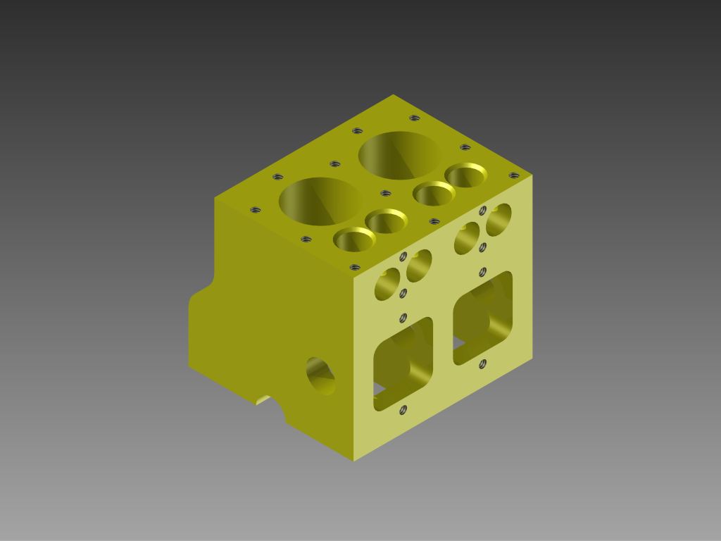
Engine Block. The valve chest is directly connected to the crankcase, and the camshaft will be lubricated by oil splashed from dippers on the bottom of the connecting rods. The intake/exhaust runners are 1/4".
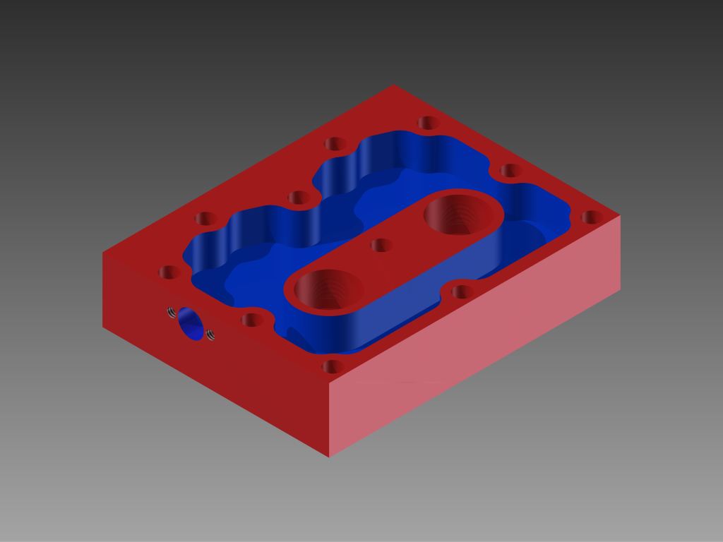
Top of the cylinder head. The blue area represents area that will have coolant flowing through it. I am relying heavily on the cooling in the head to also cool the block. To aid in this, I am planning on making the headgasket out of copper.
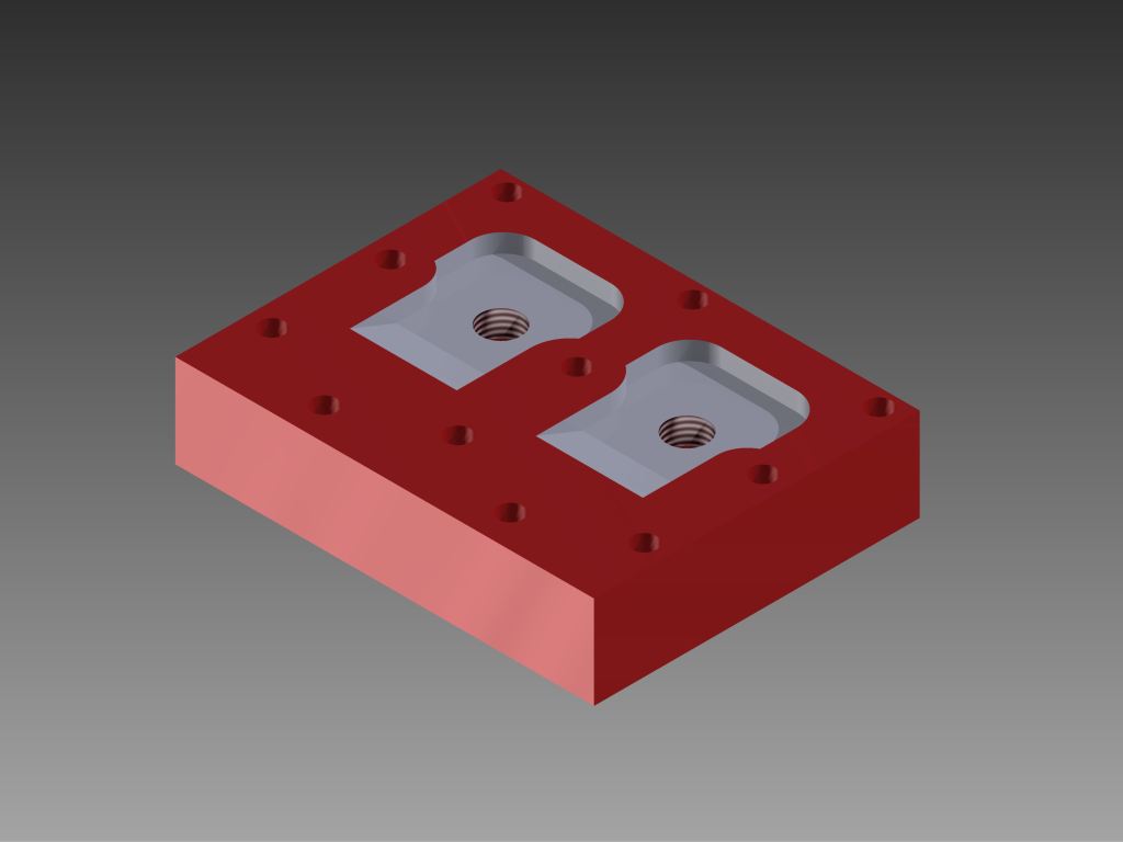
This is the bottom of the head, the white areas are the combustion chambers. Compression is near as makes no difference 7:1.
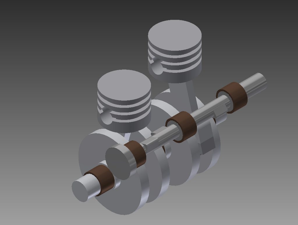
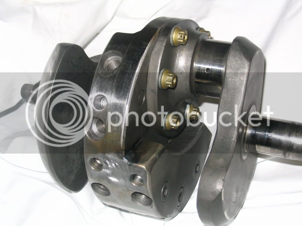
This is the rotating assembly. I am planning on using three piston rings, all made of PTFE (Teflon) which is good for 500F. The top two will be compression rings and the bottom will be the oil control ring. The wrist pin will be full floating, and will be retained by the piston rings. All the bearings are using standard Oilite bearings from McMaster Carr as well as the piston rings are standard PTFE Orings from McMaster.
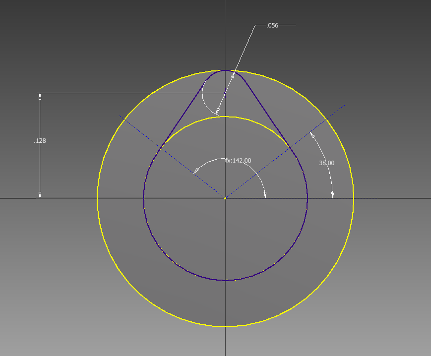
This is the profile of the cam. The intake/exhaust cam lobes have identical specs. There is a 112 degree lobe separation angle. The duration is 208 degrees, and the lift is .05625".
There is of course more to do. I am not sure if I want to integrate the other half of the main bearings into the oil pan or not yet. The water pump still needs to be designed. Many things need to be fine tuned yet, as well as the ignition system worked out, though that will be a fully electronic setup.
But here it is now, it's a 2 cylinder flathead engine using a 3/4" bore by 3/4" stroke. I designed it so that it would be quick and easy to machine, being that I will have limited time to use the shop. I will have access to very fast 4 axis CNC mills as well as CNC lathes, so I'm not too worried with some of the more complex shapes.
Engine Block. The valve chest is directly connected to the crankcase, and the camshaft will be lubricated by oil splashed from dippers on the bottom of the connecting rods. The intake/exhaust runners are 1/4".
Top of the cylinder head. The blue area represents area that will have coolant flowing through it. I am relying heavily on the cooling in the head to also cool the block. To aid in this, I am planning on making the headgasket out of copper.
This is the bottom of the head, the white areas are the combustion chambers. Compression is near as makes no difference 7:1.
This is the rotating assembly. I am planning on using three piston rings, all made of PTFE (Teflon) which is good for 500F. The top two will be compression rings and the bottom will be the oil control ring. The wrist pin will be full floating, and will be retained by the piston rings. All the bearings are using standard Oilite bearings from McMaster Carr as well as the piston rings are standard PTFE Orings from McMaster.
This is the profile of the cam. The intake/exhaust cam lobes have identical specs. There is a 112 degree lobe separation angle. The duration is 208 degrees, and the lift is .05625".
There is of course more to do. I am not sure if I want to integrate the other half of the main bearings into the oil pan or not yet. The water pump still needs to be designed. Many things need to be fine tuned yet, as well as the ignition system worked out, though that will be a fully electronic setup.