My Two Cylinder Design - Feedback welcome

Home Model Engine Machinist Forum

Help Support Home Model Engine Machinist Forum:

This site may earn a commission from merchant affiliate links, including eBay, Amazon, and others.

smpstech

Member
Joined
May 15, 2013
Messages
22
Reaction score
0
I had been working on these plans on and off for quite a long time, and now that I will have access to a very well equipped shop in the near future, I actually want to build it. I have read through many a threads here on the website and then realized I had a lot of problems with my design.

But here it is now, it's a 2 cylinder flathead engine using a 3/4" bore by 3/4" stroke. I designed it so that it would be quick and easy to machine, being that I will have limited time to use the shop. I will have access to very fast 4 axis CNC mills as well as CNC lathes, so I'm not too worried with some of the more complex shapes.
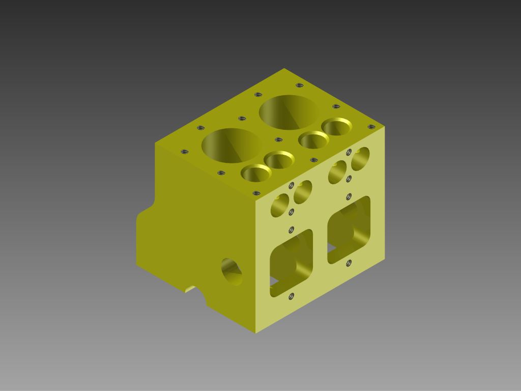
vgQXrYm.jpg


Engine Block. The valve chest is directly connected to the crankcase, and the camshaft will be lubricated by oil splashed from dippers on the bottom of the connecting rods. The intake/exhaust runners are 1/4".
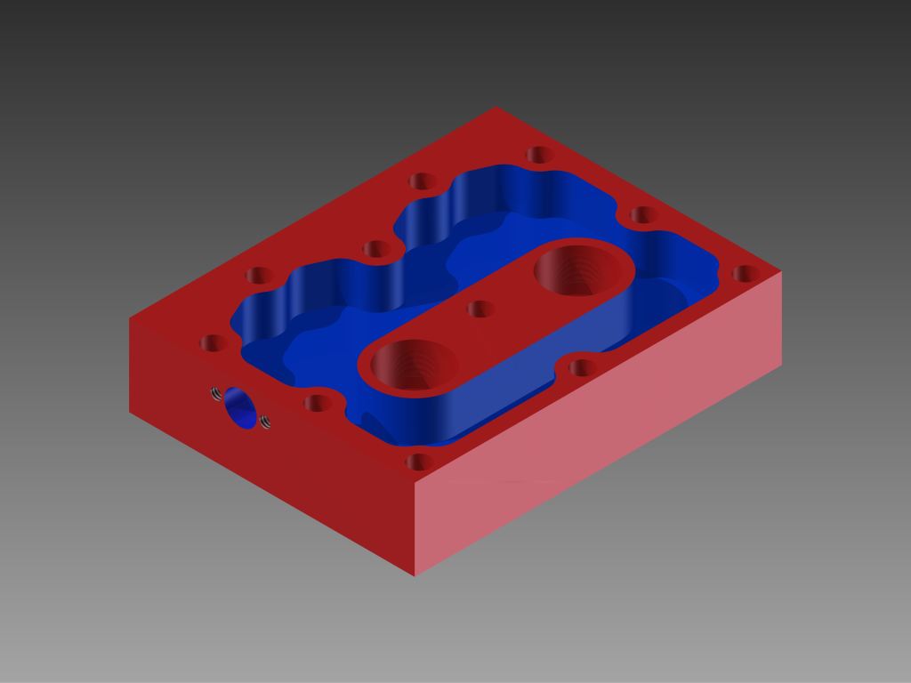
Z9G5yAZ.jpg


Top of the cylinder head. The blue area represents area that will have coolant flowing through it. I am relying heavily on the cooling in the head to also cool the block. To aid in this, I am planning on making the headgasket out of copper.
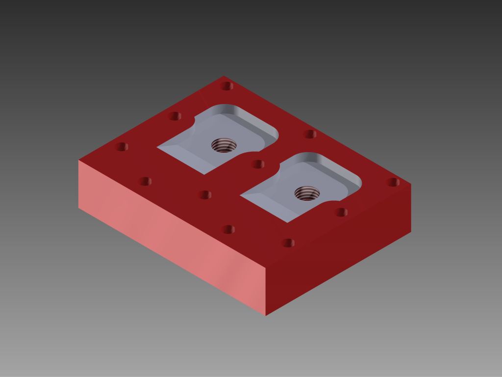
kSGdDSE.jpg


This is the bottom of the head, the white areas are the combustion chambers. Compression is near as makes no difference 7:1.
Pyvbt3dh.png


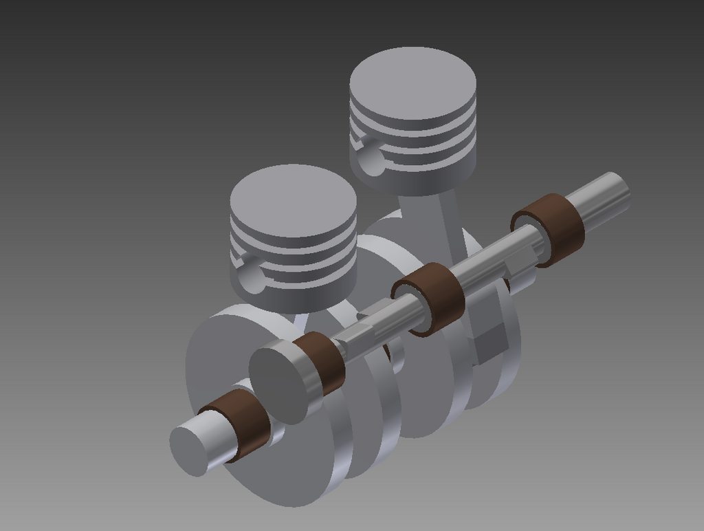
This is the rotating assembly. I am planning on using three piston rings, all made of PTFE (Teflon) which is good for 500F. The top two will be compression rings and the bottom will be the oil control ring. The wrist pin will be full floating, and will be retained by the piston rings. All the bearings are using standard Oilite bearings from McMaster Carr as well as the piston rings are standard PTFE Orings from McMaster.
WPL3dqM.png


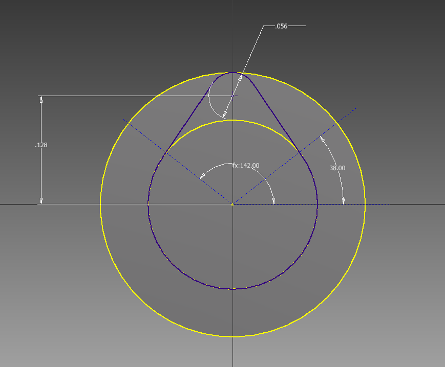
This is the profile of the cam. The intake/exhaust cam lobes have identical specs. There is a 112 degree lobe separation angle. The duration is 208 degrees, and the lift is .05625".

There is of course more to do. I am not sure if I want to integrate the other half of the main bearings into the oil pan or not yet. The water pump still needs to be designed. Many things need to be fine tuned yet, as well as the ignition system worked out, though that will be a fully electronic setup.
 
Like what you are doing, some suggestions. It appears that your crank throws are at 180 Degrees apart. To simplify the engine crankshaft manufacture and it may be easier to have a 360 Degree Crank as per the old British parallel twin motorcycles such as triumph Norton BSA etc . IE both pistons rise and fall together but fire 360 degrees apart .
I am not sure about PTFE for piston Rings. I have used it on gas compressors operating at 3600 psig ( 750hp ) but discharge gas temperature is limited to a Max of 150 Degree C and under API rules piston speed can not exceed 1000 Feet per minute.
PTFE has a very high co efficient of expansion and you will need a lot of end clearance and also allow for side clearance or those rings will jam in the ring groove of the piston and can do a lot of damage.
I would stick to good old cast iron for the piston ring and you may find that 1 ring per piston will more than likely be OK.
 
parallel twins usually have both cylinders at TDC at the same time, then there is always one cylinder firing on the down stroke, looks good, I am designing a parallet twin myself but it will be over head enclosed valve train.
 
This is looking to be a nice project. I'll follow this closely. Good luck with your project!
 
Hi,
I agree that you should go with the 360 degree crank, otherwise it will have a rather unusual lope. Is there a particular reason for not having a water jacket in the cylinder? Otherwise this sounds like an interesting engine haven't seen many L heads around lately other than the Wall 50 cc. I look forward to this build, and will be following it.
Art
 
Further Thoughts.
The Brit Twins ( apart from Matchless and AJS ) did not use a center main bearing on the crank.
The main bearings were either roller or ball bearings in most cases apart from the timing side bearing on the BSA Twins which was a bush and the achilles heel of that design.
These ball or roller bearings were lubricated by the oil mist and droplets that were present in the crankcase
If you use ball bearings they will allow for a bit of misalignment

Crank002.jpg
 
Interesting engine and I'm looking forward to your build. Maybe I missed it, but what material is the block made from?

I second the recommendation to go with cast iron rings and no more than two rings per cylinder. You could retain the piston pins with Teflon buttons.

Regards,

Chuck
 
I would also go for iron rings BUT only of its an iron block or you intend to sleeve what I suspect is an Ali block but your head design is not ideal for keeping a liner in place.

You may also want to look at your crank web shape as there is no counterbalance with the plain round profile if going with the 360deg option.

J
 
Further Thoughts.
The Brit Twins ( apart from Matchless and AJS ) did not use a center main bearing on the crank.
The main bearings were either roller or ball bearings in most cases apart from the timing side bearing on the BSA Twins which was a bush and the achilles heel of that design.
These ball or roller bearings were lubricated by the oil mist and droplets that were present in the crankcase
If you use ball bearings they will allow for a bit of misalignment

Goldstar, this is interesting. Where did you find this rendering?
 
Thanks for the feedback guys. These are the exact things I was worried about.

To answer a few questions:

I plan on making the block and head out of Cast Iron. All things considered, I will probably change the pistons to only use 1 Cast Iron piston ring, as what I've read has said that Cast Iron rings and Cast Iron cylinders go together well. The crankshaft, connecting rods, and piston will be aluminum.

I was weary of Cast Iron rings not because of the machining process but because of the heat treating. :hDe: But thinking about it I believe my college does have an oven capable of the temperatures needed in the material sciences lab.

And regarding the camshaft duration, I was basing those off of full size camshafts. But considering these little engines like to rev much higher than the full size counterparts, longer duration would make much more sense.
 
Just to get my 2 cents worth, I agree with everybody on cast iron rings, just to mention that I believe that Teflon when heated to much produces a toxic gas. Correct me if I'm wrong.
Jack
 
Hi:

Very nice.

Do you know if this can be made on a 3-D printer and if so how big would the printer need to be?

Thanks,

Terryt
 
I suppose it could, its only something like 2" by 2 1/2" by 2" big.

Just about any consumer 3D printer out there would be able to print it, like a Makerbot. Don't expect too much precision but it would be great for mocking things up.

I've actually toyed with the idea of getting a 3D printer and using it to do some sort of...lost plastic casting. Not sure if the plastic would have any sort of adverse effect on the metal being poured and it would probably melt much too slowly.
 
Right. Steel for the crank and 1144 makes a good crank.

You mentioned relying on the coolant in the cylinder head to cool the block. You might consider adding cylinder liners to the design which would let you cut out material from the block to make a water jacket around the upper one third of the cylinder liner. The cylinder walls probably need direct cooling more than the head needs it. The liners also give you a more forgiving design if you'd happen to make an error while machining the bores. A new liner can be made quickly compared to a new block.

You commented about Teflon giving off a dangerous gas if heated. If this comment is about using Teflon pads to hold the piston pins in place, cylinder temperature in the range of pin bore travel are probably not high enough to cause a problem. If this is a concern, you could use brass or aluminum pads to retain the piston pin.

I'm looking forward to seeing more of your design. Perhaps some sections through the porting in the block.

Regards,

Chuck
 
Looks to be a great little engine. Aluminium will be a bit soft for a crank.

I would have the crank pins 90° apart. It helps reduce a lot of the vibration of a 360° or 180° crank. These 2 animations explain it better.
Standard setup
xsstandard.gif


Rephased
xsrehase.gif


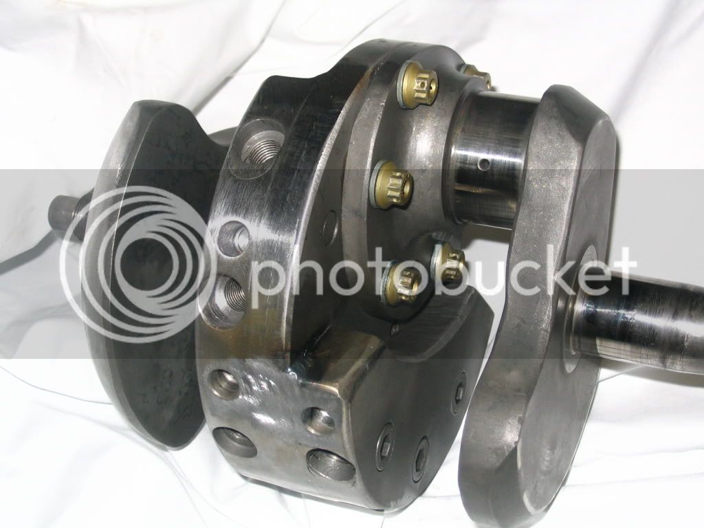
Bert Munro modified a brit twin by cutting the crank through the centre and twisting it 90° to give it better balance. I found a pic of a norton crank
bb095cbe.jpg

I know we are not building speed machine but it just helps to stop them bouncing off the table.
Just my 5 cents worth (I have run out of copper)

Brock
 
There is nothing wrong with a 180 deg. crank on a parallel twin. The Honda CB350 had one and nobody can argue that it was not good running machine. No doubt there were other motorcycles, that used that set-up, but I don't have personal knowledge of which ones did.

RWO
 
Back
Top