
You are using an out of date browser. It may not display this or other websites correctly.
You should upgrade or use an alternative browser.
You should upgrade or use an alternative browser.
My first engine...
- Thread starter arnoldb
- Start date


Help Support Home Model Engine Machinist Forum:
This site may earn a commission from merchant affiliate
links, including eBay, Amazon, and others.
arnoldb
Well-Known Member
- Joined
- Apr 8, 2009
- Messages
- 1,792
- Reaction score
- 12
Thanks Bob.
I know this is not the best way of lapping, but it is the best I could come up with for what I have available. ;D
Regards, Arnold
Not so far as I can establish. I make the lap long enough that the entire cylinder can be moved completely from one side to the other on it. With the lathe in high back-gear speed, and left hand on the clutch, I use my right hand to run the cylinder up and down the lap in side-to-side passes, and also allow it to rotate slowly while I do this. I can "feel" the tighter spots, so lap those slightly longer, until all feels even.Did you have any problems with taper using a wooden lap Huh? Huh?
I know this is not the best way of lapping, but it is the best I could come up with for what I have available. ;D
Regards, Arnold
arnoldb
Well-Known Member
- Joined
- Apr 8, 2009
- Messages
- 1,792
- Reaction score
- 12
I found some time to do more today :big:
Finished the valve block with it's steam passages - no real drama,but lot of careful cross-drilling. I have not yet started making up a set of drills with the cutting edges flattened for brass, so I had to be very careful, especially when joining up in angles") - first picture shows the completed block.
- first picture shows the completed block.
I have not yet practiced silver soldering, but with the knowledge gained from other threads here on HMEM (thanks guys :bow: ) I decided to give it a try. I filed a groove between the steam ports on the valve block on the face that needed to be soldered to the cylinder to make sure enough solder would wick get in there to "seal" the separate ports. Then thoroughly cleaned both surfaces, made and applied flux. I then tied the pieces together with binding wire to keep them in location and started heating the whole lot.
Here the drama started - my gas torch turned out to be too small for this job - I could not get the heat high enough, so I stopped & thought...
I have a portable butane/oxygen gas welding set as well - but the butane bottle was empty. I suddenly recalled the original owner telling me there was a fitting for the butane bottle to let it be (partly) refilled from a lighter-gas refill bottle. Found the adapter, so dashed to the convenience shop close by and bought a bottle of lighter gas. Refilled like a charm
So I set everything up again, with the gas torch positioned on a platform and playing heat on the whole lot. When I saw things were as hot as they were going to get, I fired up the portable gas set. By applying it's more direct heat along where I wanted the silver solder to go, it started to melt and wick in . It didn't turn out to be a very good job, but it worked, and I got things soldered - Picture 2 (UGLY!!!)
I then spent a good deal of time with water and Wet & Dry paper to clean thing up - a bit of work, but rewarding in it's own way. I had to re-lap both the cylinder and valve cylinder to get rid of the "nasty stuff" from the torching
I also made the piston and half of the piston rod - that was easy for a change!
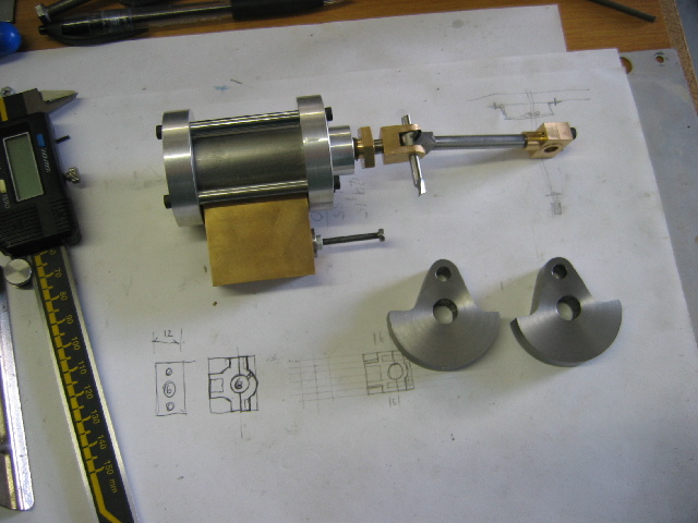
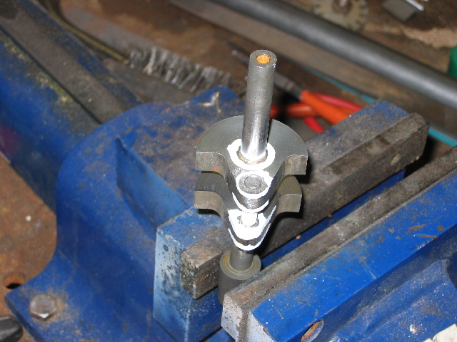
Picture 3 shows my progress so far with everything assembled - some light oil for the piston, and when I move it there is a VERY rewarding sound of air running through the steam passages woohoo1
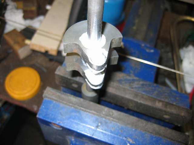
Pic 4 shows everything disassembled again. Sunday I have to do the chores - cleaning the house, ironing et al, and I have out-of town visitors coming over, so I'll have to play the good host. So most likely no further machining until next weekend; I can't wait to get the valve done to see if it will actually work ???


Finished the valve block with it's steam passages - no real drama,but lot of careful cross-drilling. I have not yet started making up a set of drills with the cutting edges flattened for brass, so I had to be very careful, especially when joining up in angles
- first picture shows the completed block.I have not yet practiced silver soldering, but with the knowledge gained from other threads here on HMEM (thanks guys :bow: ) I decided to give it a try. I filed a groove between the steam ports on the valve block on the face that needed to be soldered to the cylinder to make sure enough solder would wick get in there to "seal" the separate ports. Then thoroughly cleaned both surfaces, made and applied flux. I then tied the pieces together with binding wire to keep them in location and started heating the whole lot.
Here the drama started
- my gas torch turned out to be too small for this job - I could not get the heat high enough, so I stopped & thought...I have a portable butane/oxygen gas welding set as well - but the butane bottle was empty. I suddenly recalled the original owner telling me there was a fitting for the butane bottle to let it be (partly) refilled from a lighter-gas refill bottle. Found the adapter, so dashed to the convenience shop close by and bought a bottle of lighter gas. Refilled like a charm
So I set everything up again, with the gas torch positioned on a platform and playing heat on the whole lot. When I saw things were as hot as they were going to get, I fired up the portable gas set. By applying it's more direct heat along where I wanted the silver solder to go, it started to melt and wick in
. It didn't turn out to be a very good job, but it worked, and I got things soldered - Picture 2 (UGLY!!!)I then spent a good deal of time with water and Wet & Dry paper to clean thing up - a bit of work, but rewarding in it's own way. I had to re-lap both the cylinder and valve cylinder to get rid of the "nasty stuff" from the torching
I also made the piston and half of the piston rod - that was easy for a change!
Picture 3 shows my progress so far with everything assembled - some light oil for the piston, and when I move it there is a VERY rewarding sound of air running through the steam passages woohoo1
Pic 4 shows everything disassembled again. Sunday I have to do the chores - cleaning the house, ironing et al, and I have out-of town visitors coming over, so I'll have to play the good host. So most likely no further machining until next weekend; I can't wait to get the valve done to see if it will actually work ???
Greetings AB, Those pieces of engine are looking quite nice. Well done. I truly enjoy hearing about and seeing a man do such fine work with what materials and tooling one has at hand. Bravo! It is too bad that you had to begin again but then you at least were wise enough to realize anything else would have been a waste of time and material and did a re-group and continued to this point successfully. Tally Ho!
Cheers
BC1
Cheers
BC1
arnoldb
Well-Known Member
- Joined
- Apr 8, 2009
- Messages
- 1,792
- Reaction score
- 12
Well, got some more done today
Not much though, I finished the valve piston (on the second try ) - I have to post a new message in the "boo boo" section :-[ )
The first photo is of drilling the port-holes into the valve cylinder. Had a nice (for me) surprise there... I located the bottom of the vice jaw on center, and being lazy, I just decided that I'd take the reading on the vertical slide to locate the center of the piece. Diameter of the piece is 12 mm, so converted to thou's & turns (my Myford IS imperial...) turned down the vertical feed. Had a quick look and things were NOT right; I expected to visually see the center drill, well, on center, and it wasn't even close! Recalculated & relocated - same thing - th_wtf1 , but interesting.
So I measured the threads on the vertical slide, and this was the surprise for me - my vertical slide is metric - not imperial, as I expected. This is nice, as I'm a "metric heretic" ;D - which makes my life a lot easier!.
Well, proceeded to do things and basically finished the cross drilling. Some slots needed milling, so, knowing I cannot use the normal chuck in the headstock for milling ( Dont ask! :hDe: previous experience :-[ ), changed to the 4-jaw chuck. Proceeded to mill the one short slot; no problems. Turned the valve around, and started on the longer slot on the other side. My 4mm cutter decided it's NOT a fun-day, and walked right out of the 4-jaw, and pierced the slot on the other side... BOO-BOO (picture 2 - part in bottom) - ruined the piece.
So I started from scratch, and eventually finished the valve. Not pretty, but will do. My lathe's got a good amount of play on the headstock bearings, so milling of any kind is risky and produce erratic results. Picture 2 (top piece) shows the "usable" valve piston with these erratic results - horrible, isn't it?. Picture 3 shows the cylinder turned 180 degrees - at least that part of milling was better...
The valve piston works like a charm in the valve-block - I expected a lot less, the way it looks...
After the valve, I started on the piston rod cross/head link. That came out OK, but guess who has got some filing in his future to finish it - picture 4.
Lessons learned today...
1. Double-check feed screws on machines/tables...
2. Tough one... Don't over-tighten the 4-jaw, but don't under-tighten it either - better yet, get/make a collet chuck...
3. I need a milling machine :wall: :wall:
Regards, Arnold
PS, anybody noticed me using a toolbit as a spacer? - that cheapy threading bit shred her tip the first time I tried to use her - so only good for spacing now ;D
Ohh.. 'Nother lesson: Need parallels... need money!
Pics:


Not much though, I finished the valve piston (on the second try
) - I have to post a new message in the "boo boo" section :-[ )The first photo is of drilling the port-holes into the valve cylinder. Had a nice (for me) surprise there... I located the bottom of the vice jaw on center, and being lazy, I just decided that I'd take the reading on the vertical slide to locate the center of the piece. Diameter of the piece is 12 mm, so converted to thou's & turns (my Myford IS imperial...) turned down the vertical feed. Had a quick look and things were NOT right; I expected to visually see the center drill, well, on center, and it wasn't even close! Recalculated & relocated - same thing - th_wtf1 , but interesting.
So I measured the threads on the vertical slide, and this was the surprise for me - my vertical slide is metric - not imperial, as I expected. This is nice, as I'm a "metric heretic" ;D - which makes my life a lot easier!.
Well, proceeded to do things and basically finished the cross drilling. Some slots needed milling, so, knowing I cannot use the normal chuck in the headstock for milling ( Dont ask! :hDe: previous experience :-[ ), changed to the 4-jaw chuck. Proceeded to mill the one short slot; no problems. Turned the valve around, and started on the longer slot on the other side. My 4mm cutter decided it's NOT a fun-day, and walked right out of the 4-jaw, and pierced the slot on the other side... BOO-BOO (picture 2 - part in bottom) - ruined the piece.
So I started from scratch, and eventually finished the valve. Not pretty, but will do. My lathe's got a good amount of play on the headstock bearings, so milling of any kind is risky and produce erratic results. Picture 2 (top piece) shows the "usable" valve piston with these erratic results - horrible, isn't it?. Picture 3 shows the cylinder turned 180 degrees - at least that part of milling was better...
The valve piston works like a charm in the valve-block - I expected a lot less, the way it looks...
After the valve, I started on the piston rod cross/head link. That came out OK, but guess who has got some filing in his future to finish it
- picture 4.Lessons learned today...
1. Double-check feed screws on machines/tables...
2. Tough one... Don't over-tighten the 4-jaw, but don't under-tighten it either - better yet, get/make a collet chuck...
3. I need a milling machine :wall: :wall:
Regards, Arnold
PS, anybody noticed me using a toolbit as a spacer? - that cheapy threading bit shred her tip the first time I tried to use her - so only good for spacing now ;D
Ohh.. 'Nother lesson: Need parallels... need money!
Pics:
arnoldb
Well-Known Member
- Joined
- Apr 8, 2009
- Messages
- 1,792
- Reaction score
- 12
Been a long time since I posted anything; now I'm back to annoy everyone
Shop-time has been scarce, so progress is a bit slow; I have leave for the rest of this week, so shop time might be more
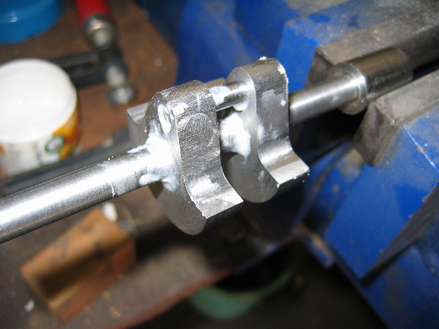
At least I got around to finishing the cross-head links, connecting rod and crankshaft webs.
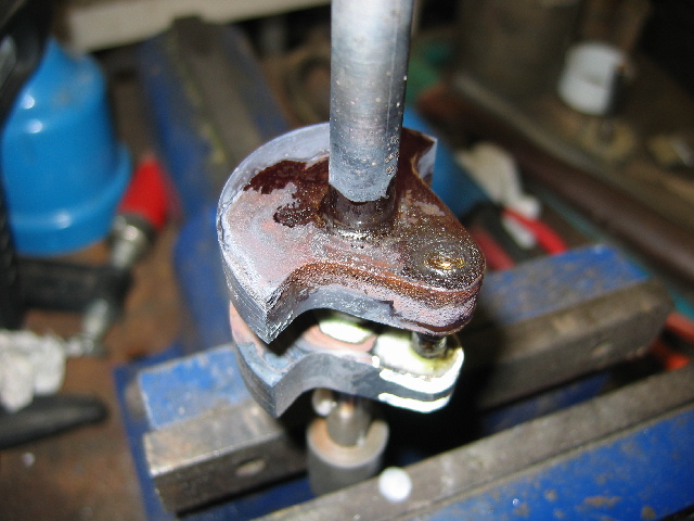
A close-up of the big-end bearing "thingy" ;D - When I look at it it looks good to me, but my camera speaks too much truth on macro mode
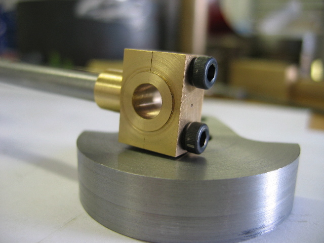
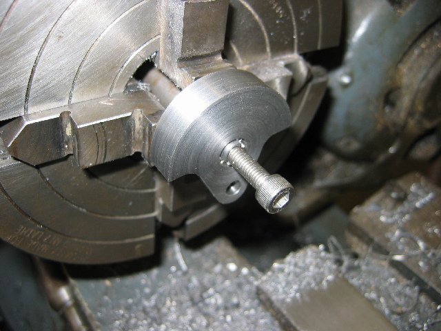
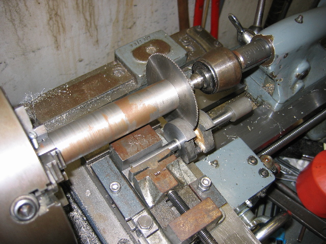
I machined the crank webs as a single piece from a very BIG (50mm) bolt I had available, and then used the bandsaw to cut it in half to get the 2 webs. The cut sides then needed facing, which I did on a quickly-made expanding arbor. For the arbor, I just turned a scrap piece of HRS down to size with a nice shoulder, then drilled for a 6mm thread, and tapped using the 1st & second taps, and only a couple of threads in with the final tap. This left a nice tapered thread. A quick trip to the bandsaw to split part-way length-wise, and "Maryak's your uncle" to quote another member of the forum Next photo shows one of the webs on the arbor after facing.
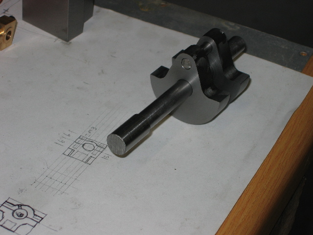
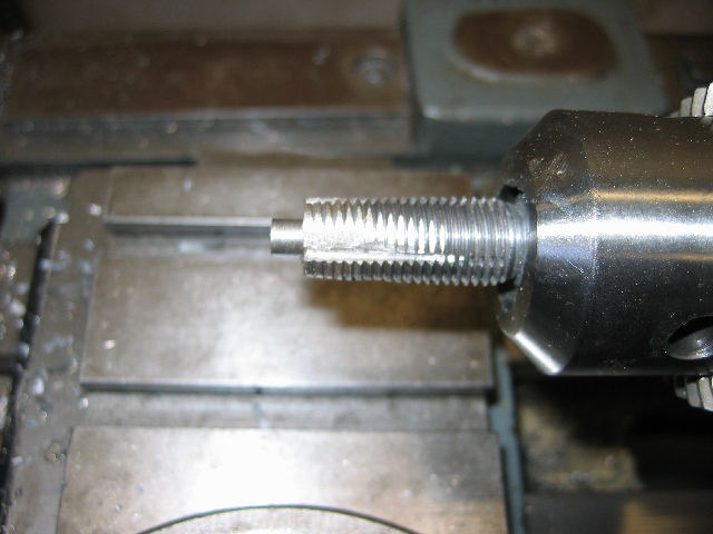
This morning I finished the main shaft for the crank - assembled for silver soldering:
Things were going too well - after my earlier experience with silver-soldering, I know I need my oxy-propane set, but the propane bottle is empty. Went to the local gas supplier to get it refilled, and they said "Sorry sir, we cannot refill those bottles anymore - we don't have the fittings for them" :wall: - that is the same company that sold & distributed them!
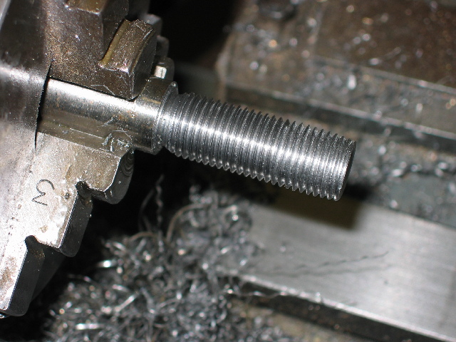
My only option is to fit the LPG regulator to one of my "camping" gas bottles (I have a lot of those). Problem is, I could not find any adapters to do this, so some more work is needed to make an adapter. I have a couple of "jet-cleaner" adapters that you take the jet out of the gas stove/light, screw into the cleaner, and onto the bottle. The jet is reversed, and when you open the bottle, the jet is "cleaned" if it was clogged. I can modify one of those to work as an adapter, but I need a 14x1.5mm tap for that. Nobody in Windhoek stocks it... "Special Order" only. Well, I spent some time (well, this entire afternoon) to single-point turn the beginings of tap out of silver steel; it should last for a one-time threading into brass without being hardened. Tomorrow, I'll mill & grind it to make cutting edges.
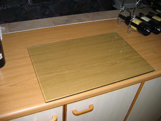
One of the items I started needing a lot was a marking-out platform, so I also splurged on a thick piece of 400x600x12mm glass today for just that purpose:
Regards, Arnold
Shop-time has been scarce, so progress is a bit slow; I have leave for the rest of this week, so shop time might be more
At least I got around to finishing the cross-head links, connecting rod and crankshaft webs.
A close-up of the big-end bearing "thingy" ;D - When I look at it it looks good to me, but my camera speaks too much truth on macro mode
I machined the crank webs as a single piece from a very BIG (50mm) bolt I had available, and then used the bandsaw to cut it in half to get the 2 webs. The cut sides then needed facing, which I did on a quickly-made expanding arbor. For the arbor, I just turned a scrap piece of HRS down to size with a nice shoulder, then drilled for a 6mm thread, and tapped using the 1st & second taps, and only a couple of threads in with the final tap. This left a nice tapered thread. A quick trip to the bandsaw to split part-way length-wise, and "Maryak's your uncle" to quote another member of the forum
Next photo shows one of the webs on the arbor after facing.
This morning I finished the main shaft for the crank - assembled for silver soldering:
Things were going too well - after my earlier experience with silver-soldering, I know I need my oxy-propane set, but the propane bottle is empty. Went to the local gas supplier to get it refilled, and they said "Sorry sir, we cannot refill those bottles anymore - we don't have the fittings for them" :wall: - that is the same company that sold & distributed them!
My only option is to fit the LPG regulator to one of my "camping" gas bottles (I have a lot of those). Problem is, I could not find any adapters to do this, so some more work is needed to make an adapter. I have a couple of "jet-cleaner" adapters that you take the jet out of the gas stove/light, screw into the cleaner, and onto the bottle. The jet is reversed, and when you open the bottle, the jet is "cleaned" if it was clogged. I can modify one of those to work as an adapter, but I need a 14x1.5mm tap for that. Nobody in Windhoek stocks it... "Special Order" only. Well, I spent some time (well, this entire afternoon) to single-point turn the beginings of tap out of silver steel; it should last for a one-time threading into brass without being hardened. Tomorrow, I'll mill & grind it to make cutting edges.
One of the items I started needing a lot was a marking-out platform, so I also splurged on a thick piece of 400x600x12mm glass today for just that purpose:
Regards, Arnold
arnoldb
Well-Known Member
- Joined
- Apr 8, 2009
- Messages
- 1,792
- Reaction score
- 12
Arnold,
Very Nice work. bow down and thanks for the honourable mention.
Best Regards
Bob
Thanks Bob - I really appreciate the feedback.
Regards, Arnold
arnoldb
Well-Known Member
- Joined
- Apr 8, 2009
- Messages
- 1,792
- Reaction score
- 12
I proceeded to finish the tap for the gas bottle fitting this morning - instead of milling the flutes on the tap, I just took the dremel & a fibre cutting disk to it - came out OK.
Tried to tap the brass adapter after drilling & boring correct size hole in it, and the tap would just jam up on start-up, so just used the bench grinder to remove some more of the metal behind the cutting edges. After this, tapping went in OK, but that brass squealed like a pig getting slaughtered.
Pretty much the crudest home-made tap:
With my gas works sorted out, I could now get back to my engine. Time to solder up that crank. Fluxed & ready for heat:
My camera's batteries became flatteries at this point, so no further photos of the day's work.
Maybe that is fortunate - things didn't go according to plan, and sensitive forum members should be spared the sights (and sounds) of what happened.
I had silver solder on parts of the assembly where I didn't want it, and in a couple of places I didn't have any where it was needed.
Some enlightenment did come towards the end of my efforts, so I took things apart and cleaned up again. Tomorrow I'll have another go; I have a good feeling about that
For now - on to some of the good liquid produced in Scotland and some grub
[Edit/added] I went back to http://www.homemodelenginemachinist.com/index.php?topic=4903.0 and I can kick myself. I wish to humbly apologize to the members of this forum who contributed to that thread for getting nearly _everything_ wrong from the great advice you gave. :bow: Tomorrow I'll do it right!
arnoldb
Well-Known Member
- Joined
- Apr 8, 2009
- Messages
- 1,792
- Reaction score
- 12
Another Miserable day in Windhoek - Weather-wise that is. In the workshop things went much better.
I cleaned all the crank's parts, and made a new crank pin. Then made a couple of punch marks on the circumference of the main shaft roughly on the webs' center lines and slipped them on; they stayed put in their places. Gave the new crank pin the same treatment.
Then I set to work with the tippex marker to mask off some lines & circles - result shown below. Must have made a very big boo-boo; I've never used so much tippex in my life :big:
Started fluxing; made the flux paste a little thicker than on previous occasions, and it stayed nicely in place, even if upside down:
Yesterday I realised I don't need the assistance of the small propane torch I've been using to try and heat up the assembly; Just use the oxy/propane set at a good whack. Get the flame below the parts to be soldered, and move it around to heat things up to a nice red glow; the flux then goes clear and start to flow; a bit more heat, and a dab with the silver solder rod, and voila - I still used too much silver solder though ;D
First web soldered - still glowing red hot; the camera flash makes it look a lot colder than it is:
After this, I just turned the whole assembly upside-down, added some more flux to the rest of the joints, heated & soldered. I got MUCH less of the oxidization I had than when I used the other torch to help heat up the assembly, so overall I'm happy.
I then proceeded to clean up the main shafts and web outsides - the silver-steel crank pin hardened up a lot with all the heating, so made for some interesting times on the web facings; a file still takes material off it easily, so it's not too hard&brittle - actually a good side-effect.
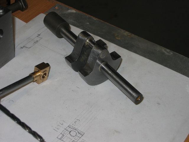
I then used my slitting saw to remove the main shaft part from between the webs:
Then I decided I must show some grit for a change, so I filed & sanded & sanded ;D
So this is where the crank is at tonight - not perfect, but it will do for me for now:
And a special THANKS GUYS to Paul, tel and gbritnell for the silver-soldering tips!
Regards, Arnold
I cleaned all the crank's parts, and made a new crank pin. Then made a couple of punch marks on the circumference of the main shaft roughly on the webs' center lines and slipped them on; they stayed put in their places. Gave the new crank pin the same treatment.
Then I set to work with the tippex marker to mask off some lines & circles - result shown below. Must have made a very big boo-boo; I've never used so much tippex in my life :big:
Started fluxing; made the flux paste a little thicker than on previous occasions, and it stayed nicely in place, even if upside down:
Yesterday I realised I don't need the assistance of the small propane torch I've been using to try and heat up the assembly; Just use the oxy/propane set at a good whack. Get the flame below the parts to be soldered, and move it around to heat things up to a nice red glow; the flux then goes clear and start to flow; a bit more heat, and a dab with the silver solder rod, and voila - I still used too much silver solder though ;D
First web soldered - still glowing red hot; the camera flash makes it look a lot colder than it is:
After this, I just turned the whole assembly upside-down, added some more flux to the rest of the joints, heated & soldered. I got MUCH less of the oxidization I had than when I used the other torch to help heat up the assembly, so overall I'm happy.
I then proceeded to clean up the main shafts and web outsides - the silver-steel crank pin hardened up a lot with all the heating, so made for some interesting times on the web facings; a file still takes material off it easily, so it's not too hard&brittle - actually a good side-effect.
I then used my slitting saw to remove the main shaft part from between the webs:
Then I decided I must show some grit for a change, so I filed & sanded & sanded ;D
So this is where the crank is at tonight - not perfect, but it will do for me for now:
And a special THANKS GUYS to Paul, tel and gbritnell for the silver-soldering tips!
Regards, Arnold
R
RobWilson
Guest
Great work arnold really like the look of that crank Thm:
Rob
Rob
Ah there is nothing like having a good crank (snicker) Great looking job you did there Arnold, I can't wait to see the engine when finished. Say, that conrod bearing looks suspiciously like the one that disappeared on me, how'd it get there? :big:
arnoldb
Well-Known Member
- Joined
- Apr 8, 2009
- Messages
- 1,792
- Reaction score
- 12
Thanks Very much BC1 - and neither can I!bearcar1 said:Great looking job you did there Arnold, I can't wait to see the engine when finished.
Rof} - at least I have one good one now :big:bearcar1 said:Ah there is nothing like having a good crank (snicker)
Hmm... "Postal Service" ? - and they went and outdone themselves on the value-add; they lumped it up in an excess block of brass & I had to dig it out! :big: :big:bearcar1 said:Say, that conrod bearing looks suspiciously like the one that disappeared on me, how'd it get there? :big:
Kind Regards, Arnold
Similar threads
- Replies
- 27
- Views
- 3K