my attempt to make the steam engine from oldboatguys plans

Home Model Engine Machinist Forum

Help Support Home Model Engine Machinist Forum:

This site may earn a commission from merchant affiliate links, including eBay, Amazon, and others.
Ariz

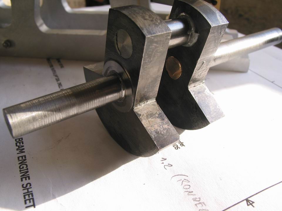
I've never silver soldered titanium, however it should work. Couple of comments based on my own experience. When you assembled the crank shaft before soldering were the bores and shafts clean? No oil or dirt allowed. Was there a little bit of clearance between the parts there has to be a space for the solder to wick (flow) into? An interference fit will not generally work. Was there a thin film of flux on the inside of the bores of the crank pieces and the shafts them selves? Without flux the parts will oxidize and the solder will not flow.

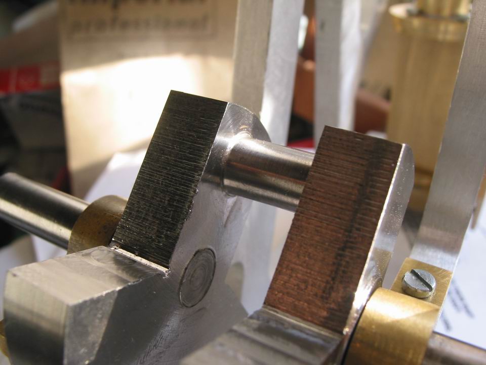
Myself I probably would have drilled a small hole slightly greater in diameter than the solder wire in each of the crank webs, like I was going to use a pin to hold the parts together. Then flux the bores and shafts. After assembling the parts I would put a small pieces of silver solder in the holes I'd drilled then heat.

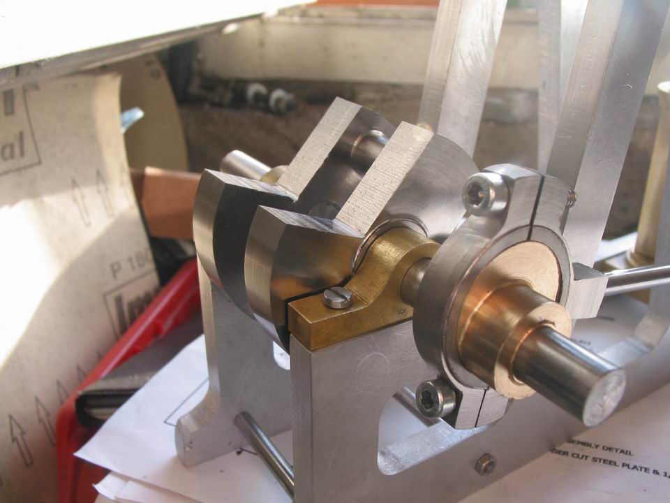
It looks like you did managed to get a decent crankshaft in the end. Looks good. Keep at it. :)

Regards

Ernie J
 
Hi Shopguy
well...

When you assembled the crank shaft before soldering were the bores and shafts clean?
sure, they were

Was there a little bit of clearance between the parts there has to be a space for the solder to wick (flow) into? An interference fit will not generally work.
not much clearance, it was a sort of interference fit

Was there a thin film of flux on the inside of the bores of the crank pieces and the shafts them selves?
no, being an interference fit the flux cannot reach the inside of the bore

so, I now know were I mistook the solder process :'(
I'll remember your suggestion (a small hole where to insert the silver wire) for the next time
and obviously I hope to not repeat these errors :)

thank you very much!

 
Ariz

Glad to help. Keep up the good work.

Ernie J
 
Ariz,
Depending on the titanium you use it will react with atmosphere above 500 degrees F. I don't know if that means silver solder will work or not. I have only ever welded that and uses an inert chamber or a back gas attachment on a TIG torch.
Good luck,
Sean
 
Ariz,

Just a thought, but X drilling and pins is another option. The pins can be locktited into position or the ends of the X drilled holes counter sunk and the pins riveted.

Hope this helps ???

Best Regards
Bob
 
thank you Maryak, Seanol, Shopguy

well, perhaps the option suggested by Maryak is what I can do without problems

but I tried another session of silver soldering this afternoon (before to read your advices)
don't know if it worked or not, tomorrow I'll examine the piece
if also this attempt goes wrong, I'll drill and pins the parts for sure

thank you again
 
I'm ostinate and I tried to solder those pieces many times without success! :mad:

then they were in such a condition that were useless

partic3.jpg


so, I made another crankshaft, always of steel shaft and titanium counterweight
this time I made the inner shaft in the way that I have learned here, so this part (2 counterweights and inner shaft) is a single piece of titanium
I turned between centers without any jig, simply a couple of holes at the correct distance

partic4.jpg


partic2.jpg


I retained the main shaft of steel, because I was sorry to waste so much titanium :)
instead to solder it, I used epoxy adhesive, may be that I'll add a pair of pins

What do you mean Maryak for X drill?


added other parts too, here is a test of the steam chest (without the square piston and the cover) and the leverage, it's ok

partic1.jpg


I'm at 90% now, the only missing parts are the crankshaft connecting rod (to the beam) and the flywheel

if I was less ostinate the engine would be finished now :big:


Ariz,

Could you please explain the reason for using titanium for the crankwebs.

The reason I ask, is that the machined counterweights are there for a reason, and not just to look nice. Unlike in an ic engine, where sometimes specialist materials are required, normal materials are perfectly adequate to take the stresses on this small engine.

The heavier materials used for the webs help to balance the weight of the conrod and piston to reduce vibration and stress on the reciprocating parts.

By using a lightweight material like titanium rather than say steel or cast iron, you are most probably upsetting the balance of the engine, and inducing more stress and vibration into it.

Titanium has a use in all sorts of applications, but I don't think so in the uses you are putting it to.


Blogs
 
ariz said:
What do you mean Maryak for X drill?

Ariz,

My apologies an X looks like a cross so X drilling is shorthand, (an abbreviation), for CROSS DRILLING or drilling through the diameter of a part.

I should know better, my wife is Russian and so I'm most times aware that English is not everyone's first language. :-[ :-[

Best Regards
Bob
 
Blogwitch, I agree with you, titanium is a bit lightweight for this type of use

the only reason because I used it was that it was the only material readly available in my shed
I have many pieces of 'automatic' steel, but of smaller diameter...

so, I thinked (or better, I hoped) that the engine could work anyway
maybe that I'm wrong

Maryak, thank you for your answer, I had supposed that but I wanted to be sure

 
well, the engine is almost finished: the only missing part is the flywheel

but I have sold my X2 mini-mill on ebay a few days ago, so I can't make the flywheel until I will buy a new milling machine...

so, I post the results of my work... the engine runs on compressed air, but it needs a lot of pressure (20 - 30 psi)

I think that it is due to the many leverages between the beam and the piston rod
I remember that on the Brian Rupnow engine that I made, the engine didn't run with the horizontal piston rod guide mounted
here there are so many pieces connected each other that the engine doesn't run easily
but it runs :)

the pics and the movies are not of the best quality
I explained why in another post

obg2.jpg


obg3.jpg


obg5.jpg


<embed src="http://www.cauzzi.it/ftp/MVI_0030.avi" autoplay="false" hidden="false" loop="false" type="application/mediaplayer" wmode="transparent" width="350" heigth="425"></embed>

<embed src="http://www.cauzzi.it/ftp/MVI_0034.avi" autoplay="false" hidden="false" loop="false" type="application/mediaplayer" wmode="transparent" width="350" heigth="425"></embed>


that's all
best regards
ariz
 
GREAT LOOKING ENGINE ariz :bow: :bow: :bow: :bow: :bow: Really nice work ;D
Regards Rob
 
Very nice job!!! I want to ear the "voice" :big: :big: :big:
Paolo
 
Ariz,

Great Looking Engine. :bow: :bow:

Best Regards
Bob
 
Sweet! I like it. Thm: Thm:
 
thank you very much... all of you

now I'll prepare my workshop for the new mill
I still haven't bought it, I think to do it in the next days

while I'm waiting, I'll clean the shed and the lathe
I wish to trim it too, any suggestion is welcome
 

Latest posts

Back
Top