Mounting a spin indexer on a small mill.

Home Model Engine Machinist Forum

Help Support Home Model Engine Machinist Forum:

This site may earn a commission from merchant affiliate links, including eBay, Amazon, and others.
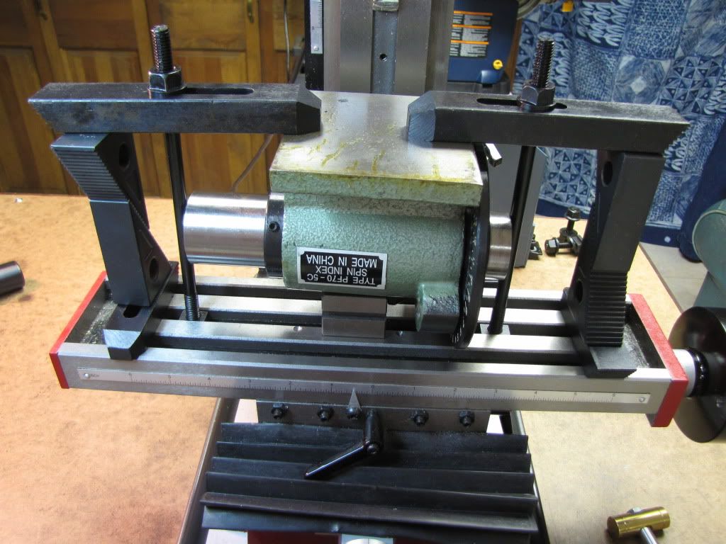
Zee, if you decide to go ahead with the key slot on the bottom, you might consider doing it in steps if you are not real confident in getting the alignment you are after.

Mill the slot in the spinner base (after you have aligned it as close as you can) at 1/4" wide or some dimension well under the slot size in your mill table. Then make a key with a stepped size that will fit both your mill table and spinner. If your alignment is satisfactory for you, you are done. If not, react the slot in the spinner a little larger (again after correcting the alignment) and make another key to fit. At some point, you will get exactly what you want.

You will find this a very valuable tool for future engine builds. I have a very expensive Hardinge indext head and a $29.00 spinner (eBay - made in Poland) & I use the spinner the most.

I'm keeping an eye on you. ;D ;D ;D
 
putputman said:
I'm keeping an eye on you. ;D ;D ;D

Goodie. Pressure is a good thing. :-\ I can certainly use more of that. ;D

Thanks Arv. I'm looking forward to using the spindex. As simple as it may be to most of you...I was one happy guy when I figured out how to set the DI on the carriage (thanks to several member's suggestions.).

I think I'm going to like this tool.

It's been said before...I'll say it again...great hobby...great forum...great members.
 
Still trying to get my head around this spindex...that is, how to mount it so I can modify it...

First goal is to make some slots so I can mount the thing on the mill table.
Second goal is to make the flange square so I can mount it in the vise.

First pic shows one possibility for making the slots. My question is...safe or unsafe? I can't mill both sides in one setting. The flange is too wide. It's do one side...remove, reclamp, then do the other. I can live with that.

IMG_0466.jpg


This pic was a go at mounting with the idea of milling the flange down square. I don't think so. Can't travel that far in Y.

IMG_0466.jpg


This pic shows another try. Pay no attention to the little triangles at the bottom...I would use shims instead. First...same question...safe or unsafe.

If safe...then any thoughts on how I can make this square? It's not about making the edge square to the bottom. Given a vise that is square to the table...putting the spindex in the vise...can it still be square?

IMG_0468.jpg


The 2nd goal is a nice to have. If necessary...I can see if there's anyone in the area who could do this for me.

But I need the slots. So the most important question is...will the first pic be okay?

Thanks.

I'm between weeding...hot and sweaty...hopefully this made sense. :big:
 
In any of your setups, can you get to the Spindex spindle to indicate it square?

Do you have an angle plate?
 
Hiya' Z'. In your first photo you are using a vee block under the body casting. I should point out that this is not a machined or 'indicated' part of the tool. To explain it in better terms, that surface is not parallel to the bottom of the casting or more importantly the spindle. THAT is where you should be indicating from so that the bottom of the casting can then be skimmed, and thus be flat, as well as in the same plane as the spindle center line, which is what you want to be striving towards. You should first indicate just the spindle to determine its accuracy. Use two, matched, vee blocks to do this, one supporting each end of just the bare spindle. Then, if it is acceptable, install the spindle in the base casting and again supporting the spindle at both ends, proceed to mill the bottom. Using only one vee block on the outside of the body casting is unstable and should be avoided. Some larger vee blocks would be the ticket as well as some support underneath the overhang of the base sides. The 'trick' here is to make the spindle the datum point and work your way out/up from there.


BC1
Jim
 
Hi Chip...yes I have an angle plate. See reply to Jim...

Hi Jim. Thanks. Yes, the vee block is there and no, I didn't think it would provide any kind of reference. Primarily because I don't believe the body of the spindex can be used as a reference. I was thinking, as you've suggested, that the spindle must be the reference (datum)...I'm just trying to figure out how. I had thought about putting a collet in with a piece of rod sticking out...but you seem to suggest it's just the spindle. Then I'm wondering if there's enough of it to indicate on?

I'm such a newbie at this...I'm assuming by spindle you mean the part that rotates inside the body. Only about 1" of it stick out.

I'm also assuming...perhaps wrongly...that the base is flat and square to the spindle. It shouldn't need skimming. The specs seem to indicate that but on the other hand...I saw (drat...can't remember his thread...) that 'one of the great members'...skimmed it and put a key in.

I don't doubt your point about making the spindle the datum point...still trying to figure out how.

Thanks. Not a big deal...I can slot the thing and move forward.

Seems like the clamping is okay from pic 1?
 
Hmm, awkward setup for a little mill.

You need to indicate the spindle to cut the sides of the flange square, and it's a long way down the side of the Spindex for a cutter to reach. That's why I asked ya about the slitting saw holder the other day, with a wider cutter you could at least establish a parallel line on the flange, so you'd have something to set up to after you flip the Spindex.

I don't like your clamping shown in the two copies of pic #1 for the same reasons already mentioned. Can't you get some V-blocks under that spindle, or some taller blocks ( a stack of step blocks? ) under the bottom side of the mounting flange?
Also, your left-hand clamp bugs me, with the stud closer to the wrong end of the strap. Fix it. ;D
 
Vernon said:
Hmm, awkward setup for a little mill.

That's why I asked ya about the slitting saw holder the other day, with a wider cutter you could at least establish a parallel line on the flange, so you'd have something to set up to after you flip the Spindex.

I don't like your clamping shown in the two copies of pic #1 for the same reasons already mentioned. Can't you get some V-blocks under that spindle, or some taller blocks ( a stack of step blocks? ) under the bottom side of the mounting flange?
Also, your left-hand clamp bugs me, with the stud closer to the wrong end of the strap. Fix it. ;D

Mm..methinks I have a few things WRONG! Well...good to know you think it's awkward. It's why I asked. It struck me that way too...I just don't know why yet.

As for the slitting saw holder...I saw the question but I don't understand it. Use a slitting saw to chop the flange down instead of a mill?

Ah...stud at wrong end of strap. Good to know. So the lesson is keep the stud as close to the work piece as possible. Thanks. I never made it to clamping school. :big:

Not sure I understand about v-block under spindle or more step blocks. A drawing would help a heap. My intent was to see if there's way anything to this idea or was I way off. I can certainly put another v-block under spindle and shim as necessary. I think that's what you're saying...

Add v-block or blocks under spindle end...move stud closer to work. Good to go?

Thanks. (Chip.)
 
Zee,

If you look at your opening post, where CC points you to my old article on modifying the spindex unit. The first four pictures show you how it has to be held for machining the foot.

Because your mill is so small, I don't think you could safely hold the spindex in your vise and have a rigid enough setup to do any accurate machining anyway.

The way to go is to clamp it to the table, and you will get as best a rigid setup as is possible with your machine.

Now you are only looking at the mounting slots for squaring up, whilst there are other areas where you can get it just as true, and by going this way, it will be a lot easier for you.

Before I go any further, remember that the clamping slots you want to make, don't have to be super accurate, they only need to be a slot that you can put a bolt thru and clamp the spindex to the table. One at the back, and one diagonally opposite at the front will be plenty strong enough. And they don't have to be machined in, an hacksaw and file will be plenty good enough if you can't hold it rigid enough to machine.

So now back to your problem of getting the spindex square to the table.

If you look at the attached C-o-C, it shows how, by just getting one edge machined square to the spindle, you can use the tables' edge to align it.

If you can get a setup, similar to my post, and get that one edge square, you will be laughing all the way to the bank. Once you have done that, only then, see if you can get mounting slots into the casting, as I don't know where in relation to the spindex casting your table slots line up to. But if the worst came to the worst, you can just use clamps, just as I do, they only take a couple of minutes to put on anyway.


Blogs

spindex.jpg
 
Blogs,

First off...my apologies...I had seen many of your other posts...it didn't occur to me you were the same person.

Secondly...thanks. I was fast coming to the same conclusion...get it clamped to the table. Accuracy of mounting slots is not critical.

Your tip about squaring to edge is good. However, it still leaves the question of getting the edge square to the spindle. But this may be left for a later time. Being able to put the spindex in the vise is only of convenience. I should be able to square the spindex to the table using the spindle...I'm hoping.

I'm thinking that getting the edge square to the spindle may be a bit much for my itty bitty mill. Ah well...it stays on the list for now.

Thanks very much.
 
Zee,

Not your fault, the people who know me realise it is me that is posting.

Now to get back to your problem. You are giving up too quickly. There are a lot of cat skinning ways, many not as obvious as others.

We need to come up with an easy solution for you to get that edge machined up.

I don't know how much reach your mill has in the quill department, and if you have enough room to get this done. But if it will work, you can't get a much easier setup than this.

Look at the attached drawing. By mounting the largest good quality straight bar into your spindex, and mounting it as shown, with the casting hanging over the edge of a t-slot or table edge, then clock along the bar to get the spindex square to the quill and straight to the table run. Clamp it all down tight.

Then come down with your cutter into the t-slot, and mill away at the edge of the casting. If you can get that done, it will be perfectly in line with the spindex spindle, so allowing you then to bolt a bar along the edge and then to be aligned against the table edge or if narrow enough, down into a t-slot, so that you can then clamp it down nice and square.

If you can't do it this way, it might be time for a bit of grovelling, to see if someone can machine that edge parallel to the spindle.

Blogs

machining.jpg


machining.jpg
 
Blogwitch said:
I don't know how much reach your mill has in the quill department, and if you have enough room to get this done.

Not enough. Body of spindex prevents mill head coming down enough for cutter to reach. And, while not a good idea, diameter of a chuck to hold cutter doesn't allow cutter reach flange from the side.

Blogwitch said:
If you can't do it this way, it might be time for a bit of grovelling, to see if someone can machine that edge parallel to the spindle.

I may take a trip to a nearby community college. Their curriculum lists what looks like a good machining program. I can also try a mech tech at work who happens to be a certified machinist (he doesn't work at it but maybe he knows someone).

No...not giving up. Just postponing. In the meantime I think I can clamp or make slots and use the tool.

Thanks Blogs. Your advice has been more helpful than you may know.
 
Zee,
As I recall, although it has been many years and I have CRS syndrome, I bolted a large piece of angle aluminum to the table.
Then I put in a large bar in the Spindex that stuck out both ends. With the Spindex turned on it's side, I set the bar on a 1-2-3 block on each end to make the bar parallel to the table. I may have had to put a parallel on top of each of the 1-2-3 blocks to get the edge of the Spindex nearest the table off the table. Then I clamped the Spindex to the angle aluminum with a few C-clamps, 1 near the table and two on top. Then milled the top edge. Once that edge is done, you can reverse it and either set it up on the 1-2-3 blocks again or use the just done edge to set it up. I used the 1-2-3 blocks and the same z setting on the mill so the two cleaned up edges would be equidistant to the spindle center line.

While it would be nice, the angle aluminum does not have to be a perfect right angle. Any mill stock will be close enough but it does need to be fairly good size.

Gail in NM
 
Thanks Gail,

So here's a pic...similar to 3rd pic earlier...

IMG_0469.jpg


It has a large bar (biggest I've got that fits) through the Spindex and on top of 1-2-3 blocks. My assumption is that should put the spindex parallel to the table.

Clamp on either side.

I don't have an angle bracket other than a small one...it doesn't fit anyway.

The little step block you see is there for illustration. I'm thinking shims but to keep them thin and in the middle. This to make the base (yet to be cleaned) perpendicular to table and therefore parallel to spindex. (Again...assuming that the base already is parallel to spindex.)

Then zip along the top.
Do as you suggest..flip it around to keep the same Z...and zip again.

Then figure out out to mount the thing upside down and put 4 slots in. They're not critical other than to make sure the thing is clamped down tight.

I'm sorry to be beating this to death...

Everyone's help is very much appreciated. I hope others are getting some value out of this.
 
Just a different slant on this forming in my old and dull grey matter ............ but ........... the requirement is to reduce the width of the Spindex base to suit the X2 and provide a couple of slots so it can be clamped to the mill table, accuracy is not super important as there will be enough clearance in the slots for adjustment to square it up .......... or have I missed something ???

CC
 
CrewCab said:
forming in my old and dull grey matter ...

At first I thought...ah...there I follow...but then I realized...same age...already there!
Wait...my matter is 'gray'...is there hope?

CrewCab said:
the requirement is to reduce the width of the Spindex base to suit the X2 and provide a couple of slots so it can be clamped to the mill table, accuracy is not super important as there will be enough clearance in the slots for adjustment to square it up .......... or have I missed something

That's exactly it. It seems the vise (yeah yeah...vice) is usually always mounted on the table. Milling the base to be square so it can be mounted in the vise would save time...but it's a nice to have.

There's no rush here...I may put the slots in so I can have some fun with the Spindex and then later get serious and 'improve it'.

Thanks CC.
 
Carl,
I think you are creeping up on it. On your set up, switch places with the clamp bolts and the 1-2-3 blocks to get the bolts closer to the Spindex. I know Vernon all ready beat you up on that, but it's important.

I don't remember how I put the slot in the base. It's been about 30 years since I did it. I just have one, but it is accurately parallel to the spindle. Although I have a larger milling machine now, I did it on a mill about the same size as yours.

I "think" that I used 4 spacers to support two stout bars in the x axis on the mill and clamped them down. Then I clamped the Spindex to the bottom of the bars along the edges using a couple of bolts as my Spindex has some clamp bolt holes in the edges. A few clamps would probably work for you as long as you take light cuts. I indicated the edge of the base in with a DTI so my slot would be in line with the spindle. Light cuts are the order of the day with a set up like this.

Gail in NM


Thanks Gail.

Yes I did wonder about the clamp bolts and the 1-2-3 blocks. (I knew Vernon was just waiting for an opportunity to beat me up again. He owes me beer you know.) I had it in my mind that it was more important that the blocks be up against the spindex so the bar would have good support. Probably not a problem with such a thick bar.

Thanks for the tips.
 
zeeprogrammer said:
There's no rush here...I may put the slots in so I can have some fun with the Spindex and then later get serious and 'improve it'.

So why not trim it to width and form a couple of slots with an angle grinder, tidy it up with a file and there you go, you can square it up before nipping it down. If, in the future, you find a suitable way to hold it or someone who can do it for you there should be plenty of meat left to square it up.

CC
 
zeeprogrammer said:
(I knew Vernon was just waiting for an opportunity to beat me up again. He owes me beer you know.)

Not "beer", "A beer"! It was a typo! :rant:

Besides, I wasn't beating you up over that, I just didn't want you to knock a Spindex on your foot. *beer* ;D


Latest posts

Back
Top