More supercharger questions

Home Model Engine Machinist Forum

Help Support Home Model Engine Machinist Forum:

This site may earn a commission from merchant affiliate links, including eBay, Amazon, and others.

nesikachad

Member
Joined
Oct 12, 2010
Messages
18
Reaction score
0
My education is limited to 12 grades. My math suffers as well but I've been able to BS my way through stuff for a long time now. There is math however that stops me dead in my tracks.

I'm reading on superchargers. Hypocycloids and Epicyloids are kicking my butt.

I have a Moki 2.1 cid front rotary valve 2S glow engine that I'd like to build into an FI engine. I'm going to machine my own roots style blower for it. This is for a speed plane that I have (RC air stuff)

Can/will anyone help me with the basic design requirements?

1. Rotor geometry
2. Rotor size

I'm just unsure how big/small to make this thing so that it will adequately feed the engine. My understanding is a 2S engine uses the same basic fundemental formula for dispacement as a 4S (bore*2)*stroke*.7853982.

My question is though since a good portion of the stroke is also used to empty/fill the cylinder isn't this formula a bit skewered? Shouldn't I just be using the volume of the cylinder where the piston is just about to break the seal on the exhaust port?
Once I have the #'s on this I can whip it up in CAD and machine it without much trouble. That's the "easy" part for me.

Thanks in advance.

Chad

 
Hi chadd

I'm sort of in the same boat as you as i started the super charging thread .

There has been some good reading because of it and iv sort of picked a few things up that will help with getting my engine running with out holeing to many pistons.

Even so i still have nothing to work with for displacement,rpm and type of blower to make. I do have some thing that can be made in Cad all iv really done for this is draw something that fits on top of my crank case.

So if you do come up with some thing id like to no about it. My motor is a 30cc what is yours how are you going to drive it up till now iv got 2 ideas one is turn the prop driver in to a toothed pulley or a dog that runs of the back of the crank pin like the OS91 charged 4 strokes.

here is the engine as it stands now 3 weeks in


DSCF0308.jpg
 
I've been able to locate an engineer with Eaton Superchargers. He wasn't in the office today, but will be tomorrow.

Don't know if he'll "play ball" with me on this, but hopefully so. If he does I'll certainly pass along what I find out. Nice job on your piece!

Is this an aircraft engine by chance?
 
Well that's good news lets hope he like the idea and give you some in put.

Yes mine is sort of a aircraft engine but it will never fly its all ready twice the wight of my DA50 that i have in a Edge 540 I'm just doing this to see if i can more than any thing.
 
Mr. Kaid from Eaton was pretty helful. So was Mr. Conley from Conley Precision miniatures.


Mr. Conley:

A supercharger/Forced Induction set up on a rotary valve piston port 2S engine won't work. Everything your trying to do gets pissed right out the exhaust port.

In order for it to work, it has to be modified significantly to resemble the Detroit two stroke diesel engine. This involves a cam driven poppet valve for the exhuast.

Mr. Kaid:

For simplicity sake, the conventional Roots style twin rotor supercharger is probably best. Using my Moki 210 as the example we guessed (literally) that displacement on the blower needs to be somewhere around 1.344 cid per rotation.

How this was derived:

I once had a Supercharged LS1 engine in a 2004 Pontiac GTO. The blower was a Magnuson 112 HH. The 112 blower is essentially about 1/3rd the displacement of the LS1 (354cid)

We used that as the benchmark and simply scrunched the numbers down to fit the Moki. The Moki displaces 2.1 cid. Because its a two stroke it fires every time vs. a 4S which obviously doesn't.

So, 1/3rd of 2.1 is .672cid multiply that times two and you get 1.344 for the blower's displacement. Divide that again by two and that's what we "think" each half of the blower needs to displace. From there its a pretty simple function to marry up a pair of rotors to generate that kind of volume. (gotta love CAD as it'll do the bulk of the work for you.)

Since the Moki peaks out around 10k rpm the blower RPM will be within tolerable limits. (the one in my car ran at over 14k at peak rpm/boost) Up to a certain point a blower can be overdriven but at some point one will quickly find diminishing returns. Horsepower just gets turned into heat and noise. . .

Sooo The question is can this be made to work. I know Mr. Conley is a brilliant man and has considerable experience. I'm just having a difficult time understanding how the engine won't benefit from added volume (which results in increased pressure) inside the crankcase. If its all going to piddle out the exhaust how the dern things run to begin with? And. . . how do they respond so well to modifications of crank port timing, exhaust port height/timing, and things like that? Ultimately aren't we attempting to do the same thing? (only in this case I'm basically "cheating" by using a pump instead of creative manipulation of things like stuffing the crankcase and radical port timing)

I think I'm going to pursue it just to be proven wrong. :)

Good thing SD has long winters. . .


C


There are plenty of turbocharged two strokes running around in snowmobiles and watercraft. What makes them work is the tuned pipe. Without a pipe any excess pressure will go right out the exhaust port. Without a pipe there is nothing to hold the charge in the cylinder. I'm sure improved scavenging will provide some power improvement at the cost of much greater fuel consumption.

So if you are already running a tuned pipe and still want more power go for it. If you don't have a pipe, that's the easiest way to improve the power output.
 
I do have a pipe for it. However one can never have too much powaaahhh! :bow: :bow:

I'm gonna build it. What the hell. It's a weekend project involving some computer work and whittling on scraps of 6061. Just gotta go find gears and bearings now.

Thanks.

C
 
Oh i know how to make a 2 stroke sing as i use to race bikes the down side is my engine is a 4 stroke and i all so broke the gear box on my lathe to day so im sort of on hold.

Chadd is you motor on glow fuel or petrol ?


As for 2 stroke's i love the smell of castrol r in the morning
 
K, here's what I gotz


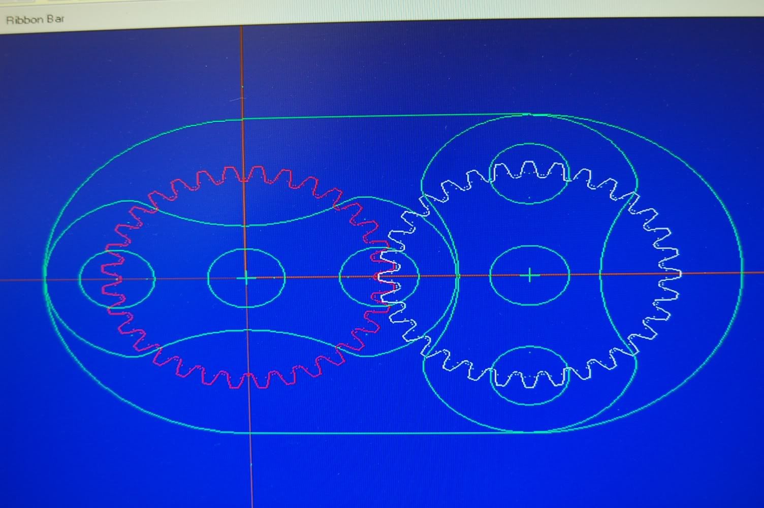
I literally copied an image off of Wikipedia showing the basic rotor geometry. Then I imported the rastor image into Mechanical Desktop and generated an IGES file from it. (call it an ultra ghetto optical comparator)


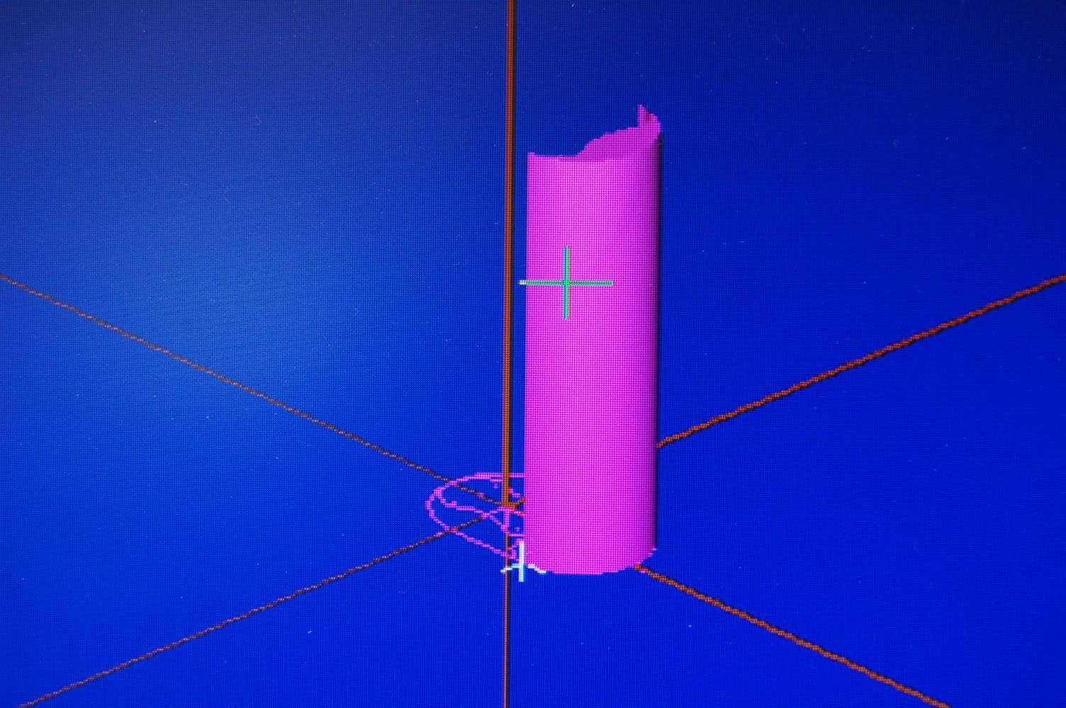
From there I brought it into my manufacturing software and started cleaning things up to ensure my arcs were all symmetrical. Then I drew an outside boundary to act as the inside of the blower case. The pink color is a solid model that I created to be able to figure out the volume. From there it was a combination of fiddlin with the scale and the length of the model to get the required hypothetical starting volume of .672 cid.

The depth of the cylinder (second photo) is 4.0" this will end up being the outside to outside length on the rotors.
The swept height (arc center) for the rotor is .925".

If this is indeed correct I've got a usable package size now to stuff inside this airplane. I'll probably increase the swept OD a bit and shorten the rotors some just to make a shorter package to give me some more room for mounting the thing to the motor.

I think I can make this work. . . ::)


DSC_0006-3.jpg


DSC_0007-3.jpg
 
Well this is about has close as iv got with mine. Its sort of based on a 1/4 scale V8 blower that i came across its been scaled down 50% iv all so got most of the mountings and fixing sort just need to sort out the gearing and what sort of rpm I'm going to spin it at.

One more thing I'm not to sure on is how close i should run the tips of the blower I'm at 0.19mm at the min but I'm working on the fact i can add some thing to the tips once i have made it all and seen how it runs something like a bit of nylon.

Please don't look to much in to the drawing its only a mock up and still needs work

View attachment charger in houseing.dwg
 

Latest posts

Back
Top