


What is sorely lacking here to fire once per 720 degrees is synchronization of the compression stroke. The ignition would need some way to know when an engine is on a compression stroke. One could use 3 Hall-effects, one for each rocker or push-rod and one on the crank. Then connect them to a 3 input 'AND' gate. This way when both rockers are at rest you know a compression stroke is about to happen and when the crank signal happens it fires the ignition. This setup however would mean adjusting the timing manually. One could also use the embedded magnet built into the flywheel for a crank signal. Or use the cam gear and crank flywheel. But in all reality wasted spark helps to keep the sparkplug clean and there are millions and millions of engines out there for years using it.
Side Note:
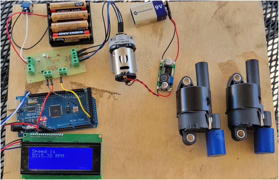
I have done a lot of testing of small engine ignitions and I can tell you right now that Walbro makes the worst. Ever hear of the Pulling-Poulan chainsaws and other Poulans? The reason they call them Pulling-Poulans which is now owned by Husqvarna and they now both use one type of Walbro ignition that is designed to reduce kick-back when starting. So you end up pulling and pulling to get the damn thing to start. What Walbro does is put everything into a single coil pack and it is considered a high voltage (@220Vac) CDI preprogrammed ignition. Now to be nice to the person trying to start one of these engines they retard the timing between 0 and 8 degrees ATDC. So it fires when the piston is going down already. I have 3 engines now that will either not start but make flames out the exhaust or they just slowly die. According to Walbro information it is very common on this type to retard timing 8 degrees ATDC and only start to increase timing once the engine reaches 450- 500 RPM which is nuts, it should be 200 RPM. Now I don't know the brand of ignition coil shown in the pictures but I suspect it's a Walbro. I've tried changing coil packs both OEM and even Chinese made ones with no luck. I've had some success increasing the gap between the coil and flywheel which increases timing but there was not enough adjustment. Increase the gap too much and I loose spark. The only thing I can think of is that when the flywheel is made there is core shift or something and the magnet is not positioned correctly, so need new flywheels.
Sorry I haven't been contributing much lately but business calls and prep for winter. I hope to get more done after Xmas.
Ray
Side Note:
I have done a lot of testing of small engine ignitions and I can tell you right now that Walbro makes the worst. Ever hear of the Pulling-Poulan chainsaws and other Poulans? The reason they call them Pulling-Poulans which is now owned by Husqvarna and they now both use one type of Walbro ignition that is designed to reduce kick-back when starting. So you end up pulling and pulling to get the damn thing to start. What Walbro does is put everything into a single coil pack and it is considered a high voltage (@220Vac) CDI preprogrammed ignition. Now to be nice to the person trying to start one of these engines they retard the timing between 0 and 8 degrees ATDC. So it fires when the piston is going down already. I have 3 engines now that will either not start but make flames out the exhaust or they just slowly die. According to Walbro information it is very common on this type to retard timing 8 degrees ATDC and only start to increase timing once the engine reaches 450- 500 RPM which is nuts, it should be 200 RPM. Now I don't know the brand of ignition coil shown in the pictures but I suspect it's a Walbro. I've tried changing coil packs both OEM and even Chinese made ones with no luck. I've had some success increasing the gap between the coil and flywheel which increases timing but there was not enough adjustment. Increase the gap too much and I loose spark. The only thing I can think of is that when the flywheel is made there is core shift or something and the magnet is not positioned correctly, so need new flywheels.
Sorry I haven't been contributing much lately but business calls and prep for winter. I hope to get more done after Xmas.
Ray

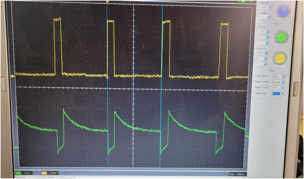
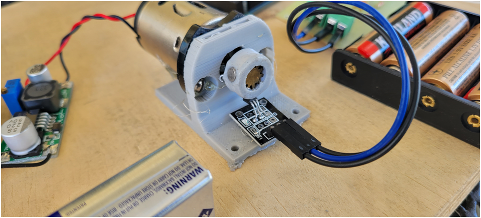

") The magnets are placed at 60 and 240 degrees, the 60 degrees of rotation should give the Nano enough time to do the calculations for 36 degrees of timing advance. Of course all of this depends on the strength of the magnet, Hall-Effect used, and the distance between them. As I show in the movie this setup of mine shows the on/off points have a 10 degree field of sweep, 55-65 & 235-245. This can be compensated for in the firmware code. And yes I know that the magnets are on the face of the flywheel instead of on the edge but, the motor is sitting vertical so the armature movement is very stable.
The magnets are placed at 60 and 240 degrees, the 60 degrees of rotation should give the Nano enough time to do the calculations for 36 degrees of timing advance. Of course all of this depends on the strength of the magnet, Hall-Effect used, and the distance between them. As I show in the movie this setup of mine shows the on/off points have a 10 degree field of sweep, 55-65 & 235-245. This can be compensated for in the firmware code. And yes I know that the magnets are on the face of the flywheel instead of on the edge but, the motor is sitting vertical so the armature movement is very stable.