ML Midge Build

Home Model Engine Machinist Forum

Help Support Home Model Engine Machinist Forum:

This site may earn a commission from merchant affiliate links, including eBay, Amazon, and others.
Hi Chris - I missed your post and just had a late reminder on email :rolleyes:.

Good to see them coming together, they are looking good so far.

Re the use of small taps - I agree it is always a bit heart in mouth with small taps but something you might like to see - it's a bit late now of course but in case you need it in the future....

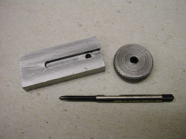
Grind a small flat on the side of the tap just above the thread - just long enough to take a grubscrew point. Then turn and knurl a small disc about 25mm dia and 6/7mm thick and drill for the tap. Cross drill for a small grubscrew and you have a very controllable tap wrench for small taps. 25mm dia is just right for 10,8 BA and 2/2.5mm or so. The motion is very 'circular' as opposed to the wringing action of a tee bar. Originally I supported the tap by very lightly closing the chuck jaws - literally just touching but have recently found it much better to drill a small piece of brass to take the tap shank (loose fit) and hold that in the chuck as a guide.

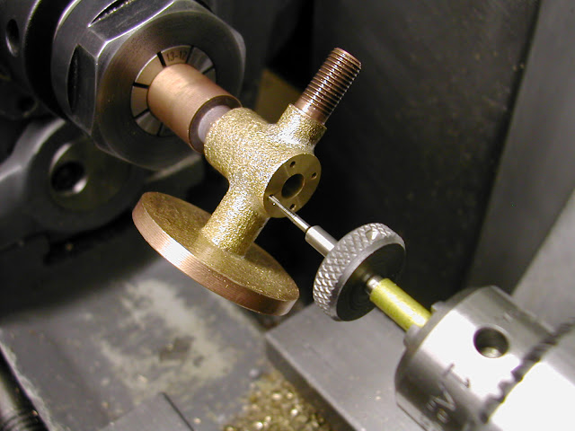
Here are a couple of pics from the Waller build - its being used on the lathe but the principle's the same. It's 12BA and a smaller diameter wrench- about 19mm.
DSCN4190.JPG


DSCN4175.JPG


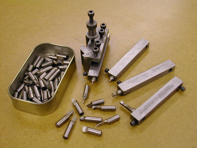
Having been down the route you show - there's even a couple of sprung loaded points to support the tap chuck now lying fairly redundant in the tray I can say this is much the better way, particularly for 'feel' as to whats happening with the tap.

Hope that's of use to you.

Not that much further to go now eh? Whats next to do?

regards - Ramon
 
Ramon,
Thanks for the tip. Meullernick posted a picture of a commercially made version of that tool and I did try to find one without any luck. I don't have knurling tool, but I will get one soon and will make something similar to your setup.

Next? Well I managed to get hold of some genuine 3/4" StressProof steel, so I will start on the crankshafts. I will also part off the pistons and drill/ream the wrist pin holes. I'm waiting for some diamond paste to arrive in the mail and I will buy one of these next week:

http://www.altronics.com.au/index.asp?area=item&id=X0111

Chris
 
I have the crankshafts about 80% completed. The shafts have been polished with 600 W&D on a metal ruler to be a nice sliding fit in the crankcase journals. I left the first one way oversize and it took forever to polish it to fit. The second one I turned down to about 6.04mm and started with 360 W&D. That was much quicker.

Today I made an offset jig and started turning the crank pin on one of the crankshafts. It was a nerve wracking experience. On two occasions the tool dug in, breaking the tip off the tool and dislodging the crankshaft. Luckily I had left plenty of 'meat' on the crankpin so I was able to reset the crank in the jig and machine out the gouge in the pin. I'm not sure why this is happening. I used a freshly sharpened HSS bit in my diamond tool holder and I was taking very light cuts.

One possible cause I can think of is that the jig isn't gripping the crank properly and the crank is shifting very slightly causing the dig-in. The reason for my suspicion is that when I made the jig I drilled the hole to 5.9mm and reamed it to 6mm. It seems my new 5.9mm drill bit wasn't very true because the reamer went thru too easily without taking off much metal at all. It basically pushed straight in for the first half of the depth. The crank seems to be tight in the jig, but who knows? I think I'll drill and tap the jig to take a cap screw to clamp the crankshaft. Currently it only relies on the chuck jaws for clamping.

Maybe a diamond tool holder isn't the best tool for this job either? It has a LOT of back rake on it and I wonder if this might be causing, or at least exacerbating, the dig-in. I've used it on dozens of jobs, but never with StressProof steel and never on a job as critical as this. Can anyone comment on this and/or recommend a more suitable tool grind for this job?

Chris

P.S. The pin is still oversize in the bottom photo. It will be turned to 3mm and polished to fit the conrod.

IMG_20130223_170307.jpg


machining crank pin.jpg
 
Last edited:
Hi Chris - I haven't used one but I would have thought your tangential tool holder would be okay though it might be a bit large for such a small item. The problem I would say definitely lies in the gripping power of your fixture. You could help matters considerably if you put a very small centre in the end of the crankpin and support it with a tailstock centre. - I usually make the pin overlong and turn the centre away after if required but a small centre left in won't hurt anything.

Regarding tooling have you thought of using FC3 cutter shanks for toolbits?
Held in a steel bar - 3/8 x 1/2 -they make super cutting tools and can be ground to all sorts of shapes......

0_0000Image0003.JPG


I find the best way to hold them for grinding is to drill a hole in the end of a short length of round bar as a handle and hold the bit with a grub screw.

I have recently posted this elsewhere - apologies for repeating myself.

I find that tough steel En24t and the like usually needs a fair degree of top and back rake - nice and sharp for the finishing cuts and a reasonable radius on the tip.

You are getting on with them - not long now. Working on the backplates on mine

Regards - Ramon
 
Thanks Ramon,
I'll put a small pip in the crank pin as you suggest. I have a couple of mm of extra length in the pin to machine off.

My collection of milling cutters is tiny, but I do have a few 100mm sticks of 6mm round HSS I bought for making small boring bars. I also have a set of the old Armstrong style tool holders that take 1/4" square tool bits. I have a left, right and straight holder. To date when I've needed to grind up a tool (like my fin cutting tool) I have used those. I have a good supply of 2 1/2 x 1/4" sticks of HSS.

I've been following your build on HEM. They are looking good!
 
Today I finished the crankshafts and I'm very happy with the results. I tried drilling a small centre in the pin, but the resulting 'pip' wasn't very true and my dead centre would not engage snugly in the pip. Not sure why this happened, but I decided to mill, drill and tap the offset jig for a SHCS. That greatly improved the gripping power of the jig and I was able to turn the second crankshaft without any slippages.

The crankpins were turned to 3.05mm then I used 600 and 800 W&D to remove the rest of the metal until the pin was a snug fit in a 3mm reamed hole in a piece of scrap ali. Next I will make the conrods and they should also be a snug fit on the pins.

One of the crankpins rubs on the backplate, so I will have to face the backplate slightly, which should be easy enough to do. I just need to determine from the plans what the gap between the crankpin and backplate is supposed to be. I suppose I could use a feeler gauge to measure the gap?

Chris

P1030975.jpg


P1030982.jpg


P1030983.jpg
 
I usually use a crankshaft jig like yours, but without the split. I clamp the work using the screw threads in the end of the crank intended for the propellor stud. I insert a screw through some washers and pull the thrust face of the crank hard against the face of the jig. In cases when the crank threads are male, I use a nut instead of a screw. I don't think I've ever had a slip. I use carbide inserts, nothing too special, but ground to a sharp edge , rather than honed.
 
Hi Chris - glad they worked out okay in the end - doesn't matter how you get there ;)

I use a different method than the fixture you and RK are using - more 'universal' but I like RKs idea of the bolt right through and I guess, RK, if the shaft has a threaded end you could use a hollow threaded 'nut' as a draw bar if the shaft doesnt protrude through far enough. The only con as far as I can see is that it's dedicated to the one shaft but of course if made large enough it could easilly have three/four holes at differing radii.

The other thing I would like to just say ref 'centering' the pin is that if there is a one in the end and you do happen to have it slip it can quickly be clocked in true again using a wobbler

Regards - Ramon
 
Thanks Ramon.

Both of the crankpins rub on their backplate. Upon checking my plans it turns out the metric version doesn't include any clearance, so at least I know my machining wasn't the problem. The original inch plans include 0.015" of clearance. I'm going to have to remount the backplates and machine off the excess. My options appear to be:

1. mount the backplate on some sort of expanding mandrel (which I will have to make) and face on the lathe, or
2. screw the backplate to a piece of square stock through the screw holes, mount in the mill vice and mill the excess off.

I would appreciate any advice.

P1030948.jpg
 
Hi Chris, there are a number of options open however the usual expanding mandrel won't be viable as you won't be able to expand it as the screw will be hidden by the backplate.

You could do as you say and screw it to a block and hold in the mill or indeed the chuck on the lathe or..

If you have soft jaws for your three jaw you could machine them to take the flange - that would be my favoured approach but not everyone has a set of soft jaws.

Or (second favoured option) you could turn a ring chuck from ali which is a good method for holding such parts...

Take a short piece of round bar about 12-15mm bigger in diameter than the flange on the BP and turn a step on about 1mm deep and 5mm long then part off about 2-3mm beyond the step.

Reverse in the chuck and drill/bore through to 2-3mm smaller diameter than the flange.

Turn a recess in to take the flange leaving .5mm to come off and then remove from the chuck and hacksaw through in one place.

Return to the chuck with the cut between two jaws and nip sufficiently tight enough to turn the recess to accept the flange.

Pop the flange in, tighten up and face off.

You can make it from anything - Ali, steel etc. and it shouldnt take much longer than describing it :)

Hope that helps - Ramon
 
Hi Chris, just remembered I had this pic which should give you an idea of what I mean....

DSCN2401.JPG

In this case the ring chuck is actually held in soft jaws but thats not essential - ordinary jaws are just fine.
By turning the first step as described it helps when locating the short length in the jaws - just push the step up to the jaws for good alignment

Ramon
 
Thanks for the photo Ramon. Now it's clear what you are suggesting. No soft jaws, so I'll make up a ring chuck like yours. I've never seen these before and I imagine they are useful for a variety of jobs. I continue to learn new techniques from this forum. Building an engine is a steep learning curve, but the techniques learned make it well worth the effort.
Chris
 
Hi Chris, glad that was of use.

Yes they are a good little 'get me by' and hold the work extremely well particularly if you want to face something off quite thin. Their limitation is the lack of repeatablity (of concentricity) once taken out of the chuck. Marking where the no1 jaw is can help in that direction but usually the only way to get absolute concentricity is to re use them for something larger and re bore to suit.

As you say the learning curve can be steep but all these things add up to make matters much easier in the coming projects ;).

Regards - Ramon
 
I made a ring chuck and it worked perfectly. Thanks Ramon. I now have the required clearance between the backplate and the crankpin. Thm:

My diamond paste arrived yesterday. I have a dozen syringes ranging from 325 grit up to 60,000 grit. I bought an ultrasonic cleaner which I hope to receive on Mon or Tue. It's lapping time!

adjusting backplate depth.jpg
 
Today I lapped my cylinder liners. I can't say I enjoyed the job. It was slow and messy.

I used diamond paste in grits of 325, 600, 800 and 1200. I cleaned the liners and the lap in the ultrasonic cleaner between grits. I ran the lap at 300 RPM in the lathe and tried to dwell on the area below the ports in an effort to make that portion slightly wider than the portion above the ports. Whether I actually achieved this is anyone's guess.

The finish looks pretty good. It's quite shiny. I hope I didn't polish it too much. I took about 20 photos, but this was the best I could do.

You can probably see that my transfer slots aren't perfectly centred on the liner resulting in a sloped channel. I thought I had this nailed, but I guess it's the limitation of the lathe milling attachment. Or maybe it's me. :D

P1040009.jpg
 
Wow Jack that's awsome lappingThm: great work
where did you get your diamond kit from, I can't find a supplier on this side of the globe :)
 

Latest posts

Back
Top