ML Midge Build

Home Model Engine Machinist Forum

Help Support Home Model Engine Machinist Forum:

This site may earn a commission from merchant affiliate links, including eBay, Amazon, and others.

jack620

Well-Known Member
Joined
Jan 6, 2013
Messages
322
Reaction score
113
Location
Melbourne, Australia
Ladies and Gents. I thought it would be a good idea to have one thread for my ML Midge build rather than start a new thread for every part. I am building two Midges from a set of metric plans supplied by Ron Chernich.

So far I have completed the outside machining of the crankcases, the heads are finished and the cylinder liners have been machined. The last pic shows what I've done so far.

The boring of the crankcases is waiting until I receive a 10mm ER40 collet to grip the "nose" of the crankcase.

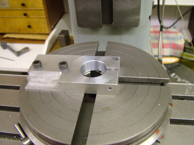
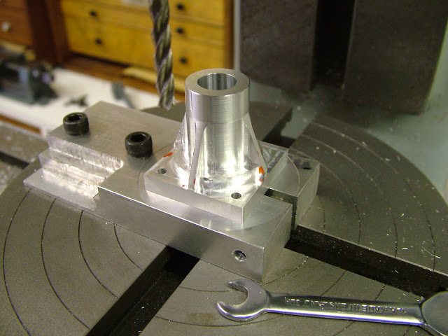
In the meantime I would like to drill and mill the transfer ports in the cylinder liners. I intend doing this with my lathe's milling attachment. I'm thinking of securing the liner vertically in the mill chuck with an aluminium "bung" in each end to improve the grip of the liner in the chuck. Since the chuck is hardened and ground I will probably slip a piece of emery paper between the chuck jaws and the bungs for added grip. Pics below.

All ports are located vertically with reference to the flange in the middle of the liner. Since I don't have a DRO, I plan to use my dial indicator to set the vertical slide for drilling the 4 holes. I will also need some method of keeping the liner centred as I rotate it to the 4 positions for the holes. Otherwise I'll have to re-find centre every time. Maybe a small V-block?

Please let me know your thoughts.

Chris

IMG_20130120_152218.jpg


IMG_20130120_161632.jpg


Screen Shot 2013-01-20 at 5.17.39 PM.png


IMG_20130120_140435.jpg
 
Hi Chris - Its all looking very good so far Thm: very nice work indeed.

Re setting up to mill/drill your porting.

Radially these are not too critical as long as they align reasonably well with their respective passages but relative to each other vertically and to the flange certainly is, for any deviation here will affect the timing as designed.

Going about it it as you envisage will require breaking the set up for each hole but there is a method by which you can set up just once and it will also allow the radial movement with a degree of accuracy

First off is to make a plate clamp from a piece of bar wide enough to fit in your vise but allow the cylinder to be outside the jaws. Something like this ....
DSCF0201.JPG


This type of clamp, if made to a reasonable fit on your cylinder, will exert a high degree of clamping pressure with very little torque on the clamping screw
DSCF0208.JPG


If you scribe a line across the diameter of the bore on the plate and two more at the angle of the transfer ports then a single line on the cylinder aligned with each will give you the radial movement required by releasing the clamp screw and rotating the cylinder without losing its vertical or horizontal alignment. That way the 3 x .5 passages can be milled last of all without moving the slide other than for the vertical displacement of the holes

Given what you are doing I would think that something about 10mm-3/8 thick ali or steel would be more than enough.

If required the plate can be recycled over and over for other parts and has many uses - R/T, Faceplate, Angle plate etc

There may be other ways to approach it but with the kit you have available this does mean you only set up the once.

One last point - if you feel something may move in a vise or clamped to a table then inserting a plain piece of copy paper will give you all the grip you need to prevent movement. There is a certain amount of 'give' in emery - particularly cloth - and parts can sometimes 'skid' on the grit or the backing

Regards - Ramon
 
Ramon,
That's perfect. I never thought of that setup, so I'm glad I asked the question. The scored lines will make setting the angles dead easy. I have a piece of ali perfect for the job.

Thanks for the copy-paper tip too.

Chris
 
Glad that's of use Chris

Something else that may help too is before you do this op is to turn up a slug of ali to a nice fit in the liner and drill the port holes through into it. This will keep the burrs in the liner to a minimum but twist and remove the ali to break the burr after each hole otherwise it will prove much more difficult to remove. Just make sure you drill into a fresh area on each hole.

Regards - Ramon
 
Today I made the carby bodies. Then I made up the plate clamp Ramon recommended. This clamp works beautifully in the lathe vertical milling attachment. I used a dial indicator to set the height of the intake and exhaust ports.

My tailstock chuck only closes down to 3mm so I had to use the chuck from my pedestal drill in the headstock to drill the 2mm intake port. This chuck has horrendous runout, but I was still able to get a nice clean hole by drilling 1.5mm first. Using the aluminium plug (again recommended by Ramon) kept the bore nice and clean. This port is meant to be centred 4mm from the flange. As best I can measure, it ended up around 3.8mm. Hopefully that is OK.

For the exhaust port I used a 3mm 2-flute slot drill with a 6mm shank. This allowed me to fit the tailstock chuck to the headstock spindle. Despite the much reduced runout in this chuck, I got a lot of chatter drilling this hole. I suspect the hole was not located exactly right and the slot drill was clipping the flange on the liner. As you can see, the hole is a bit messy and it cuts slightly into the flange. It is meant to just touch the flange. Hopefully the slight misalignment of the exhaust port won't adversely effect performance too much. I will need to de-burr this hole. Not sure what the best way to do this is. Any suggestions?

I'll hope to do the transfer ports tomorrow. I will use the slot drill for these too.

Chris

P1030929.jpg


setting height for drilling ports.jpg


drilling intake port.jpg


exhaust port.jpg
 
Hi Chris, Just caught up with this.

Glad the plate worked okay for you - I'm a firm believer in them for all sorts of ops.

Re the cutter giving you problems looking at the pic I'm assuming you plunged this through like a slot drill (which it is of course) however given you are holding this in a drill chuck it would be much better to centre drill, then drill say 2.5 then open up using the 3mm FC3 cutter. The problem arises in the cutter is trying to cut on the centre line and the chuck isn't rigid enough to hold the shank - hard jaws on hard steel are not a good combination. A little tip is to make a split brass collet to slip over the shank of the cutter - or even a shim cut from an ali beer can- you will get a much better grip that way

If the holes are displaced from the position as drawn it will alter the timing. They need to be relative to each other as best you can get it but it's not absolutely critical however the more deviation the more the potential for the engine not running as well as it should and you could be chasing all sorts of problems when you come to running it, not thinking that the timing could be wrong. As you have it it just means an earlier exhaust opening - shouldn't cause too much problem. Deburring - about the only thing is a nice smooth needle file, I have a few half round ones the very tips of which are ground like a scraper which I find very useful.

Given your chuck set up if you have a smaller FC3 cutter 2-2.5 then I'd run that down the port slot first leaving about .1 in the bottom then finish with the 3mm. If you dont have anything smaller then do it in several .15 passes. This will give the cutter the best chance of not pulling over to one side or over widening the slot -though that's not critical at all.

Hope you don't mind my input

Good luck with it - Ramon

Just thought - I think you said you have collets - make a steel holder for the FC3 cutter that you can hold in a collet - ream it 6mm and cross drill for a grub screw - much better;)
 
Thanks Ramon. I certainly don't mind your input. You've saved me a lot of pain so far.

Yes I did plunge the cutter in one go. Next time I will drill 2.5mm first as you suggest. I'll make a small scraper like yours to deburr these holes.

I will buy a 2.5mm FC3 cutter and do the slots in two passes. I couldn't bear to ruin a liner at the last step.

I do have an ER40 collet chuck, but I don't have a 6mm collet. I will order one, but postage from Hong Kong is taking forever at the moment. In the meantime I'll turn up steel holder to allow me to use the FC3 cutter in the 12mm collet.

I ran the timing calculator on Ron Chernich's website using the hole displacements I have achieved and compared them to the design timing figures. To my inexperienced eye, the 0.2mm error in the inlet and exhaust ports didn't seem to make a lot of difference. I guess I'll find out when I try to start them.

Chris
 
Hi Chris, I don't think I explained the FC3 holder too well

If you take a short 60mm long or so peice of steel say 20 mm dia that will fit a collet you have then drill and ream that 6mm. Cross drill that to take a grub screw and that will hold the cutter much more rigidly than a drill chuck. Oh yes, it wont be so important on this op as the cuts are very fine but always, just as you nip the screw up, pull the cutter outwards onto the screw. If pushed backwards which is the natural temptation the cutter can pull itself outwards on the helix if cutting on the side plunging the cutter deeper into the work.

In commercial use the original FC3 cutter holders were nothing less than above with a screw thread on the end to fit into a Clarkson milling chuck.

You're on the right track using Ron's calculator - a real asset. If you are not seeing too much increase in exhaust opening you should be ok.

Glad to be of help - I'll keep following

Should be making a start on my new engine this week - drawings are near finished.

Regards - Ramon
 
Ramon,
I started making an fc3 holder today. It's 16mm OD as that is the biggest collet I have. It will have to wait until I get my 6mm reamer next week before I can finish it. Progress has stalled until I get my 10mm collet and reamers. In the meantime I will make some laps and the offset jig for turning the crank pin.

Good luck with your new build.

Chris
 
Not much progress on the Midge while I await some tools. I’ve made the crankcase backs and the cylinder lap. Which leads me to a few questions about lapping. I know what I’m trying to achieve- a smooth bore with a very slight taper that tightens above the ports. I’m still not sure of the technique.

Do you lap with the lathe running in back gear while moving the liner back and forth along the lap to produce a crisscross pattern on the liner?

When lapping the piston to fit the finished liner, you obviously must periodically slip the liner onto the piston to check the fit. How do you prevent the course grit on the piston from scratching the nice shiny bore of the liner? Do you clean the lapping compound off the piston each time you check the fit?

I'm not having much luck finding carbide powder in the grits I need, so I will probably get myself an ultrasonic cleaner and use diamond paste. On eBay there's set of 12 x 5g syringes of diamond paste from 40 micron down to 0.5 micron for $25 delivered. The grits I need are covered in that range, but I have no idea how much I need. Will 5g of paste do 2 pistons & 2 liners?

Chris

P1030948.jpg


cylinder lapping tool.jpg
 
I lap my liners before I make my piston. Then, I make the piston and contra to fit. Sometimes I might tweak the liner open a little after I make the pistons, using the lap. Sometimes I end up making more than one piston or contra to get the fit right. It's a heck of a lot easier to remake a piston than a liner. I always clean the parts in the ultrasonic prior to any test fitting. I also scrub the liner with a Q-tip to get more crud out.

Your diamond paste kit will last you four lifetimes. You should need a tiny drop for each liner at most. I usually start with 15 micron or coarser and finish with 3 or 6 micron, depending on the size of the engine. I think I used 6 micron on my Midge.

I lap at around 350-600 RPM, moving the part back and forth to create cross-hatch. I use light spindle oil as the lubricant. I don't fart around much with trying to embed the grit in the lap by rolling or hammering. I get good cylinders just by smearing the tiniest dab of diamond onto the lap and then a couple of drops of oil. I dwell or make short strokes on the places I need to enlarge. I use the kind of lap you show and orient the liner with the bottom toward the screw end. This helps form the desired slight taper in the right direction.
 
Hi Chris , I would totally endorse the methods and technique that our friend RK has said. When it comes to the amount of paste it really is very small indeed. However, personally my only reservation is the lap itself. That is not to say it won't work as obviously RK vouches that it does but the method does mean the taper is the wrong way as the liner needs to push on the lap bottom end first to be able to taper the bore below the exhaust. The technique for that is to let the cylinder dwell on the lap in that area as well as to lap in that area slightly more than the bore itself. As said previously the amount of taper is virtually immeasurable with normal means but you will feel it whilst lapping as it loosens off in that area. The object of tapering this area is to reduce friction where a seal is not so important. It also makes for an easier start to ensuring the piston is lapped to the bore without going undersize. Bear in mind when 'going undersize' on these engines you are talking very small tolerances indeed.

Lapping is a pure hand skill and one which practice makes perfect. I would certainly bore a couple of scrap pieces of steel to practice on before diving in on the liners

I imagine also that the type of lap you have made will also wear on the point of expansion and not remain parallel along itself but on the otherhand it may soon 'lap itself' to the bore however any expansion would surely repeat the situation - How have you found this to work out in practice RK ?

The other thing I would be extremely wary about is the screw - it would be very easy to catch the bore and mark it on the head. Definitely not worth the risk at this stage. I would make this as short as possible and either use a grub screw or remove the head and cut a slot in for a screwdriver

As RK says by the time you get to fitting the piston you should have the bores finished and the piston lapped using an external lap so that it will just fit into the lower part of the cylinder. It's from that point lapping the piston to the cylinder takes over - by comparison this is a slow process as this is where you can make or break the fit you need with ease.
Use a microscopic amount of of the finest grade paste and plenty of lubricant then using a tee bar handle slowly wring the piston in the bore rotating it side to side and gently applying pressure forwards and backwards up the bore. Once the piston is in the bore to its (the pistons) full length, remove, thoroughly clean and lubricate and try in the bore.You may have to do this severral times before eventually the piston wears to the point it will slowly increase its depth in the bore until suddenly it will enter the upper bore. Stop at this point - another thorough clean, lube well and try. If the fit is right you should not be able to push the piston all the way down the bore holding your thumb over the top to seal it.

If the piston siezes at any point during this lapping process dont panic and try to wring it out with the handle - just insert a piece of wood dowel the other end and gently tap it out. Dont put any more paste on but give it plenty of lube and start over. Plenty of lubrication is better than less whilst lapping. - Its a messy process make sure your lathe is well covered to prevent the paste/waste getting on the ways

There are quite a few pics on the Tigre thread of these ops which you may have already seen
http://www.homemodelenginemachinist...g32-1cc-diesel-5cc-version-17674/index16.html

Sounds like you are getting close - I'm about to start machining today

Regards - Ramon
 
I forgot to mention that I now use two laps, one for coarse and one for fine lapping. I have done it successfully with a single lap. I don't use a piston lap. I simply make an extra-long rod and polish the OD with 600 or 1200-grit paper and oil backed by a steel rule until I get the fit I want. I make the pistons from this rod. I face off a good chunk of the rod end to avoid barrel shape. I make the pistons tight and then fine tune the fit by lapping the liner some more.
 
Gents,
thanks for the very detailed answers.

I will order the diamond paste kit from eBay. Sounds like I'll be passing it down to my kids!

I will replace the SHCS with a grub screw.

I'll have a think about whether to lap the pistons to the liners (Ramon) or vice versa (RK). I guess I want the most foolproof method. I have already turned my CI piston stock down to 0.5mm oversize and long enough to make 2 pistons and 2 CPs plus some fat (see pic). My only worry with your method RK is that I might polish the piston stock undersize at the chuck end but I wont know about it until I have parted off the first piston and CP. I suppose I could just polish the end of the rod for one piston and CP, part them off and then polish the second piston and CP? I'll have to sleep on it.

Chris

IMG_20130117_120529.jpg
 
Good morning guys,

Well I finally made a start on making swarf so its nice to be back on the lathe :)

Thanks for the info RK - there is indeed always more than one way to skin the proverbial cat.

I have a couple of reservations in this instance with Chris's lack of material but that is not however to disagree nor denigrate your methods - you've made some very nice engines to prove your way works too.

My main thought is on tolerances - piston to liner. By making a long rod from which to part off the piston means the liner has to be lapped to fit which appears to me to be trial and error until the piston will fit. That presupposes if there are multiples the bores are more or less identical. As I envisage it by doing them individually there is much better control one to one. There is also the wastage of material to consider as opposed to parting off a piston then holding it in a fixture for lapping.

As I'm sure you are only too aware the tolerances are microscopic, part to part, to obtain the right fit - I feel by lapping the piston to the bore that is as close as you can get with the usual basic kit at our disposal and especially if the bore is tapered. However as said the proof is in the pudding and your engines bear testament to your method. As always I guess 'you pays yer money' etc

The other thought is concerning the piston internal machining. If this is done on the lathe in situ then the piston has to be presented to the liner skirt first. If the inside is machined after then there is the possibility of distortion after lapping. Having suffered that latter on the Racer build I'm reluctant to finish turn and lap until all stress of internal machining are relieved.

As said this is not to disagree just thoughts from a different direction - I'm sure you would agree however that this one part of the build which has to be got right to achieve a runner - after all 'no compression - no ignition'

Chris - at .5mm up on diameter you still have enough material to part off a piston and hold on a fixture for final turning/lapping should you so choose. I usually leave about .075mm max on for lapping. Failing that I would only turn the stock you have reduced enough for one piston to this size plus a little, run a parting tool in to creat a shallow groove then lap either with a flat stone or as RK suggests with 600 grit stuck to something flat. That way you will save material. The groove will allow the 'lapping stick?' to overlap. If you do it this way, one by one ie one piston first followed by the next then the two contra pistons last you will have more control. One other thing the flat piece of material you choose for sticking the 600 grit to wants to be less than or just wide enough to cover the piston width - too wide and the tendency will be to taper the piston.

Now - I'm off to make some more swarf ;D

Regards - Ramon

Oh yes, For those who may wonder I'm posting about this Eta engine build this time over on Model Engine Maker
Having done the Tigres on here I thought that best and will cover the next build whatever that might be on here.
 
Ramon,
thanks for your wise counsel. I have re-read your Super Tigre thread and the process is very well explained there. I will follow your method.

That's not to criticise RK's method, but I feel with my complete lack of experience with lapping, parting-off before lapping will give me individual control over each piston-to-liner fit.

I finally have a set of M2 taps, a 6mm hand reamer and 10mm ER40 collet. I will bore and tap the crankcases this weekend.

I went to my usual fastener shop yesterday and bought the M2 screws for the heads and crankcase backs. He only had stainless steel screws in that size, so I bought them. Will these be OK in aluminium?

Chris
 
Hi Chris, I'm sure RK won't be put out by that -this is a big step you're taking with little material to play with.

M2 screws eh? Well that goes to show how small the engines are you're making ;) - Yes stainless will be fine

Have a good weekends machining :)
Regards Ramon
 
Simply go to your local car repair shop and ask for a very little amount of valve seat grinding compound.
 

Latest posts

Back
Top