ML Midge Build

Home Model Engine Machinist Forum

Help Support Home Model Engine Machinist Forum:

This site may earn a commission from merchant affiliate links, including eBay, Amazon, and others.
The abradant will break up during the lapping process, forming smaller grit.
 
Progress has been slow. I have finally bored the cylinder liner hole in each crankcase.

I am now finishing the liners. I have drilled the 4 ports in each liner and I am about to start milling the transfer slots. I was planning to start with a 2.5mm 2-flute slot drill and finish with a 3mm 4-flute end mill. However I would like to clarify an issue with the size of the slots.

I have 2 sets of plans- the original inch plans by Mark Lubbock and a metric set by Ron Chernich (which I have been following to date). The transfer slots on the metric plans are quite a bit bigger than those on the inch plans:

Metric plan slot = 3mm x 0.5mm = 1.5mm2
Inch plan slot = 2.4mm x 0.38mm = 0.91mm2
Transfer port = #50 drill = 2.48mm2

As you can see, on both plans the transfer slots are substantially smaller in area than the ports they supply. But the transfer ports on the metric plans are 65% bigger in cross-section, making them closer in size to the port. I'm inclined to use the larger slots from the metric plans for better flow, but that only leaves 0.5mm of wall thickness on the liner. Is that enough?

Why are the transfer slots much smaller than the ports? Is this common on 2-stroke engines? :confused:

Chris

P1030958.jpg
 
Hi Chris - from what you are stating I'm assuming the wall thickness of the liner is 1mm - I've just spent a while trying to find the drawings on MEN both on the web and on the MEN members disc to no prevail -

.5mm wall thickness should be okay and should not cause any problems but if you are concerned go to .4 depth and compromise - it should have little effect, if any, on performance and you can always deepen them later should you really think it neccessary.

I really don't have enough knowledge to answer your last question specificlly but -and I don't wish to be seen as flying in the face of so much that has gone before on these small engines - I've long thought that transfer passages especially in cast cases always seem excessively large in proportion to the fuel required to be transfered - indeed as I see it the larger these passages the bigger the case volume the less the pressure created to transfer the fuel - but then I have no training in such matters and may be totally on the wrong track so don't take that as a guide :rolleyes: The ports themselves obviously only allow fuel through to the limit that the piston opens and closes it - the bigger they are then I would say, within reason, the less restriction in fuel transfering

On the Eta engines I made, the passages in the liners are cut much as the Midge but the case itself is relieved inside to give an increased volume to the passage. There's no way of measuring the volume in the original but proportionally the original 15d has probably twice the volume than my 5cc version. All these 5cc versions run extremely well and give no impression that not enough fuel is available because of the relatively much smaller passages.

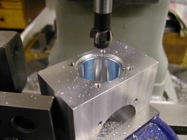
This pic might help - but you will need to make a cutter if you go this route. The passages here are just 1mm deep but there are four of them.
DSCN2746.JPG


Good to hear you've made some progress - my basic cases are nearing completion I'm pleased to say

regards - Ramon

PS Have you got a link to the drawings or did you have to buy them ?
 
Hi Ramon,
Yes, sorry, the liner walls are 1mm thick.

I bought the plans in PDF format. There are a couple of screenshots below. The original imperial version with the metric equivalents in red and Ron's metric plans. I think Ron has just rounded to the nearest 0.5mm on his plans. I'm not sure if he has actually built an ML Midge using his own metric dimensions. I'm inclined to use the original dimensions for critical parts like the liner. That's why I drilled the transfer ports #50 and not 2mm.

Are you going to post a thread detailing your new build?

Chris

Screen Shot 2013-02-14 at 9.22.49 PM.png


Screen Shot 2013-02-14 at 9.23.48 PM.png
 
Chris, As I'm sure you are aware it's the very top of the transfer port that matters not the centre of where it's drilled. Looking at these two drawings then Ron's version has the hole centre the same relevant to the flange but with a .22 larger hole places the opening point .11mm further up the bore ie an earlier opening. Whether that would make significant difference to the running at this size I'm not sure. In keeping to the original on port size #50 you haven't changed anything - the width of the passages as already said is not so critical.

Are Rons plans viewable on MEN - I can't find them so far.

The current build is for some new Eta engines and the build for the Mks1 and 2 is destined to be published in ME magazine around April/May time. I have posted a few pics and update on Model Engine Maker but as I don't want to pre-empt the article the pics are being kept to a minimum. I haven't posted about them on here because of the recent Tigre thread besides to post on both sites demands too much time but I will post the next I/C build on here as opposed to MEM
 
Why are the transfer slots much smaller than the ports? Is this common on 2-stroke engines?
confused.gif

Transfer ports should never be smaller then the channel
the size difference create a pressure and help your cylinder scavenging


Hi Luc - Given the very small amount of material that Chris has to play with it's going to be difficult for him to achieve that given the areas quoted are correct - and I assume they are. Perhaps thats why Ron widened the slot on his layout. The only way would be to decrease the area of the port or to widen the slot. Indeed providing they don't break into anywhere they shouldn't the 'slot' could just as well be a flat milled across the liner at two points to give crescent shaped passages.

I do agree though that the passages should be big enough to carry enough fuel for good scavenging but - ah theres always a but ;) - at this size and this type of low speed engine is that as quite as important as in something much faster and more powerful?

Regards - Ramon
 
Ramon,
Yes I was aware that the top of the transfer hole is critical. After liaising with Ron I decided to drill the holes #50. I don't know if Ron has actually built the engine using a 2mm hole. As you say, I can always enlarge the hole later if I need to.

I look forward to the ME magazine article.

Chris
 
Transfer ports should never be smaller then the channel
the size difference create a pressure and help your cylinder scavenging

Hi Luc,
just to clarify, my transfer ports are larger than the channels.
Chris


oops - just realised I misinterpreted Lucs reply :rolleyes: - call it an age thing

Ramon
 
Hi Luc,
just to clarify, my transfer ports are larger than the channels.
Chris


:wall::wall: some big typo from my side:wall::wall:

the port (hole in your case) should be smaller
then the transfer it self. see this in reality use a garden hose and squeze
the output with your finger. You can direct or scavenge your water
the same thing happen with your motor. I would make the hole smaller
then rquest then finish it up with a dremel with a rectangular shape pointing
to 50 degree instead of 45

cheers
 
Thanks Luc,
I thought that's what you meant. As I have already drilled the ports I will use the larger slots size recommended by Ron.
cheers,
chris
 
Thanks Luc,
I thought that's what you meant. As I have already drilled the ports I will use the larger slots size recommended by Ron.
cheers,
chris
this is what your angle should look like
the smaller the engine better the scavenging must be

scavenging angle2.jpg
 
Thanks Luc.

I drilled and tapped the M2 holes in the crankcases over the weekend. All 16 of them. It was a very tedious job, but I had to stay focussed because a broken tap would have been a disaster. One of the backplates isn't seating properly. I think I have a burr around the rear hole in the crankcase. Also the cylinder liners aren't fully inserting into the heads. I will need to mount the heads on some sort of fixture and clean up the top with the boring tool.

Chris

finished crankcases, backs & heads 1.jpg


finished crankcases, backs & heads 2.jpg


tapping M2 threads.jpg
 
I built my Midge per Ron's plans including the transfer slots and ports, and it starts and runs very very well.
 
I built my Midge per Ron's plans including the transfer slots and ports, and it starts and runs very very well.

I never assume it would not, but there is a difference between
VERY VERY WELL and
Excelent
 
Yes, one is an adverb and the other is a misspelled adjective.

probablement que vous ne pouver pas ecrire en francais pourquoi chercher
les erreurs qu'an on écrit en englais.
devenir vieux est une chose, devenir impolit en est une autre.

I hope that one day you can understand my french, and realise your not up to my level YET:mad:
 
Back
Top