Milling Table Stops

Home Model Engine Machinist Forum

Help Support Home Model Engine Machinist Forum:

This site may earn a commission from merchant affiliate links, including eBay, Amazon, and others.

cfellows

Well-Known Member
Project of the Month Winner
Joined
Aug 25, 2007
Messages
3,890
Reaction score
715
I have recently come to really appreciate adjustable stops on my milling table.

28cc741f.jpg


Some months back I installed the Igaging DRO's on my mill/drill, but they just aren't built well enough. I won't go into the why, but my setup only lasted about a month then quit working. Plus, the readouts are too hard to read. And, stopping the movement of the table at an exact reading is difficult and stressful.

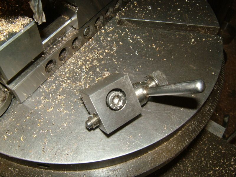
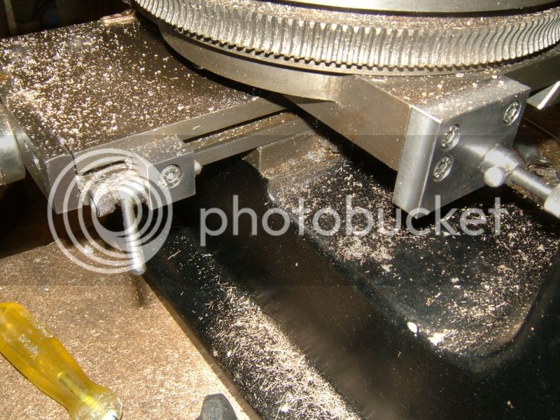
So, I removed the DRO's. I had made the two aluminum blocks in the picture, plus new brass dovetail nuts behind them to hold the Igaging scale. I discovered after removing the scale, that the new nuts and aluminum blocks made a very secure stop, much more secure than the ones which came on the mill/drill originally. So, I've been using these a lot, especially with my V8 engine which requires a lot of repetitive cuts. I used the stops, also, for example, when making the 1/8" wide slot in the bottom of the piston. I find the stops are much better than a DRO for these applications because you don't have to watch for anything... you just stop cranking when the table stops moving. It is also, in my case, much more repeatable. And, it's a heck of a lot cheaper than a good set of DRO's.

DRO's are certainly good for a lot of other things. But for simple repetitive milling operations, stops are hard to beat. Now I have figure out how to install some stops on my Y-Axis.

Chuck
 
Hi Chuck, I agree that stops make repetitive work a lot quicker and easier!

For the Y-axis, drop a couple of brackets from the Y carriage and fit a bar of Suitable length, parallel with the table top, and a stop up from the base - a pair of clamps on the bar, and hey presto, Robert is one's parent's sibling - I did a little Crap-O-CAD at http://www.chaski.org/homemachinist/viewtopic.php?f=43&t=93654 for a guy wondering about the X-axis on his mini mill, should be adaptable to the Y axis? If the carriage ways aren't widely enough apart, you could use a pair of bars of the length you need spaced 1/4" or so, mount the "rear" one to the drop brackets, clamp on the front one?

Dave H. (the other one)
 
Chuck

Last year I changed my Emco FB-2 for a fancy German mill. Big mistake. Among other disappointments, there is no provision for fitting table stops and I miss them. Like you say, DROs are fine for most things but you can't beat the mechanical stop for many jobs.

Dave
The Emerald Isle
 
I have to agree , I also dumped my DRO and fitted stops on my BCA
DSCF4698.jpg

the Y axis was more difficult and as yet I have only fitted one
DSCF4699.jpg

but it allows very accurate re-setting of the rotary table to dead centre.
 
Thanks, all, for the comments. I need to fancy my stops up a bit so they are easier to set and micro adjustable, like Abby's, wouldn't hurt either. still have to take time to figure out the Y-Axis. While I'm at it, I also need to replace the factory Z-Axis stop with something more exact and a lot faster to set. Anybody got any ideas?

Chuck
 
SOS SOS SOS.

My Japanese Sakai Vertical Mill has no tee slots on the front side.

Please give Gus some suggestions.
 
SOS SOS SOS.

My Japanese Sakai Vertical Mill has no tee slots on the front side.

Please give Gus some suggestions.

Let's see a couple of pictures of your mill table Gus and maybe we can come up with some ideas! :)

Vic.

Update, thinking about it a couple of options spring to mind.

You could utilise the existing T slot on the top of the table by making some angled brackets to use as stops or you could drill and tap a couple of holes on the front of the table to mount some sort of rail to which stops could be fitted.

Foto attached. All suggestions welcome.:):) Milling tee slots w/o stops was tough.Had to rely on the marked lines. Torch lite and brush help ensure not overcutting. Rotary table now have a not so bad looking slotted table. With this sphereical weights for the speed governor were successfully done.

IMG_0464.jpg
 
I agree Chuck, table stops are very useful, almost indispensable for me. You may like to look here it may give you a basis for some Y axis stops. One advantage is that it did not need any holes drilling in the machine.

Actually, I have no problems with drilling the machine if I could move it to the drilling machine but do not like using a pistol drill for the purpose.

They are not quite as definite as the X axis stops but good enough for most applications. When the position is critical one can always refer to the leadscrew dials, but using the stops as an indication that you are very close.

I added them many years ago when I needed to make a deep recess in a piece of steel, the four stops setting length and width.

The above link shows that I used them to set the width of the spokes on some clock wheels I was crossing out, the X axis stops set their length.

Harold
 
Good find Jim. Yes thats one of the options I envisioned, provided Gus does not mind drilling into the table.

Vic.

Hi Guys,
Thanks for the idea and I am biting though the fish today did not bite.Fishing was dull.But the company was good.

I have ample material on hand to make mill table stops.
 
Actually, I have no problems with drilling the machine if I could move it to the drilling machine but do not like using a pistol drill for the purpose.

I agree. If I had to do it I would accurately drill a "jig block" and clamp this to the machine as a guide for the drill.

Vic.
 
Hi Guys,
Thanks for the idea and I am biting though the fish today did not bite.Fishing was dull.But the company was good.

I have ample material on hand to make mill table stops.

Let's see some pictures if you proceed Gus, we like pictures! th_wwp
 
Let's see some pictures if you proceed Gus, we like pictures! th_wwp

Sure hate to use pistol drill to drill into table side. Just hatched an idea,using the table top slots and come out with a detachable stop.

Most likely by latest this/next week a proto type comes out.


Need some advice bofore I sink into this potential quagmire while trying to built attached.Have built one simple model aeroengine due lack of hands on experience ,have yet to complete and run live.
Material just arrived.Now doing a Work Instruction Sheet as per ISO 9002 procedure with all steps written down. Sure hate to contribute to the reject heap.

IMG_0516.jpg
 
Let's see some pictures if you proceed Gus, we like pictures! th_wwp

See attached foto. The folly of not using table stops.
My eyes nearly dropped and brains nearly went blank.Rotary table top made it.
Gus did not overshoot when "tee Slotting. Pardon the wee bitty rust.Here in Singapore everything goes rusty including 69ner Gus.

Rotary Tables are expenive.The cheapest from China was US$320 and it was sold under European Brand. European 4" Rotary Table made in China.I made mine for less than US$70.The Japanese worm and wheel cost US$40.
Latest. Bought worm and 40t wheel for US$4.00 Will use these to make divider head to cut clock gears. Plans came from UK Author----Harold Hall.

IMG_0524.jpg


IMG_0508.jpg


IMG_0484.jpg
 

Latest posts

Back
Top