MILLING MACHINE TABLE TRAVEL STOPS

Home Model Engine Machinist Forum

Help Support Home Model Engine Machinist Forum:

This site may earn a commission from merchant affiliate links, including eBay, Amazon, and others.

Brian Rupnow

Design Engineer
Project of the Month Winner
Joined
May 23, 2008
Messages
14,991
Reaction score
8,285
Location
Barrie, Ontario, Canada
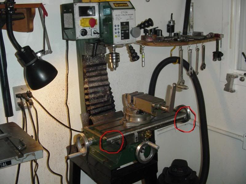
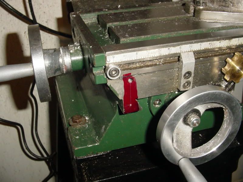
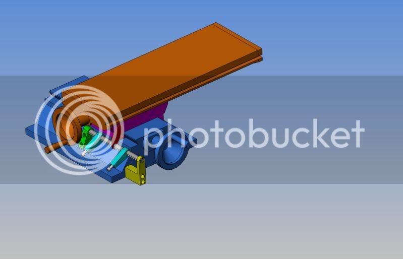
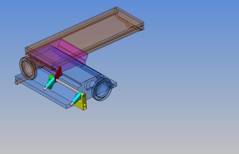
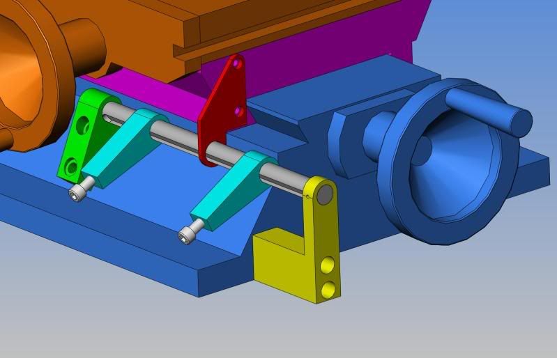
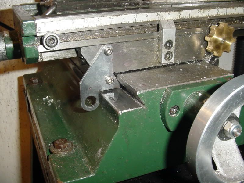
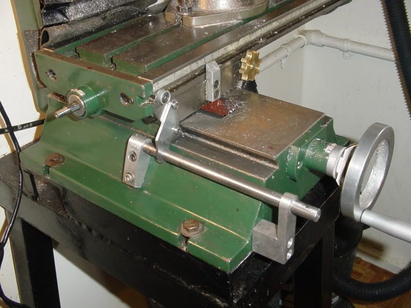
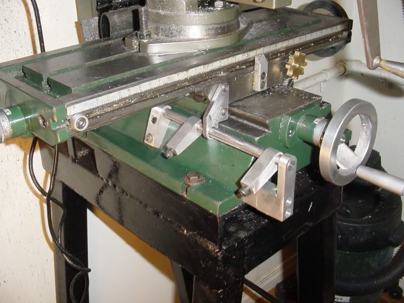
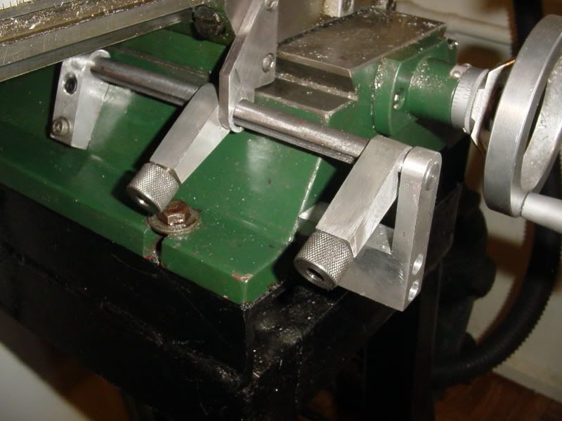
My imported milling machine (Busy Bee CT129) has a provision for setting "stops" on the left/right travel of the table (shown in highlighted circles). I find them very handy, and use them a fair bit. The only problem is that the machine has no provisions made for travel stops on the Y axis of the table, front to rear. In my continuing saga of trying to keep myself occupied until I get some "real work" I have decided to design and build some "adjustable stops" for the Y axis travel of my mill.
MILLTABLESTOPS001-MARKEDUP.jpg
 
This mill is a good value for the money it cost, but it had the most mickey mouse table locks for the X axis that I have ever seen. They were a lever type made out of plastic, and were long enough that they hung down and interfered with the Y axis travel. After managing to break both of them off because of their poor design, I built a new lock "handle"out of brass and installed it in the right hand hole, but left the left hand hole empty. Whenever I add to a machine, I like to use a machined surface as my "mounting point" so I decided to use this vacant threaded hole, and add a second tapped hole below it.
MILLTABLESTOPS003.jpg

MILLTABLESTOPS004.jpg
 
this looks like it will be a very interesting post.

i know what you mean about the table locking handles getting broken off, my old mill had the same problem.

chuck
 
As in all things, I decided to model it in 3D cad before I started cutting any metal. The red colored bracket is attached to the face of the Y axis slide, using the two threaded holes previously mentioned. The yellow bracket is a support which gets mounted to the front of the mill base. It supports the grey round rod (1/2" diameter). This round rod runs from the front to the rear of the base, where it is held by a second bracket. The blue "adjustable stops" are threaded 1/4"-20 and the 2" long socket head capscrews which pass though them seat in a slot which is milled in the 1/2" round rod. The rod is pinned in the yellow bracket so that it can not rotate. This serves to keep the blue "adjustable stops" at the correct angle for easy access.The red bracket doesn't actually touch the 1/2" rod----it has a 17/32" clearance hole though it. The model shown here shows the table at its maximum travel towards the operator in the Y axis. Everything clears the handwheel quite well, as I hate pinching my fingers when I am turning a handwheel.
TABLEATMAXTRAVEL-Y-AXISOPERATORSIDE.jpg
 
Here it is shown with the table at "mid travel" in the Y axis. The two "adjustable stops" are shown clamped to the grey round rod in a couple of arbitrary positions that I selected. You can see how the red bracket bolted to the face of the Y axis slide will stop when it contacts the adjustable stops. In this model you are able to see the green colored rear bracket which is mounted to the machine base as well.
TABLEATMIDTRAVEL-Y-AXIS.jpg
 
This model shows the table at its maximum travel away from the operator. The brackets supporting the rod and the length of the rod itself are designed so that when the table is at its maximum travel in either direction in the Y axis, there is still 11/16" clearance between the red plate and the brackets. The blue "adjustable stops" are 5/8" wide. I put the slot in the grey rod for two reasons----One as mentioned, to hold the "adjustable stops" at the most convenient angle, and Two--so that any burrs raised by tightening the 1/4" socket head capscrews won't mess up the outer surface of the 1/2" rod.
TABLEATMAXTRAVEL-Y-AXISAWAYFROMOPER.jpg
 
Well done Brian! That scheme looks like it can be applied to my RF30 with virtually no modification - a handy addition that I have been pondering for a while now. :bow: :bow:
 
Another part made-----the rear support bracket for the 1/2" round rod. I would have had the front bracket made too, except my poor old band-saw blade has gotten so dull that I could chew the bracket out of 3/4" plate faster than the saw will cut it. ----Had to phone the missus and grovel and whine so she will stop and pick up a new blade for me on the way home from work.
REARSUPPORTBRACKET002.jpg
 
Brian, looks like a good sensible simple modification...will have a look at my beasty to see if I can also do same... tah mate. Rob
 
Nice work!

Brian Rupnow said:
---Had to phone the missus ... so she will stop and pick up a new blade for me on the way home from work.
EXCELLENT work! :bow:
 
These aren't going to be much use if you don't have a CT129 mill from BusyBee, but since I had to make them for myself anyways, I'll post them just in case----
ADJUSTABLESTOP-DRAWING.jpg

BRACKET-1-DRAWING.jpg

BRACKET-2-DRAWING.jpg

ROD-DRAWING.jpg

PLATE-1-DRAWING.jpg
 
Brian, that is a project that is just in time, I just got the Harbor Freight mill that will be the first project on it, keep the pictures come also, question, how do you cut the Radius on parts like that, thanks again, Lathe Nut
 
I walk the part out to my old monster vertical sanding belt that I built a few years ago, with a #36 grit belt on it and do it by "eye". It works amazingly well, and with some use you can get "pretty accurate" with it.
 
Bit by bit progress is being made. My lovely wife stopped and bought me a new bandsaw blade on her way home from work last night, (and then took me out for dinner!!!) . While I was waiting for her to get home I milled the slot in the 1/2" round rod, and this morning I made the front bracket and then assembled things so I could drill and tap the holes in the mill base for the bolts to hold the rear bracket in place. I had to make the front support bracket out of 2 peices, as I didn't have any 3/4" stock big enough, but that won't hurt the functionality. (In the picture, you only see one part of the front bracket----the second part will be basically a spacer. I have to run up to the hardware store now and buy a 17/32" drill and some 1/4" socket head capscrews.-----Brian
REARBRACKETINSTALLED001.jpg
 
Well boys and girls---its finished. Two days "frigging time" but it works, and it works very well. For all of you who thought my 1/8" mild steel plate was too thin----You were right!!! It worked, but it did deflect enough that I wasn't comfortable with it---so----I made another out of 1/4" plate, and it feels a lot more "solid" when the carriage hits one of the adjustable stops. I have ran the table full travel in both the X and Y axis, and nothing binds, interferes, or pinches my fingers. I think the operation was a success---Now I have to figure out something to do tomorrow-----Brian
FINISHED001-4.jpg
 
Brian, thanks for the answer on the Radius and thanks for another neat project to make the machines give us better results, I have the larger verson of the HF mill the Zay 7032G that will work great on it also, copy paste and save to file time, thanks again, Lathe Nut
 
Being well known for "Not being able to leave well enough alone" I decided that since I had room for pretty knurled finger knobs, I would make some.----Thus justifying the money I spent to buy a knurler which has never been put to any practical use since I bought it! I had a piece of 3/4" "mystery metal" laying around, so I drilled it out to 5/16" diameter, turned down the heads of the 1/4" shcs. for a press fit, then silver soldered things together. I drilled the hole all the way though, so if I need to I can still tighten the shcs. with an allen wrench.
KnurledKnobs001-1.jpg
 
My self I don't think I would have removed the other table lock. Using just one all the to the far right is bound to cock the table just a bit. If your side milling a long part in the Y axis it may not be a perpendicular cut now. I lock both of mine on my full size knee mill just to be sure.
 

Latest posts

Back
Top