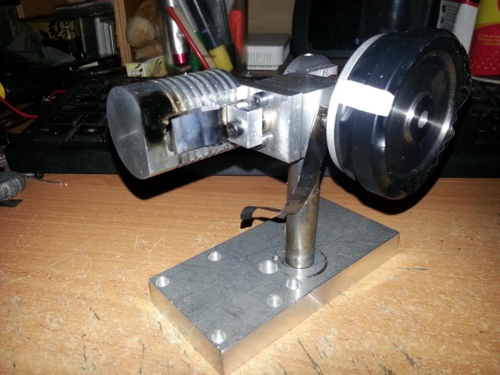
Metric Zippo Flame Eater

Home Model Engine Machinist Forum

Help Support Home Model Engine Machinist Forum:

This site may earn a commission from merchant affiliate links, including eBay, Amazon, and others.
Sweet! I can't wait to see it finished!

Pat on the back for sharing you drawings!

Be sure to put up video when you get finished! I'll be following your build!
 
Next lot of drawings.
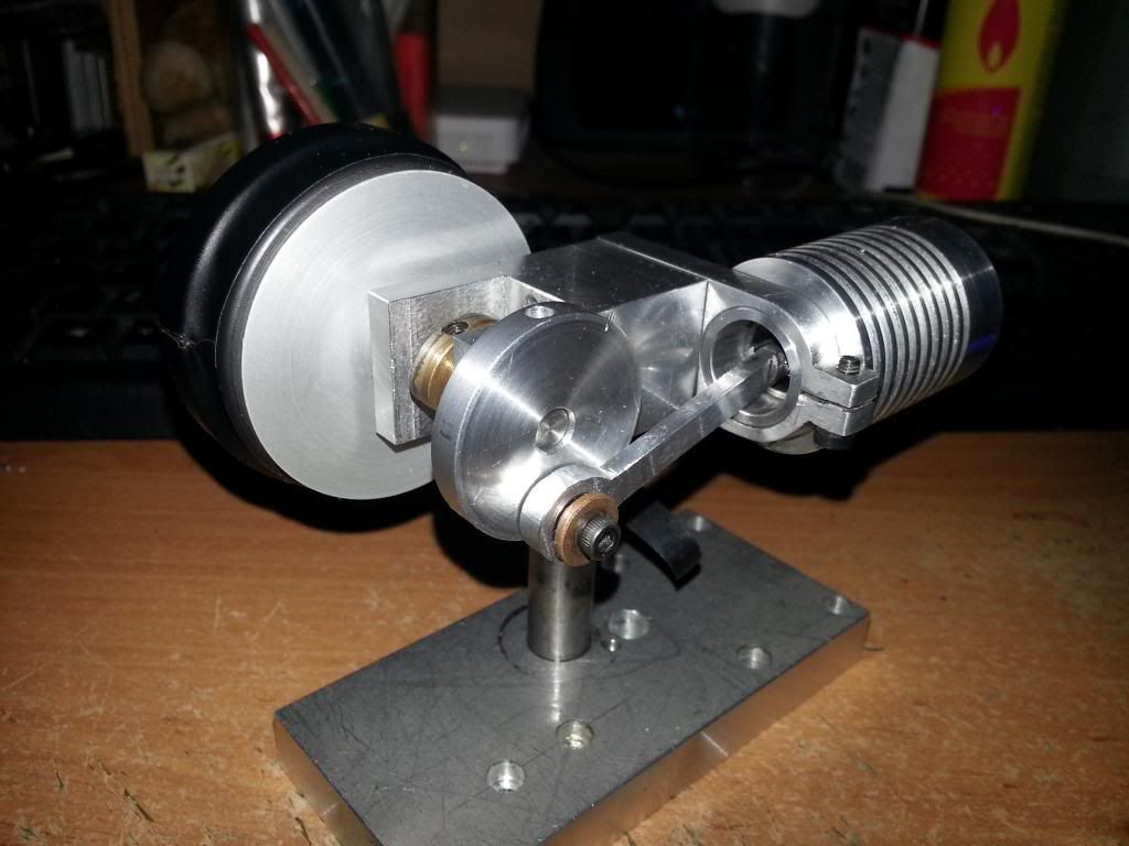
This is a good engine for those moving on from wobblers and is very forgiving as far as accuracy goes. As long as the piston and bore are matched, you don't need to be super critical with dimensions. It's easy to assemble and easy to maintain. Just 2 M3 screws to remove the cylinder and piston/conrod for de-sooting/cleaning.
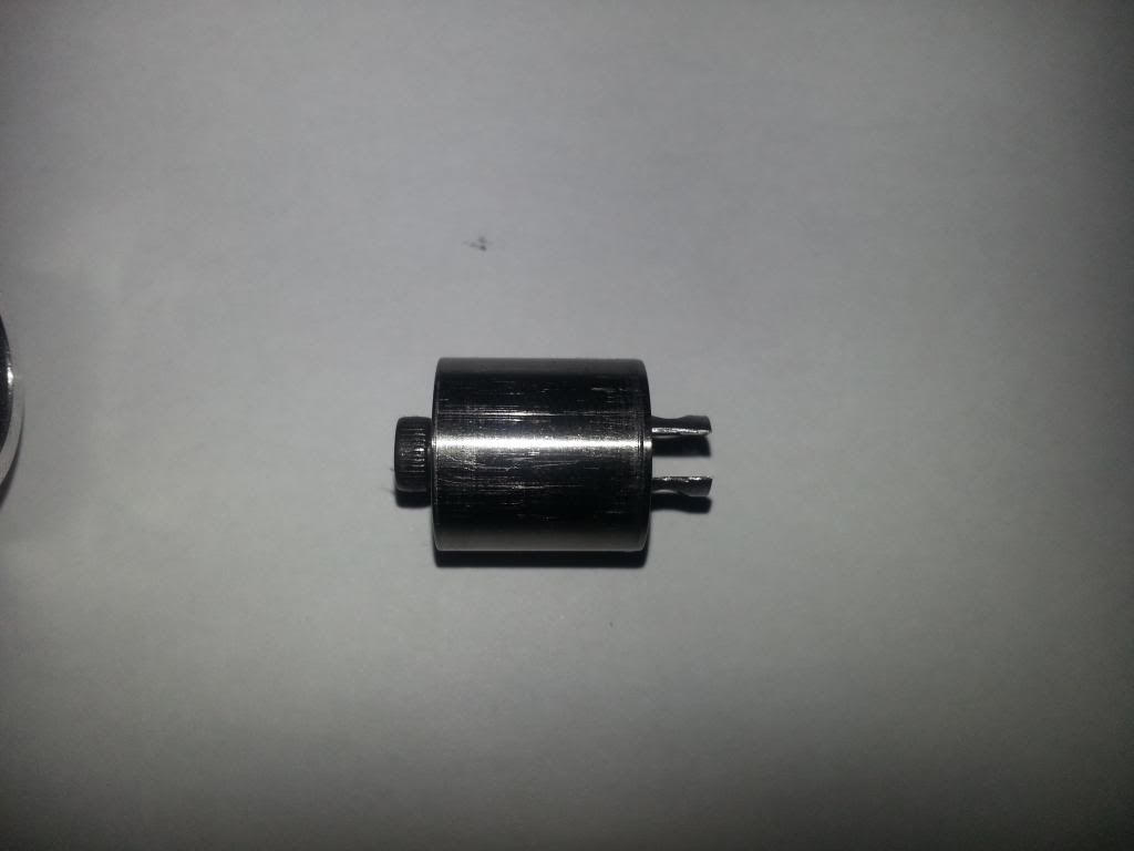
I used HE30 Aluminium for the cylinder and Titanium for the piston (I used what i had!)

More to follow!

Thoughts/comments welcome.

View attachment Cam.PDF

View attachment Con Rod.PDF

View attachment Crank Disc.PDF

View attachment Crankshaft.PDF

View attachment Flywheel.PDF

View attachment Piston Rod.PDF

View attachment Post.PDF

View attachment Washer.PDF
 
Thanks Woodster, a good project. And I like the Zippo twist.

Jim
 
Woodster--Thank you for the drawings. Your engine seems to run very well in the video. I will probably convert the drawings to Imperial units and redraw in Solidworks and maybe---Well, I get bored easily. My "Rupnow Engine" is finished now, and I'm just monitoring the progress of others who are building it. So---Maybe---I'll build a flame eater. I've never built one before.---Brian
 
Woodster--A few questions--What was the thickness of the main bearings. I can get the inner and outer diameters from the part details. what was the inner and outer diameter and thickness of the bearing on the big end of the con rod. What is the diameter of the wheel (I assume there was a wheel or bearing) on the end of the push-rod that rides up against the cam.---You left the length off the pushrod drawing, can you either add it to the drawing or just tell me the overall length.
 
Last edited:
No problem. The main bearings are 12mm O/D 6mm I/D 4mm thick. The conrod bearing is 8mm O/D 3mm I/D 4mm Thick. The spring is (as you guessed) to keep pressure on the cam and sits on the small diameter of the pushrod and butts up against the brass bush/guide. The pushrod roller is another 8 x 4 x 3 bearing held in with a 3mm dowel.
I haven't got round to a full parts or assembly guide yet, but i think you've worked it out.

Apologies and corrected drawing attached.

View attachment Pushrod.PDF
 

Latest posts

Back
Top