Machining a clearance for a flywheel

Home Model Engine Machinist Forum

Help Support Home Model Engine Machinist Forum:

This site may earn a commission from merchant affiliate links, including eBay, Amazon, and others.
Joined
Aug 21, 2023
Messages
3
Reaction score
2
Location
Tucson, AZ
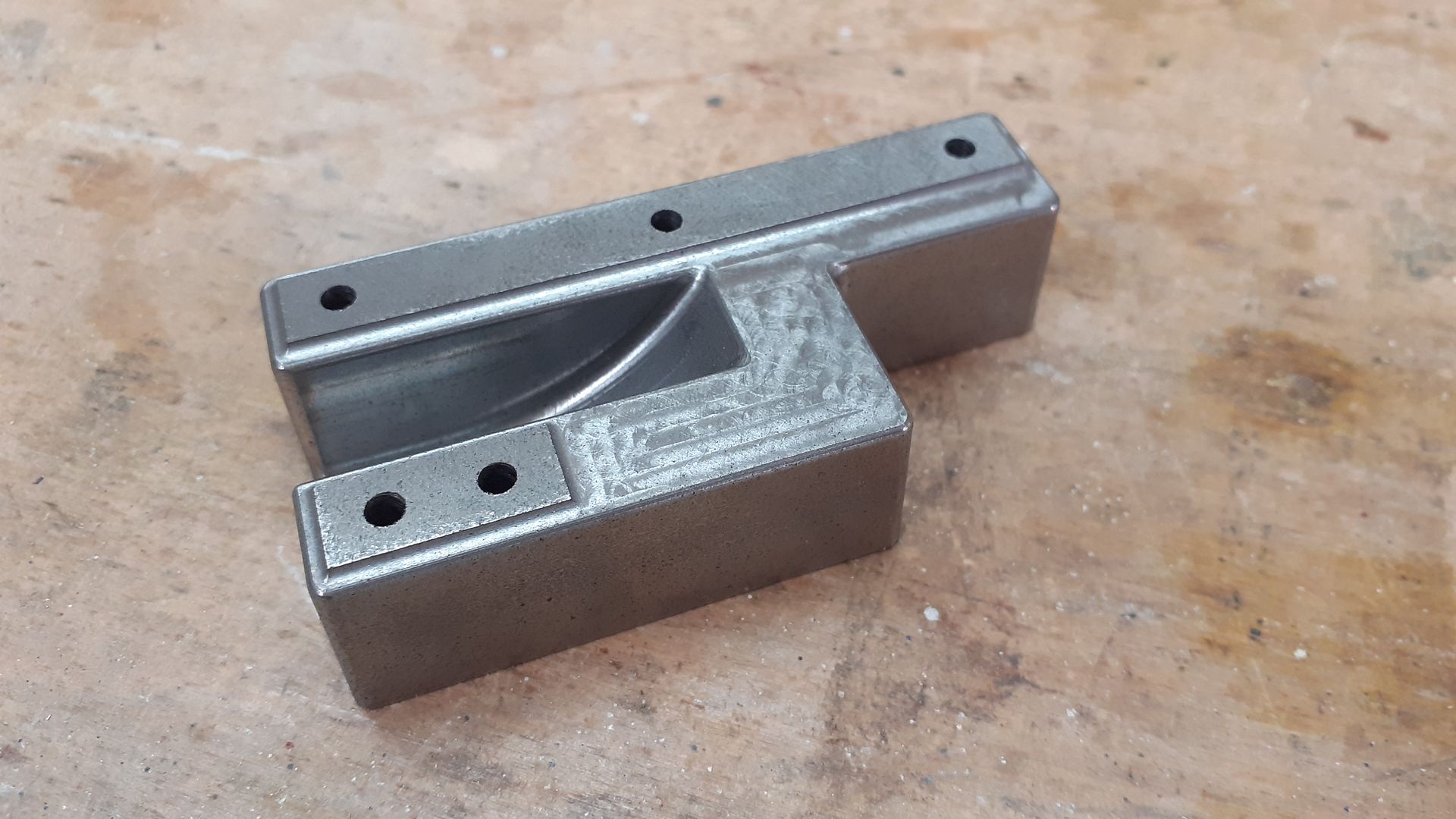
I have seen a few builds across the interwebs that have a very slick flywheel clearance machined into their bases.
I have been racking my brain trying to figure a setup to machine a feature like this on a manual mill or lathe.

Obviously the easy way is to just hog it out to constant depth, but I have seen the feature and cannot figure out
how they did it. Can someone clue me in?
Screenshot 2023-09-09 at 10.21.25.png
 
Clamp the work to an angle plate then use a toolbit sticking out the side of a boring head and move the head/table up and down to get the width of clearance you want, boring head to set the radius and table X feed to put on the cuts until at final depth

These days the CNC makes a good job of it for me and I can include corner fillets and draft angle to the sides so it looks like a casting

20220818_154027.jpg
 
Last edited:
Problem is that only works if the scallop goes through to one side and is why you need an extra axis of movement. Had the work been stood vertically then the cross slide movement would make it possible.
 
Problem is that only works if the scallop goes through to one side and is why you need an extra axis of movement. Had the work been stood vertically then the cross slide movement would make it possible.
Not sure I understand what you mean Jason. In the pic shown I did not need to move the cross slide so it was easier to clamp to the saddle(though more difficult to set up). If it was clamped only to the cross slide then that axis could be utilised.
 
It depends also a little were the cut-out is located. If the part can be mounted vertically on a rotary table it is maybe possible to rotate it and use a T-slot cutter. I was cheating, using a CNC and step it down.

Another option that comes to mind: Use a bull nose Endmill, calculate (sketch on paper) the necesary lengths. Mill pockets at increasing depth with decreasing length. I guess it is only "fun" when you have a DRO on the machine, but then it should be a viable option. When the steps are small enough it might be "good enough". Or easy to blend in with the usual methods.

steps.jpg
Greetings Timo
 
Last edited:
Not sure I understand what you mean Jason. In the pic shown I did not need to move the cross slide so it was easier to clamp to the saddle(though more difficult to set up). If it was clamped only to the cross slide then that axis could be utilised.
When the circular section is not "open to the side", you need to plunge cut in some way. So the work must be e.g. moved under the boring bar and lifted up. (not really usual). Or you move next to the boring bar and then feed slowly in from the side. For that you would need to put your workpiece vertical.

sgment.jpg
If the milling machine has low enough rpm and large enough torque. Can a slitting saw be plunged into the work?
 
As Timo says your lathe photo setup allows the boring head swing to be increased outside of the cut, with a profile that does not exit one side you could not put on the next cut.

Saw would work but you would be more limited in diameter, it's really only a boring head with lots of cutting edges.
 
This is an interesting thread. I suppose the easiest way to perform this operation would be using a horizontal mill and something like this:

50MMSIDE.jpg


With the correct arbor it would make the cut easily. Two drawbacks: First you need some HP to effectively use this tool as horizontal mills have arbor supports and significant weight for a reason. Second is that you need a different diameter cutters of various sizes if you want to match various flywheels.

The boring head allows you to easily adjust the diameter of the cut for each size of flywheel, you just need to make a cutter for the boring head that will work for the slot as shown in the original post. A regular boring bar as shown by TonyM works great for a scallop, but I don't see how you can cut a slot with that? I think it needs to be something like a cut-off tool tip.
 
As Timo says your lathe photo setup allows the boring head swing to be increased outside of the cut, with a profile that does not exit one side you could not put on the next cut.

Saw would work but you would be more limited in diameter, it's really only a boring head with lots of cutting edges.
OF course. I can see that now. 🙃Thanks to you both.
 

Latest posts

Back
Top