A real CNC driven cam grinding system will be a nice to have for most of us anyway, but thinking of the immense effort for such a infrequently used tool in our hobby workshops makes me doubt about the real need.
I dont want to discourage someone nor talk you out of your ambitious plans, but for most of us normal guys the realisation of a real CNC grinder will stay a dream. So I want to show you some sort of middle course between pure CNC grinding and filing your cam lobes by hand.
Naturally its always a matter of taste and engine performance that determines the complexity (and the machining effort) of our cam profiles. First of all, I assume that we want to grind the cam shaft more or less precisely from hardened material. Otherwise offset turning with an eccentric fixture or offset milling with a boring head and a rotary table will do the job on soft steel as well. Step by step milling with the front side of an end mill, holding the shaft in some indexing fixture, is another common method on soft blanks. But this can get a real boring procedure, depending on the amount of iterations you might need according to your consideration, I would say too boring for me
ha ha ha
..
Okay, we intend to grind them from the real hard stuff
.
I think harmonic three radius lobes will be sufficient enough in most our cases, so asymmetric or even undercut profiles can be disregarded here. I dont use special software for cam design (dont have one), I generate the profile with a standard CAD program and then mostly check my design with the Cam Milling Data Calculator from the model engine news page:
http://www.modelenginenews.org/
..have a look at / Resources / Design Centre /
I dont need the lift table from this calculator, at that stage I already have the poly line that describes the profile received from my CAD and that is all I need. But Rons calculator is a really nice tool to get an idea of the valve acceleration too.
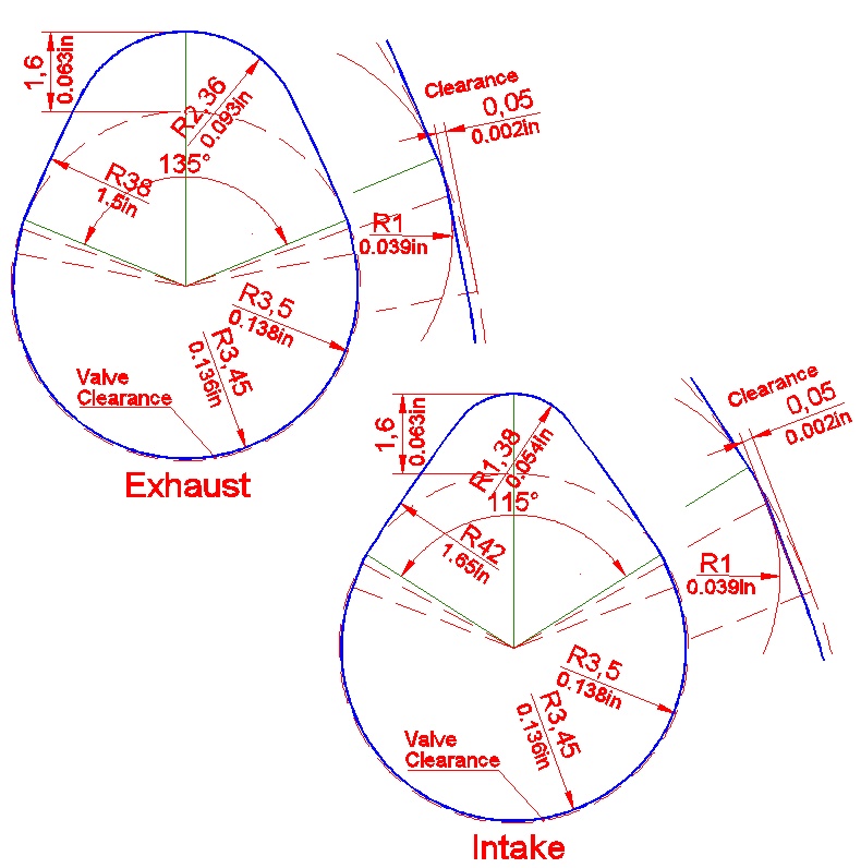
They are still three radius profiles and could be manufactured with all the standard milling and turning methods on soft steal described above as well. But we should have an eye on some valve clearance too. One method to regard the clearance without decreasing the desired action angle is enlarging the manufactured cam angle. But this, when leaving the base circle, will shift the contact point of the follower more or less away from the correct tangential transition which can result in some heavy and unwanted acceleration.
The other method is keeping the original timing angle and giving tappet clearance by undercutting the base circle, it is used for the design of my two example lobes here:
We need a suitable junction from base to flank circle now which can be easily drawn with a transition curve followed by a short tangent leading to the new base circle. The only problem is this little section of our cam profile can not be manufactured with the standard milling procedures listed above.
But as I intend to use my pivoting cam grinder system I only need some simple flat master lobes made from suitable sheet material. Such masters can be milled precisely enough with a standard CNC miller, even a small table top routing machine should do that job (we like to call them cheese mills in Germany
.ha ha ha).
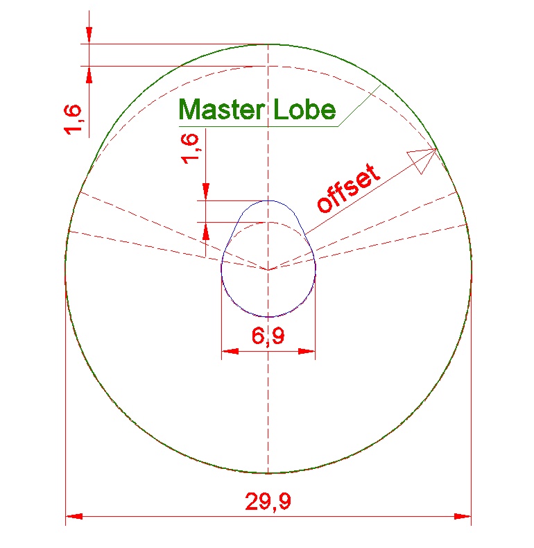
Our cam shafts are no big ones, normally something about 0.3 or perhaps 0.4in of diameter. Larger masters are easier to mill and better to handle on the cam grinder, so I enlarge the masters up to a base circle diameter of 1.2in in general.
This is done with the offset function of the CAD, which leads to some funny shapes. But dont use the varia or zoom function, maybe it looks right to you at first sight, but the grinding results are not usable!
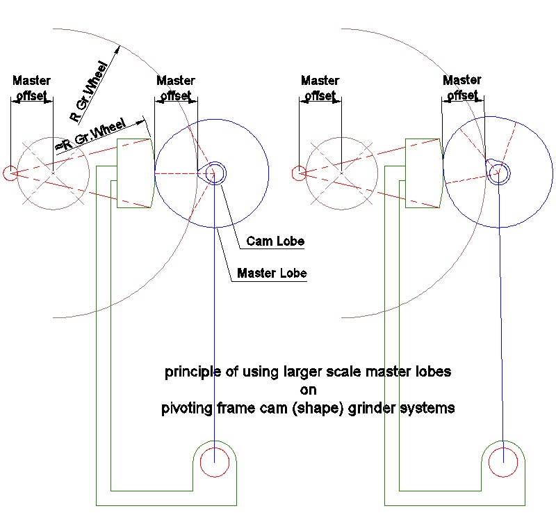
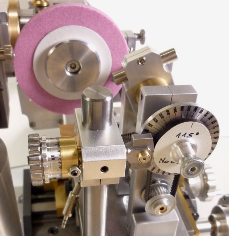
The cam grinder follower system will generate the correct shape from the ugly lobe as you can see on this drawing:
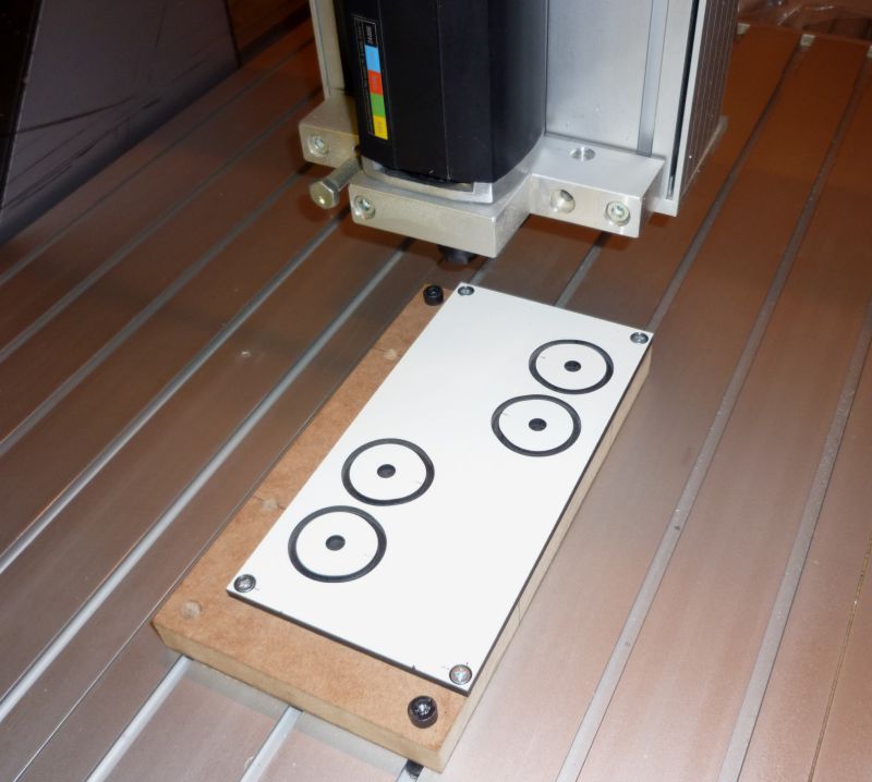
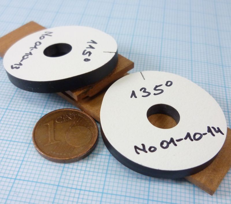
I make the masters from 4mm solid HPL (high pressure laminated) board, this material is easy and precise for milling and it is hard enough for the job on my grinder. But naturally, especially if you want to go on cam shaft mass production, you can take brass or steal sheet as well.
To increase the entertainment value a little bit, two additional videos of the master production
.ha ha ha
.:
http://pl-hi.de/JST/Cam-Grinder/Cam-Grinder_04.mpg
http://pl-hi.de/JST/Cam-Grinder/Cam-Grinder_06.mpg
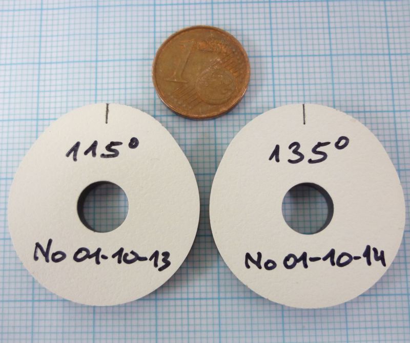
And the finished masters
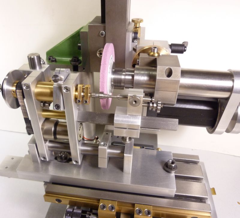
ready to use on my small cam grinder which I already showed here some weeks ago:
Okay, I admit this method requires some sort of CNC machining too, but you only need a standard CNC, no very rare and special machine. I think its a really convenient and fast done process and the results are reliable and precise enough for our needs at all.
Achim