Longboys "SENTINEL" OHC I/C engine.

Home Model Engine Machinist Forum

Help Support Home Model Engine Machinist Forum:

This site may earn a commission from merchant affiliate links, including eBay, Amazon, and others.

Longboy

Well-Known Member
HMEM Supporting Member
Joined
Nov 19, 2009
Messages
813
Reaction score
548
Location
Tucson, AZ
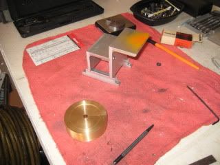
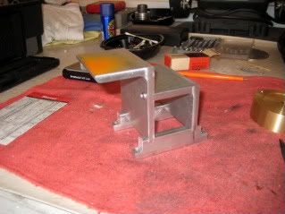
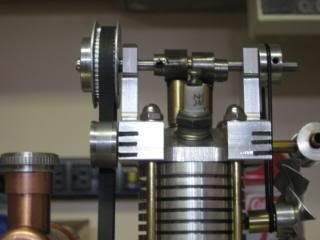
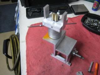
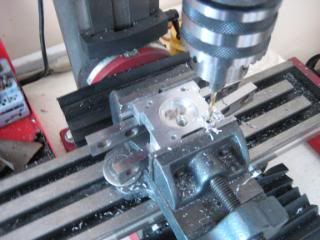
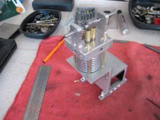
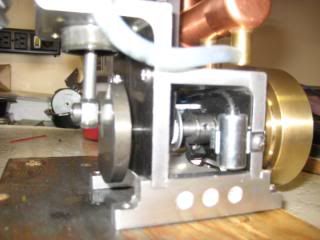
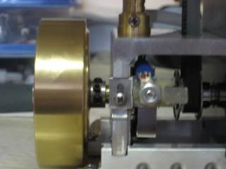
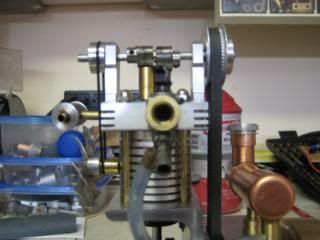
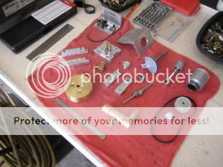
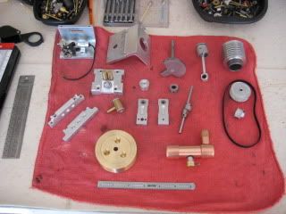
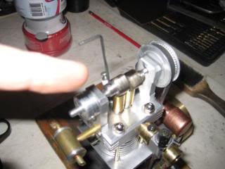
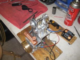
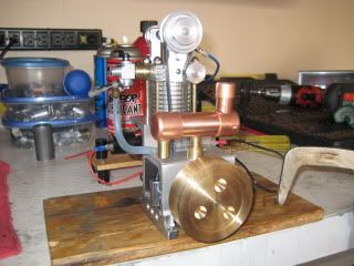
After last winters experience in building the WEBSTER I/C engine from plans I have now explored a scratch build effort. This is the result, something I call the Sentinel. A vertical single OHC engine of 11CC's. Built around a frame of aluminum angle and using the simplified overhanging crank, this engine was a five week program. :) More on the Sentinel over the next few days! Dave.
IMG_0202.jpg
 
Started the Friday before Thanksgiving when my metal order arrived this is somewhere after the 1st week. The concept was to be a vertical engine with an overhanging crank. The frame is a 2x2 and 2x3 aluminum angle 2.25in. long. On the scale is the 12L14 counterweight. It is lightened on one hemisphere by 8/10ths. oz. Ignore the Motorcraft points box, they were not used.
IMG_0167-2.jpg
IMG_0168-2.jpg
 
Starting the cylinder head. A 2 x 2.25 x 5/8in. block being bored for combustion chamber and to accept the cylinder.
IMG_0169.jpg
A horizontal flat is milled into the underside of the head as its being held at the sparkplug angle. Center drilled, thru drilled and tapped for the plug.
IMG_0171.jpg
The topside of head at the sparkplug was milled away 90deg. to plug angle to clear a socket wrench and the CM-6 sparky install is done!
IMG_0172.jpg
 
Drilling in-line for 2 brass valve guides. The guides are epoxied into the head. Valves are made from a grade 5 5/16 hardware bolt (see WEBSTER build). Ports are then lined up from the head perimeter and drilled into head and guide.
IMG_0175.jpg
Valve stems are threaded 6-32 and a brass bucket encloses the valve spring and is threaded to the stem. Valve springs are Ace hardware. Some diamond paste 8) and homemade lapping tool insure a mating surface with the valve seat.
IMG_0193.jpg
 
This is right up my street. Thanks for posting. I'm looking forward to seeing more on this.
 
....thanks Andy. Sentinel is a beginner class engine. Nice to see all the multi cylinder models, the CNC weoponry and the 30 years experiance behind them. Guys like you and me get a fair break on HMEM cause we are all making heirlooms, gleaning skills and progressing our spare time in metal to a satisfactory outcome regardless of our abilitys. :) Dave.
 
The valve assembly in the head completed, ports are drilled and the cam tower blanks located. A pair of cam lobes on the stub.
IMG_0178.jpg
The cam lobes are made with hubs that takes a set screw to lock them into position on the camshaft. The cam cog is not slotted for advancing or retarding the valve timing. Essentially the Sentinel has the same adjustment to cam timing as a DOHC engine does as the intake and exhaust valve action can be located independent of each other, all on one shaft now. I don't know if on a high RPM engine with heavier valvesprings if the setscrews would hold the lobes to its shaft but works fine in this light duty runner.
IMG_0247.jpg
IMG_0237.jpg
The cogs are "MXL" pitch size. 25/50 tooth with a .250 belt the appropriate length. Some venders on the web have a calculator for belt length once you determine the center distance from your drive to driven shafts to the size cogs you would order. The cost is about the same as a pair of gears for a OHV engine. MXL and XL pitch would look size wise correct for model engines up to about 2 in. bore. Hard to tell in the catalogue but go by cog diameters in the chart listings. A .375 width belt would fit my cogs. XL pitch is next size up and also metric dimensioned cogs available. :eek:
 
I was wondering when you were going to post about this...I have been watching your photobucket images. Very nicely done and looking forward to your posts. :bow:
 
Very interesting and nice looking engine. Looking forward to following this thread.

Chuck
 
An early mock-up and fastening of the cylinder with head to frame. Four brass studs threaded 8-32 secure the assembly. Stud holes are located and drilled into head. The cylinder without its radiator inserted into the combustion chamber and dropped into the cylinder cutout in the horizontal leg of the 2x3 angle was used to to square up the location of the studs into the frame. A transfer punch in the stud holes of cyl. head used here.
IMG_0176.jpg
IMG_0186.jpg
Cam towers complete and sculpted. With the cylinder assembly now fastened to the frame, I now have the center to center distance of the crank to camshaft and can now order the cogs and belt. With no plans/ prints to follow this had to wait till I got to this point.
IMG_0187.jpg
 
The connecting rod is made in three parts. Separate small end, beam and big end. 1/2 x 1/4in. aluminum stock for the ends and a 1/4in. round for the beam. The beam is thru drilled ( weight save) :)....threaded 6-32 each end to receive a 1/2 in. long section of SS threaded rod for each end (heavy again) :( ...to tie pieces together as one. The big end/beam is chucked up in the lathe and some #400grit paper dragged across makes the butt seam totally disappear. Adding washers at the small end beam, you can experiment with increased compression now! :eek: I started with 3 washers (.096) upon completion. Piston is WEBSTER plan with O-ring. Piston/rod assembly weighs 1.3ozs including the big end shoulder bolt to counterweight.
IMG_0188.jpg
IMG_0195.jpg
IMG_0194.jpg
 
Originally I was going to use automotive point set outboard behind the flywheel. A trip to ACE for a look/see at some small engine tune-up kits allowed me to put the points inboard. Note the Tecumseh points set has a condenser about half the size!
IMG_0231.jpg
A bracket fabricated for the spring and insulated block of points was not quite located for mounting. The spring kept the points open. Slotting and raising its position reverted the spring to points normally closed position then. With inboard ignition the flywheel is about 1/2 inch closer to frame now, a better overall appearance. :)
IMG_0236.jpg
 
The surface behind the counterweight is not painted. Some 3M vinyl in dark charcoal is overlayed here and the inside area of the frame. Available at sign shops and auto supply it offers an alternative for those who wish to color some flat surfaces of their projects.
IMG_0234.jpg
The copper fuel tank is on board the deck and feeds a R/C engine carb. This particular carb ordered from EBAY doesn't have a needle jet to the throttle arm and therefor doesn't throttle up more than two hundred RPM before stalling. Sentinel runs for 20 minutes per filling. The cooling fan is 2in diameter driven at engine speed.
IMG_0230.jpg
 
Most of the parts finished for assembly here. I'm close to the big day! :)
IMG_0197.jpg
IMG_0198.jpg
Setting cam timing using the counterweight as a basic degree wheel.
IMG_0226.jpg
On the test bed! December 27th. running. ;D
IMG_0201.jpg
Ah YES, running!........I remember that time back in the winter of '84 when my girlfriend and I were running........(ENOUGH LONGBOY! :rant: ...YOU BETTER COME UP WITH THE VIDEO.....OR ELSE! th_rulze) hUH? OH, ok HERE IT IS! [ame]http://www.youtube.com/watch?v=zmY8QS6w1mU[/ame]
 
Outstanding, you have inspired me. :idea:
Sounds great too.
 
Nice Dave, a good runner. Innovative. Enjoyed the ride. :bow:

Regards,
Rudy
 
Good one! Thm: Got a nice, gutsy beat!
 
You have got a real winner, Dave.
Thanks for sharing.
Gail in NM
 
Great sound Longboy, and a steady runner too like an old BSA :). can you tell me what takes the thrust from the cams, I don't see any tappets, does your engine rely on the generous sized guides you have used?
Stew
 
Back
Top