LONGBOY'S "JUSTABLE" MODEL GAS ENGINE!

Home Model Engine Machinist Forum

Help Support Home Model Engine Machinist Forum:

This site may earn a commission from merchant affiliate links, including eBay, Amazon, and others.

Longboy

Well-Known Member
HMEM Supporting Member
Joined
Nov 19, 2009
Messages
811
Reaction score
546
Location
Tucson, AZ
I got a phone call last month from "Bob Thomson" over at "NOR'WESTERN LOGISTICS"' They are a maintenance and infrastructure support company for the mining, lumber and oil industries and service U.S. and Canadian firms. He tells me that the little single, "Sentinel" engine I developed for them in 2010 was just ideal for their purposes. Durability, low service intervals and all weather performance. Asked if I would be interested in creating another with a greater capacity. Since I was wrapping up my build of the "Side Shafter" engine........I could most likely have a presentation built before Labor Day.

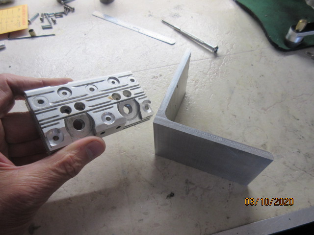
Starting soon, The Longboy "Justable" engine!

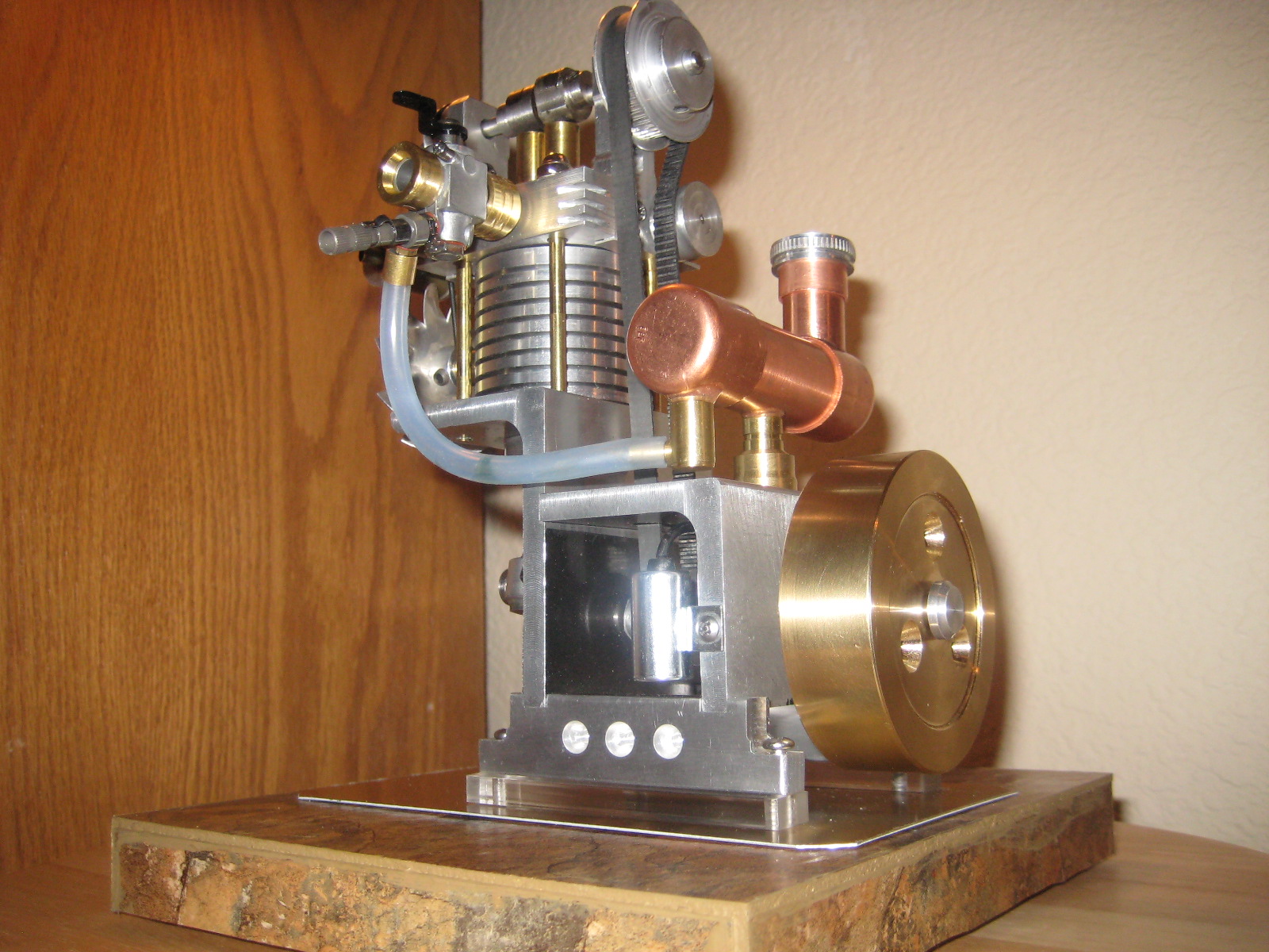
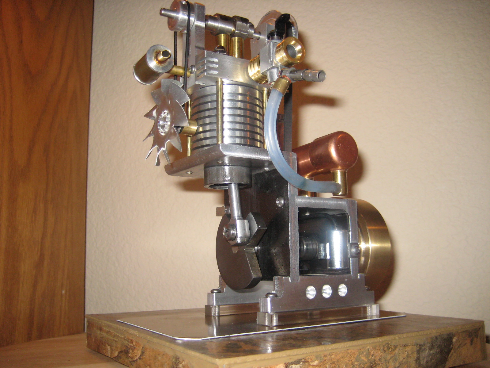
The Sentinel engine (2011)
dpOJ0Oc.jpg


hGkHQ2o.jpg
 
Last edited:
The beginnings of JUSTABLE start with these two pieces. The 2 inch bore centerline cylinder head is a leftover from my first 2 cyl. engine, "GEMINI". I couldn't get a center bearing to work by getting a proper line up of 3 bearings at the time. I duplicated a shorter cylinder head with 1.5 in bore centers and reworked a 2 bearing crankshaft and let a single long throw pin carry both con rods for that engine. Let the normal evolution of skill development take place in this hobby on later models.
u0QwaM6.jpg

On this head, the outboard holes for the head bolts are at 3.75 in. centers. The angle aluminum, left over from SIDE SHAFTER just completed, is 4 in. ! Now I can use this head on a project! With some .25 in. stanchions to mount the head to the deck, I have....." just enough room".....to mate these items and save a few days making another head! :)
 
Last edited:
JUSTABLE gets a three piece set of crankshaft webs.
zIbTtHN.jpg


7hMMu3w.jpg


And the finished segments. There is one throw pin.....but three webs! Is JUSTABLE a single cylinder....or a twin? Either way, are there the right number of crank parts here for a one or two cylinder engine....or too many, too few? :rolleyes: I'll let the forum play around with that question before the next posting.........
ZrLib80.jpg
 
I'm trying out a hole saw on the deck for the cylinders, my original method before I bought a boring bar kit for the mill. Slow going with lube, the mini mill breaks circuit often if too much feed on one inch dia. and greater tools. Finished up with a basic China Special bore tool.
II24Oqr.jpg

Zf09NQw.jpg

Barrel shape pistons with multi piece con rods tuck into the bores. Note the difference in the rod big ends between the two.
vRZtEUh.jpg

The camera's view alludes to a pair of over sized radiators upon the cylinder deck..... however they fit within the cyl. deck perimeter to bolt on the cyl. head. I had......"just enough room" to make it so.
ogmidi2.png
 
Last edited:
I assume from the title of the thread that there is something adjustable on "justable". What is it?---Brian
 
Thanks Brian. There is nothing adjustable beyond a spark plug gap, ignition advance, carb needle setting or valve lash clearance. JUSTABLE's creation results from a series of circumstance around some leftover pieces that may never have come together due to tight spacing of its components.
 
Last edited:
Underneath the short angle frame piece goes the Tecumseh points. My favorite for their versatility mounting in tight quarters. The crankshaft offset from center of piece leaves little room on the outboard side to place them. Well.....I was "just able" to do such as you see. A ball hex wrench and 4-40 socket head substitute will allow access to adjust the gap easily.
yJd06Nd.jpg


A sample crankshaft stub with the points cam trigger through the bearing gives me an idea where the pivot point will be when the cam hits the rub block.
R7jY4QR.jpg


The spring and stud insulator stick out from the frame. The insulator will slot into a thin piece of hardware store angle aluminum and will make for easy connection with the ign.coil. Bolts up to the backside of frame tucked next to the bearing carrier.
c2D135v.jpg


One other component goes onto the crankshaft, the cam drive. GOLLY! ...it "just made it"! ;)
v7kN6GW.jpg
 
I'm trying out and sticking with a new material for the valves.
foDaKt7.jpg


From SPEEDY METALS with a full line of diameters of 12L14 steel rounds. Ordered some valve material as well as flywheel rounds at 3.75 and 4.0 inch dia. I'd say an easier cut than SS. No galling or chunking and a clean finish with no follow up treatment in the seat area of valve.
eKKD8OF.jpg

QiV5sDs.jpg


As for flywheels. Still a chore. Slow going removing metal from large diameter stock on the mini lathe. :confused:
 
I'm trying out and sticking with a new material for the valves.


From SPEEDY METALS with a full line of diameters of 12L14 steel rounds. Ordered some valve material as well as flywheel rounds at 3.75 and 4.0 inch dia. I'd say an easier cut than SS. No galling or chunking and a clean finish with no follow up treatment in the seat area of valve.

I've never contemplated using 12L14 for valves as I'd be afraid of how quickly the stuff likes to rust. It'll be interesting to see if it causes you any troubles. I agree it's nice stuff to machine though.
 
I've never contemplated using 12L14 for valves as I'd be afraid of how quickly the stuff likes to rust. It'll be interesting to see if it causes you any troubles............
Thanks Cogsy. The fuel mix with WD-40 plus the combustion carbon coat has both valves "covered" for corrosion intrusion. For wet sump splash models, a dribble down the valve stem of lube should cover the top end for long term storage. I have flywheels in unpainted C.I. and steel as large external parts with no rust.........that's just indoor display conditions and you will be all right using steels for model parts fabrication!
 
Last edited:
Dave, it sounds like this might be the first time you have used 12L14? Yes, it machines like a dream; that's exactly what it is made for, with both sulphur and lead added to the alloy for just that purpose.

As Cogsy notes, however, it also rusts in a half-second, far, far more quickly than cast iron or 1018 or similar mild steel. And, just in case it ever comes up, it is not recommended for any sort of welding, as in, it will bubble up with all sorts of porosity if you try.

As you point out, the lubricant-rich environment may make its tendency to rust a moot point ...
 
Dave, it sounds like this might be the first time you have used 12L14? Yes, it machines like a dream; that's exactly what it is made for, with both sulphur and lead added to the alloy for just that purpose.
...................As you point out, the lubricant-rich environment may make its tendency to rust a moot point ...
Thanks awake. I learned about 12L14 steel with it's lead content somewhere along in the forum years back and have been using this grade steel for crankshaft webs in 1.75- 2 inch diameter. Maybe the steel barons heard the call from hobby machinists to come up with this alloy! :) Since crank webs are the only steel parts of size in my models that need cutting, drilling, thread tap and facing, I appreciate the difference in easy of working, especially on my tabletop machine tools which are a hair underweight working C.R. Now trying 12L14 for the same reason with flywheels and the clean cut needed for valve faces. The webs get steady droplets of oil from the bottom of the cylinders post combustion.
 
Last edited:
The lower deck piece is 2 x 2.25 in. surface. I need two items upon it, the cam drive and a distributor.
RQcXEYN.png


The cam sprocket location is the difficulty here.
UrAowYk.png

I measure for an approximate position for the camshaft bushing through the vertical leg of the cylinder deck, go to my belt length calculator ( Timing Belt Calculator - Belt Length Calculator | B&B Manufacturing) and order a MLX 81 tooth. The arc in the upper left corner is my margin of position. It is a 2 inch center line, crank to camshaft.
If the belt is low to the left......I am running the lifters too close to the edge, right off the upper deck and with the belt upon its sprocket, the belt slot will be beyond the left edge of lower deck.
If I follow the arc up and to the right, I'm running the cam lobes right into the underside of the upper deck. Had to sit and think about this for awhile........and I got a solution! :)
 
Thanks awake. I learned about 12L14 steel with it's lead content somewhere along in the forum years back ...

It's the Goldilocks problem of any on-line forum, especially for a relative newcomer like myself - am I assuming too little, too much, or just right? Fortunately, you were much more gracious than Papa Bear even though I told you something you already knew. :)
 

Latest posts

Back
Top