I started this thread over on Madmodder.net, and will copy the build posts over to HMEM. This is my second engine in 2 months of building them socomments are welcome...
Now that I have put the Webster to rest, I am starting on the Otto from Jan Ridders plans. What a great guy! I have emailed back and forth with him and he has given me some good insight in his design process and reasoning. The plans arrived in my GMail box a few days ago, so off I go...
http://www.ridders.nu/Webpaginas/pagina_otto_viertactmotor/otto_frametekst_engels.htm
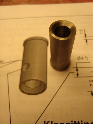
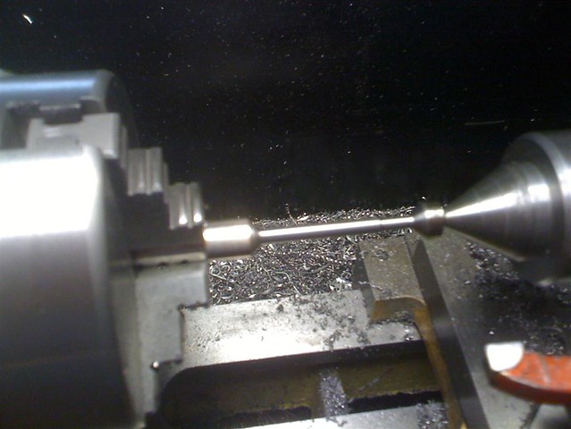
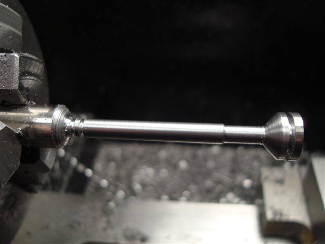
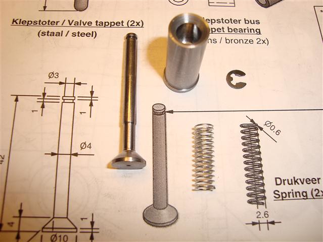
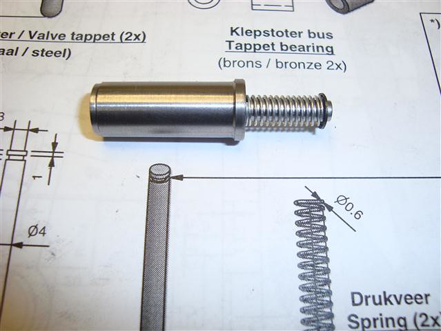
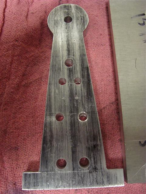
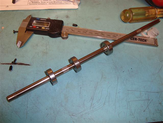
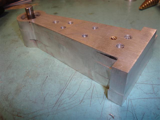
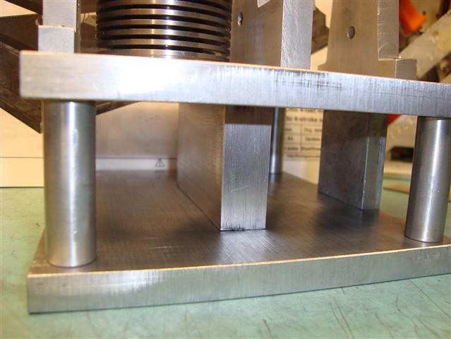
So far I have the cylinder, piston, and head cut and I am beginning to work on the valves... Afterword I will start on the uprights, shafts and 2 base plates. I have not decided on the fuel or ignition at this point, both can be determined after completion of the main engine. I have had very good success with the vapor carb, so I will probably go that route. For the ignition I am looking into the setup on the cheap little Chinese pocket bikes. It is a CDI system that you can get all the parts for for around $20 US.
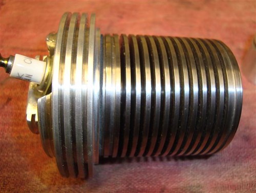
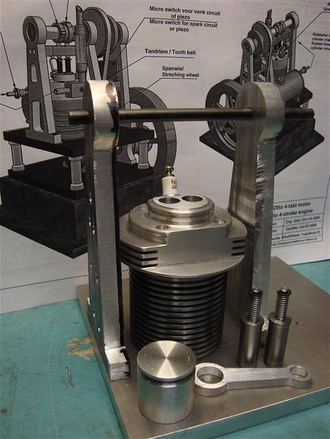
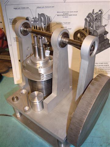
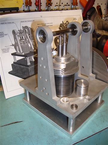
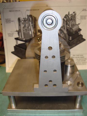
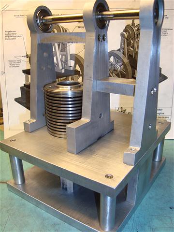
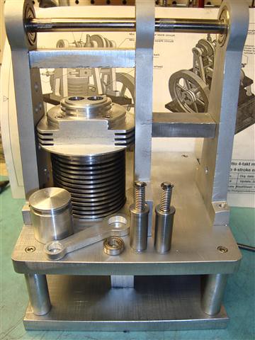
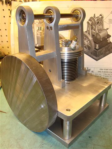
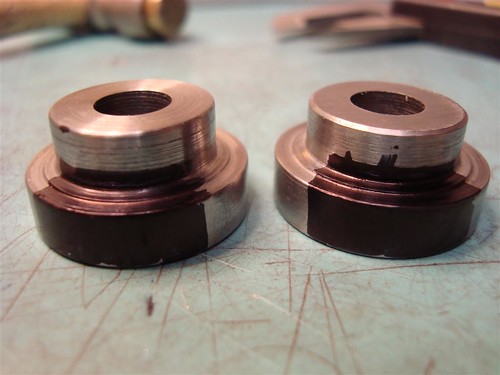
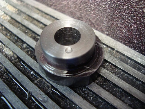
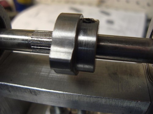
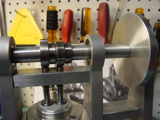
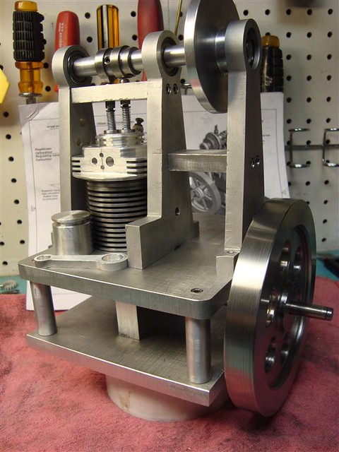
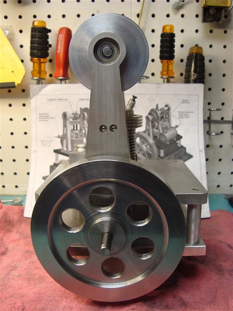
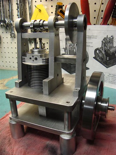
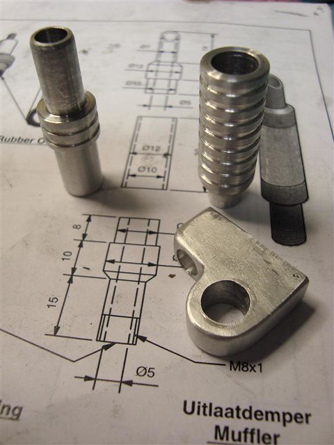
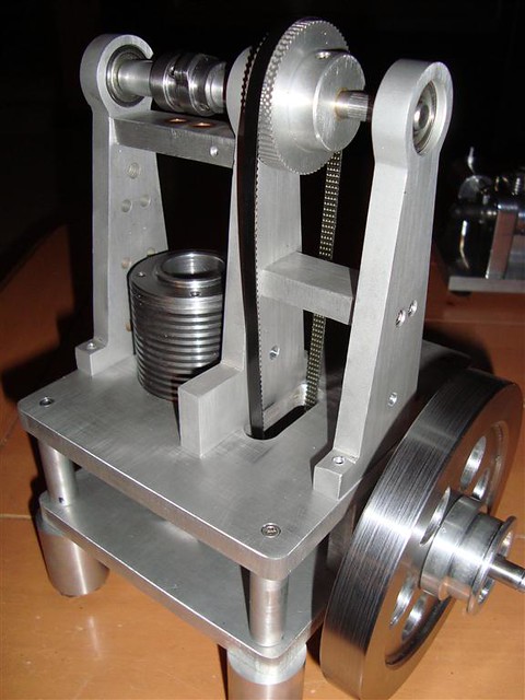
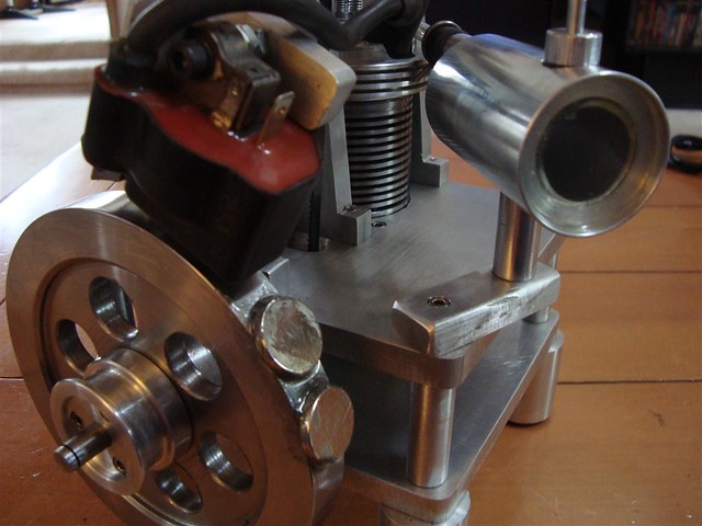
Here is what I have so far: (I have altered Jans plans a bit by adding some cooling fins to the head and more fins to the cylinder)
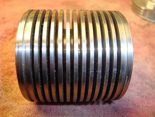
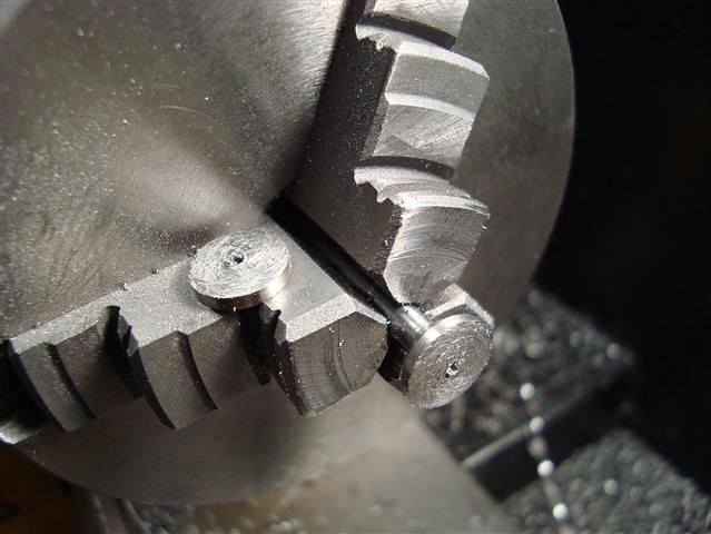
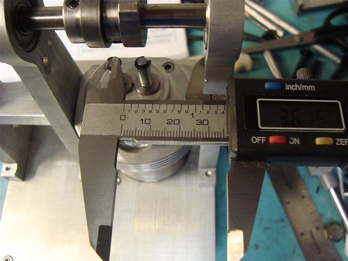
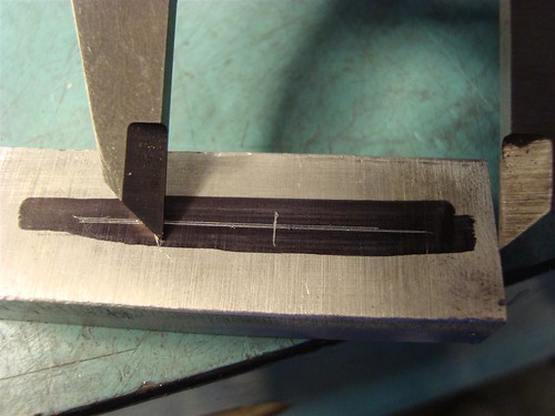
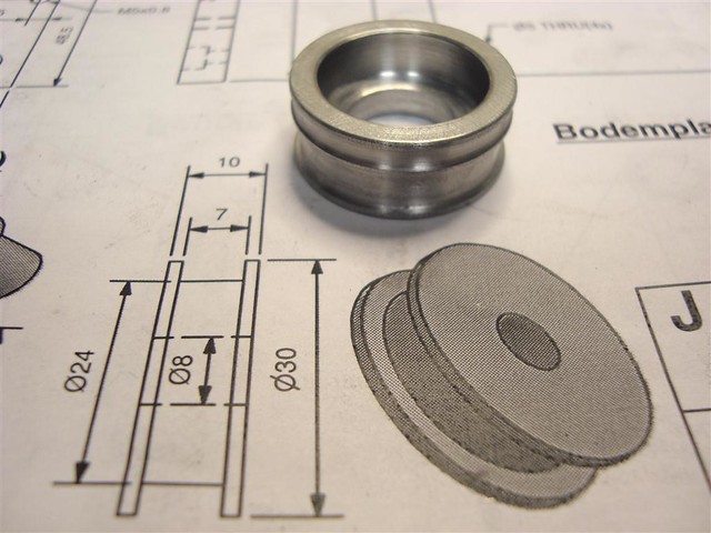
The Cylinder is 2 inch x 2 inch 12L14 steel that I bored out (have not honed) and then I cut the fins with a 1/16 inch cut off tool skipping every thread on my lead screw. Worked really good until it snagged one time and stopped dead, thus breaking 3 teeth off the PLASTIC two speed transmission gears in the spindle (cheap Chinese lathe...) I have since replaced the gears with metal ones from LMS and do not plan on having to do that again. (one downside is that they are a bit noisy, but I hope that will wear in after running for a while...)
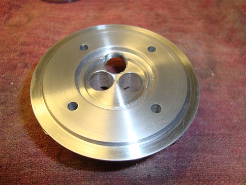
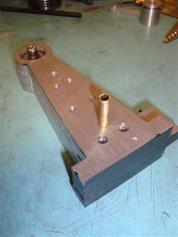
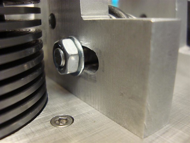
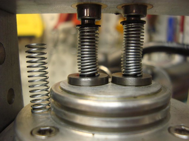
I tapped the head bolt holes to 6-32 for some stainless socket heads. I think they look better.
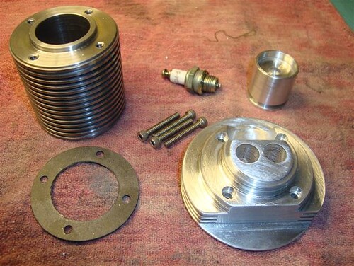
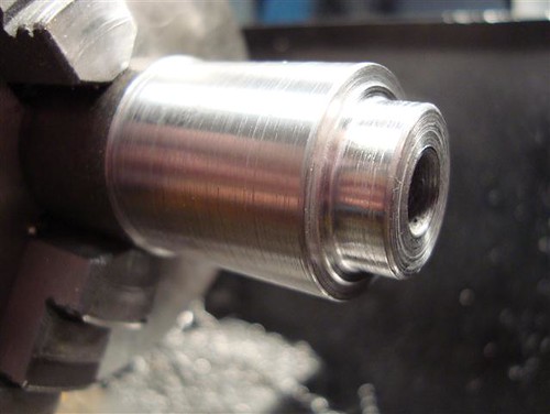
The head is 6061 T6 and is close to spec other than the fins and I am using an NGK CM-6 instead of making my own plug. I like to limit the points of failure as much as possible, these plugs should last 1000 times the life of the engine.
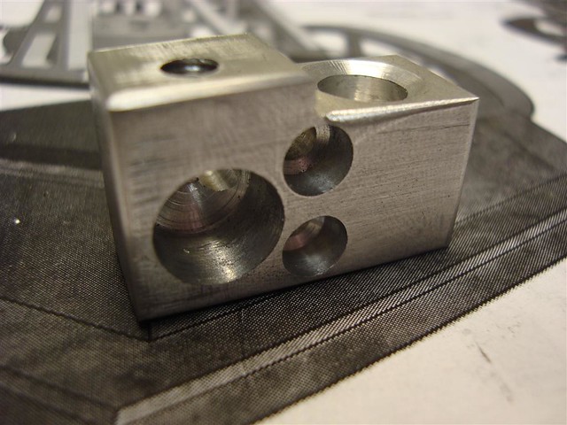
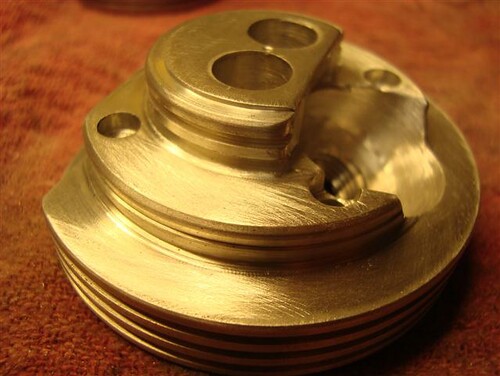
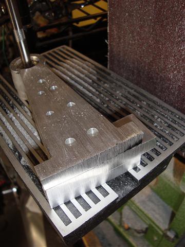
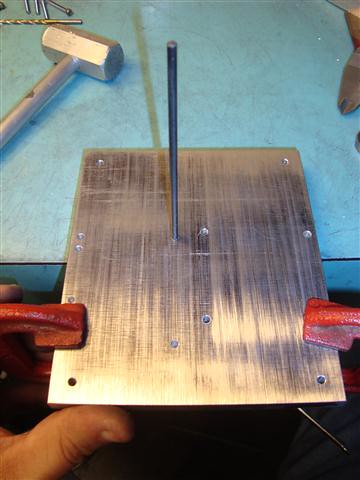
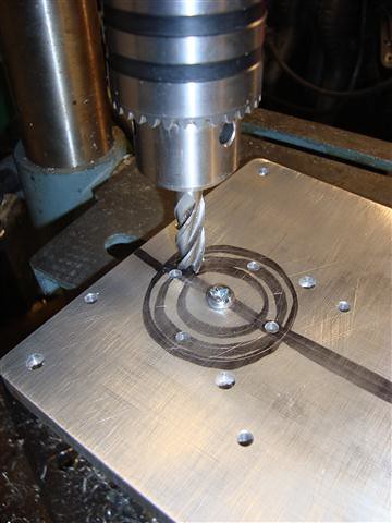
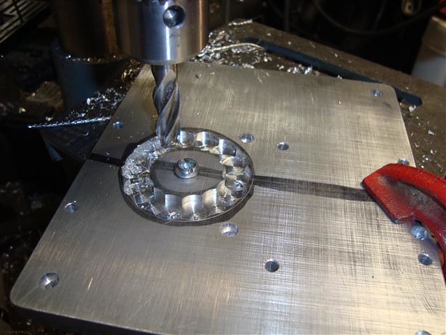
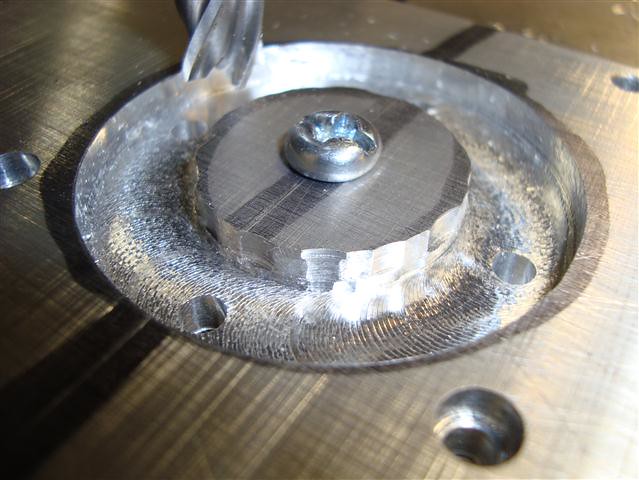
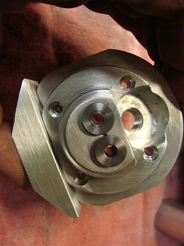
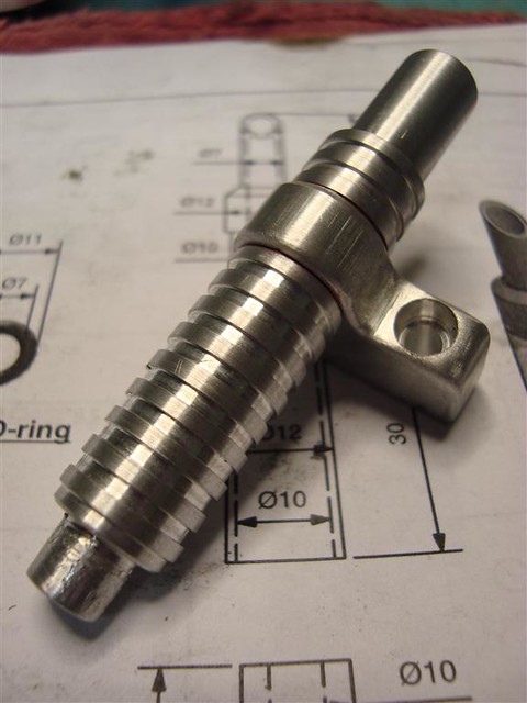
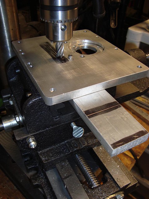
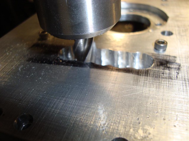
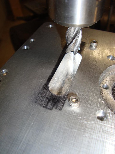
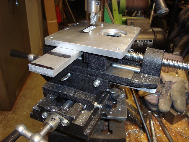
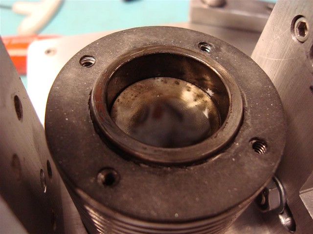
The underside of the head. The angle of the plug was changed to 20 degrees and could have been 25 for the shorter CM-6 NGK plug. Without a true mill, I had to use my poor mans mill and then clean it up with my dremel. The seat got a little wide and cut into the valve guide holes, but you will never see it when the guides are pressed in and the plug is capped.
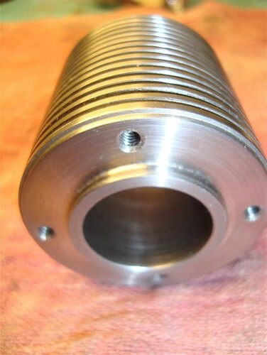
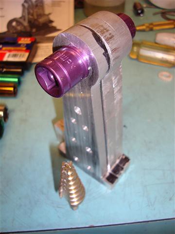
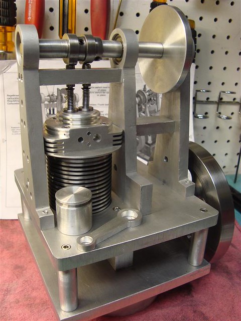
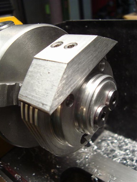
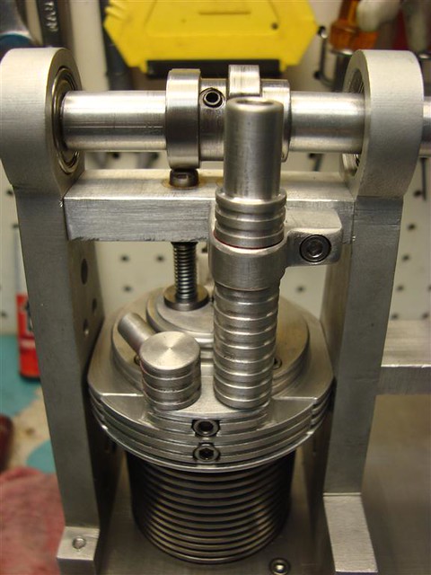
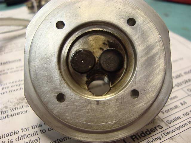
The top of the head. I liked the cooling fins so much I decided to carry them up to the head. It will be functional and look good as well. I will have to cut the side back with my belt sander to clear the uprights.
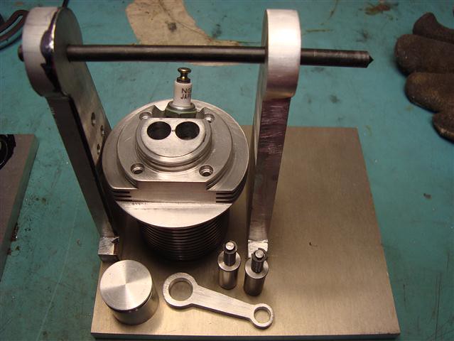
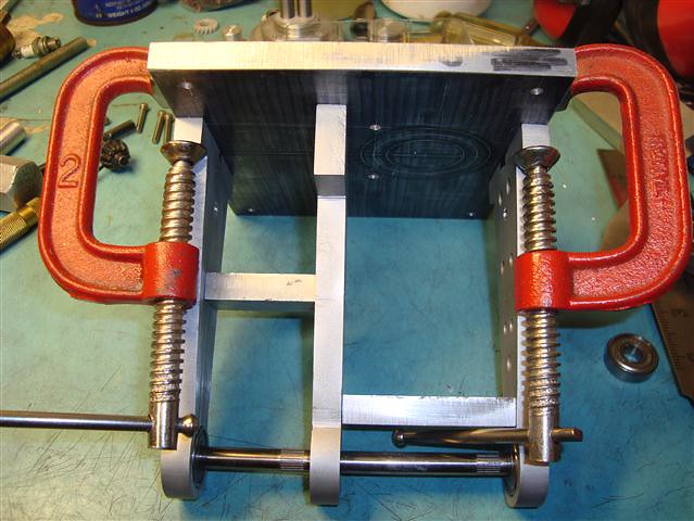
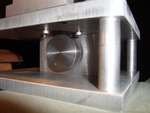
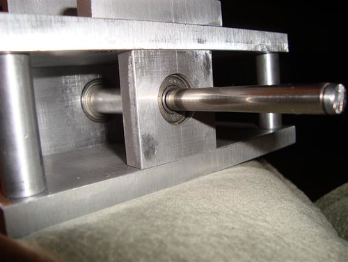
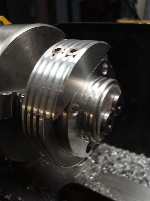
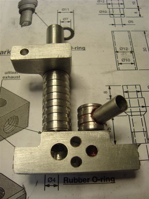
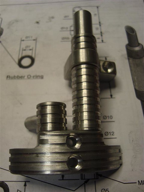
Head and cylinder assembled.
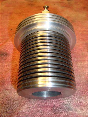
Head and cylinder assembled.
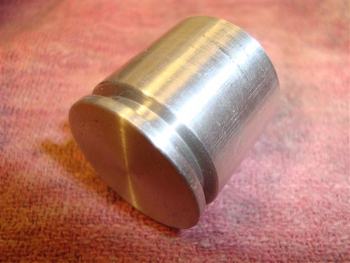
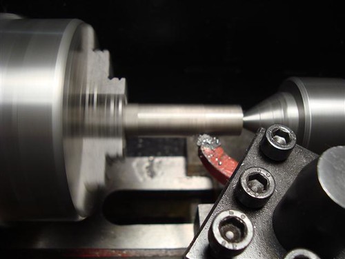
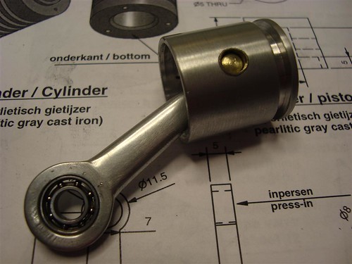
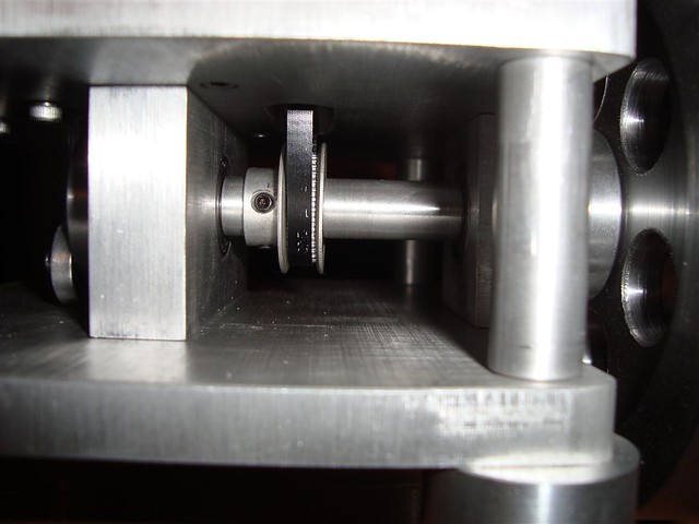
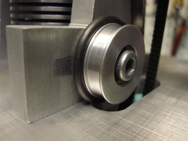
Piston. I am going to use a viton o-ring to seal the piston. This worked VERY well in the Webster and I have a complete set from Harbor Freight.
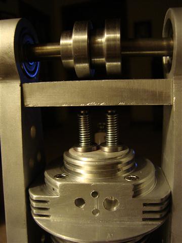
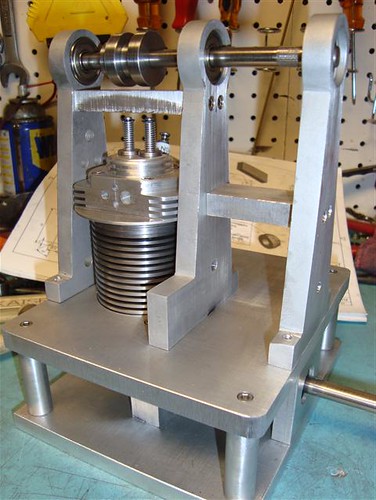
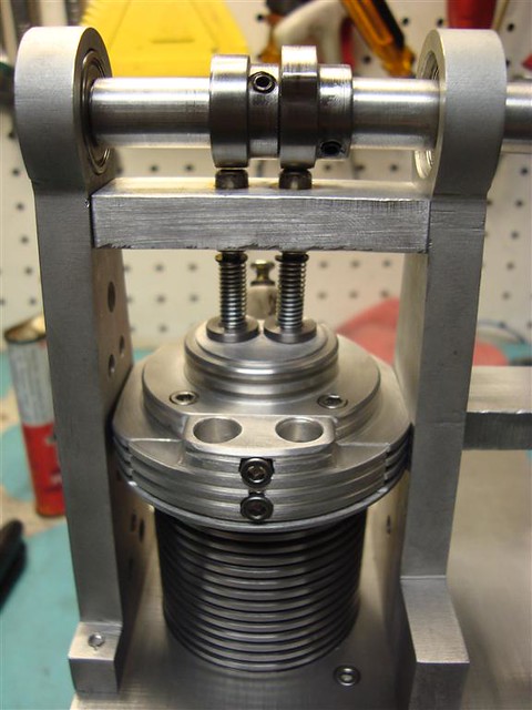
more to come......
Now that I have put the Webster to rest, I am starting on the Otto from Jan Ridders plans. What a great guy! I have emailed back and forth with him and he has given me some good insight in his design process and reasoning. The plans arrived in my GMail box a few days ago, so off I go...
http://www.ridders.nu/Webpaginas/pagina_otto_viertactmotor/otto_frametekst_engels.htm
So far I have the cylinder, piston, and head cut and I am beginning to work on the valves... Afterword I will start on the uprights, shafts and 2 base plates. I have not decided on the fuel or ignition at this point, both can be determined after completion of the main engine. I have had very good success with the vapor carb, so I will probably go that route. For the ignition I am looking into the setup on the cheap little Chinese pocket bikes. It is a CDI system that you can get all the parts for for around $20 US.
Here is what I have so far: (I have altered Jans plans a bit by adding some cooling fins to the head and more fins to the cylinder)
The Cylinder is 2 inch x 2 inch 12L14 steel that I bored out (have not honed) and then I cut the fins with a 1/16 inch cut off tool skipping every thread on my lead screw. Worked really good until it snagged one time and stopped dead, thus breaking 3 teeth off the PLASTIC two speed transmission gears in the spindle (cheap Chinese lathe...) I have since replaced the gears with metal ones from LMS and do not plan on having to do that again. (one downside is that they are a bit noisy, but I hope that will wear in after running for a while...)
I tapped the head bolt holes to 6-32 for some stainless socket heads. I think they look better.
The head is 6061 T6 and is close to spec other than the fins and I am using an NGK CM-6 instead of making my own plug. I like to limit the points of failure as much as possible, these plugs should last 1000 times the life of the engine.
The underside of the head. The angle of the plug was changed to 20 degrees and could have been 25 for the shorter CM-6 NGK plug. Without a true mill, I had to use my poor mans mill and then clean it up with my dremel. The seat got a little wide and cut into the valve guide holes, but you will never see it when the guides are pressed in and the plug is capped.
The top of the head. I liked the cooling fins so much I decided to carry them up to the head. It will be functional and look good as well. I will have to cut the side back with my belt sander to clear the uprights.
Head and cylinder assembled.
Head and cylinder assembled.
Piston. I am going to use a viton o-ring to seal the piston. This worked VERY well in the Webster and I have a complete set from Harbor Freight.
more to come......
")