Is it called "line boring"

Home Model Engine Machinist Forum

Help Support Home Model Engine Machinist Forum:

This site may earn a commission from merchant affiliate links, including eBay, Amazon, and others.

Lew Hartswick

Well-Known Member
Joined
Sep 20, 2007
Messages
505
Reaction score
10
Whatever you call it. The boring bar between the spindle and the tail stock.
I've never seen this done but an application came up at school today (at least I think).
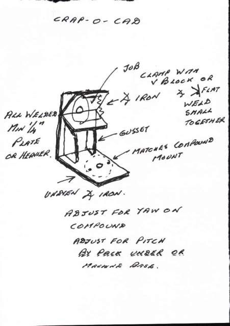
The BIG question Was/is how to hold the work and even more important how to
align the piece in the vertical direction and the pitch yaw degrees of freedom.
If anyone has a few pictures of mounting an object to do this I'd sure like to see them.
I can picture some sort of bull nose centers in the tail stock and maybe another in
the chuck to get the axis aligned but how in the world to then "grab" the work to do
the boring is beyond me at the present. As another part of this, advancing the cutter
in the required small increments may be a little tricky also.
Thanks for any pointers.
...lew...
 
Lew,

If you don't have a Tee slotted cross slide then I would recommend you fabricate a holding bracket for use with a 4 point tool post which rests on the cross slide - last resort drill and tap the top of the cross slide.

For the boring bar fine adjustment can be achieved by making the hole for the tool bit on an angle and only half way through the bar. The other half of the hole for the tool bit is tapped to take a grub screw which screws down on the end of the bit allowing it to be advanced in very small increments. Finally there is another grub screw cross drilled into the bar to lock the tool bit in place.

Alignment of the work can be done by scribing a line on the outside and adjusting to this line for pitch and yaw.

Hope this helps and you can follow what I'm on about.

Best Regards
Bob
 
Thanks Bob I have that idea for adjustment of cutter now. Can see how that would
work fine. As to the cross slide here are a couple pix with and without the compound.

Crossslidewithcompound.jpg


withcompoundremoved.jpg


The piece under discussion at the moment is a chunk of pipe about 7" long and about
2 1/2 diameter ( at least less than 3") and how to hold it in the right place. I guess
if it is serious enough an angle plate that mounts on the post that the compound
uses will be the way but making it adjustable in the vert. and angle in the pitch
direction will be the trick.
Some more thinking is in order. :)
...lew...
 
Lew,

Below is my crap o cad bracket.

Bracket.jpg


To get close to the alignment, use the boring bar between centres, (or any parallel lump), to hold the angle iron against the unven upright, with the uneven bolted in place on the compound. Cover any exposed slides, chucks, bits you don't want spattered and tack the 2 Angles together. Remove, weld up and add gussets.

At least it is a start if not the ants pants solution.

Hoping it gives food for thought.

Best Regards
Bob
 
AH! so. Thanks for that Bob. I get it now. Obviously once it is built all the parts
will be at the same height. So only if the object is an irregular shape would it
require a vert. adjustment. I "don't do welding" but can be depended on to do a
lot of unusual bolted constructs. :) And if the V holder is a removable part it could
be changed to some other shape for future applications. I have a large cast iron
angle that was part of an optical instrument that should work for the base part.
Tomorrow will see what develops. :)
...lew...
 
The easiest way to get adjustment in the vertical plane is to mount the work on a vertical slide, I've done this a number of times but don't have any pictures. Could mock something up if you want a picture.

Jason
 

Latest posts

Back
Top