Howell v-2 four stroke gas engine.

Home Model Engine Machinist Forum

Help Support Home Model Engine Machinist Forum:

This site may earn a commission from merchant affiliate links, including eBay, Amazon, and others.
Gus--I have found that with valve guides it is better to not put the valve seat in them until they are pressed/loctited into place in the cylinder head. That is because the guides can deform if the pressing in requires much force, the guides will go out of round. I generally press/loctite the guides into place, then use my Geo Britnell tool to put the valve seat in by hand, then lap the valves into the seats "in place'. I get more consistant results that way.---Brian


Hi Brian,

Thanks for the timely alert advice. I did get deformed valve seats with earlier engines. Pressed in guides did get deformed with very tight fits.Spent too much time lapping and lapping and lapping. Taking my sweet time enjoying making the small and vital parts.The V-2 Carb will be very challenging.Will loctite in the guides tomorrow. Lapping will be done very much later.Sure hate to get lapped tappet valves mixed up and mismatched.
This was learnt from previous engines.:hDe:
Gus now reformed machinist and engine builder. Best to study/scrutinise/comprehend every drawing and write up work procedures and also ensure I have the right tools for the right job and if not DIY them. The odd size counterbores were good examples.
Trust warm weather coming your way. Meanwhile we are having a dry spell which means no rain and good fishing.
 
another thanks! I was going to cut the seats with the valve guides on the lathe and then press them in but I guess I'll change my tactic and plan on making a seat cutter. Would it be safe to thin the seat on the lathe (cut the angle on the face, and angle in the throat, of a 3 angle seat), but don't cut the 45 degree angle seat that contacts the valve seat until it's installed? That would mean you'd only have to make 1 valve seat cutter instead of 3.
 
another thanks! I was going to cut the seats with the valve guides on the lathe and then press them in but I guess I'll change my tactic and plan on making a seat cutter. Would it be safe to thin the seat on the lathe (cut the angle on the face, and angle in the throat, of a 3 angle seat), but don't cut the 45 degree angle seat that contacts the valve seat until it's installed? That would mean you'd only have to make 1 valve seat cutter instead of 3.
No one I know does a 3 angle grind on valve seats meant for a 1/4" or 3/8" diameter valve. There is only one angle involved, and that is the 45 degree angle cut with the George Britnel style valve cutting tool---and that is cut by hand, not under power.
 
No one I know does a 3 angle grind on valve seats meant for a 1/4" or 3/8" diameter valve. There is only one angle involved, and that is the 45 degree angle cut with the George Britnel style valve cutting tool---and that is cut by hand, not under power.

I suppose if you keep that cut shallow enough you avoid making too wide of a seat. Thanks! I'll give that a shot.
 
No one I know does a 3 angle grind on valve seats meant for a 1/4" or 3/8" diameter valve. There is only one angle involved, and that is the 45 degree angle cut with the George Britnel style valve cutting tool---and that is cut by hand, not under power.


Hi Brian,

SOS SOS.

Please e-mail George Britnell Valve Cutter.
 
Day 23.
Exhaust and Intake Ports via Brass Valve Guide.
As I was about to plunge in with standard 6 mm drill bit into the Aluminium O/Head and thru to valve guide,I pulled back. The Brass Valve Guide would snatch/grab/pull drill bit and damage O/Head.Regrind twist drill with modified rake. All four ports safely done.;)

Valve Stem Pin Hole
I have four tappet valves which took 4 hours to make. Recalled I made a drilling jig for this purpose. All 4------2mm pin holes done w/o mishap.:cool: As a precaution, I use brand new quality drills. No cheapy M.I.C. drills.

IMG_3108.jpg


IMG_3106.jpg


IMG_3110.jpg
 
Last edited:
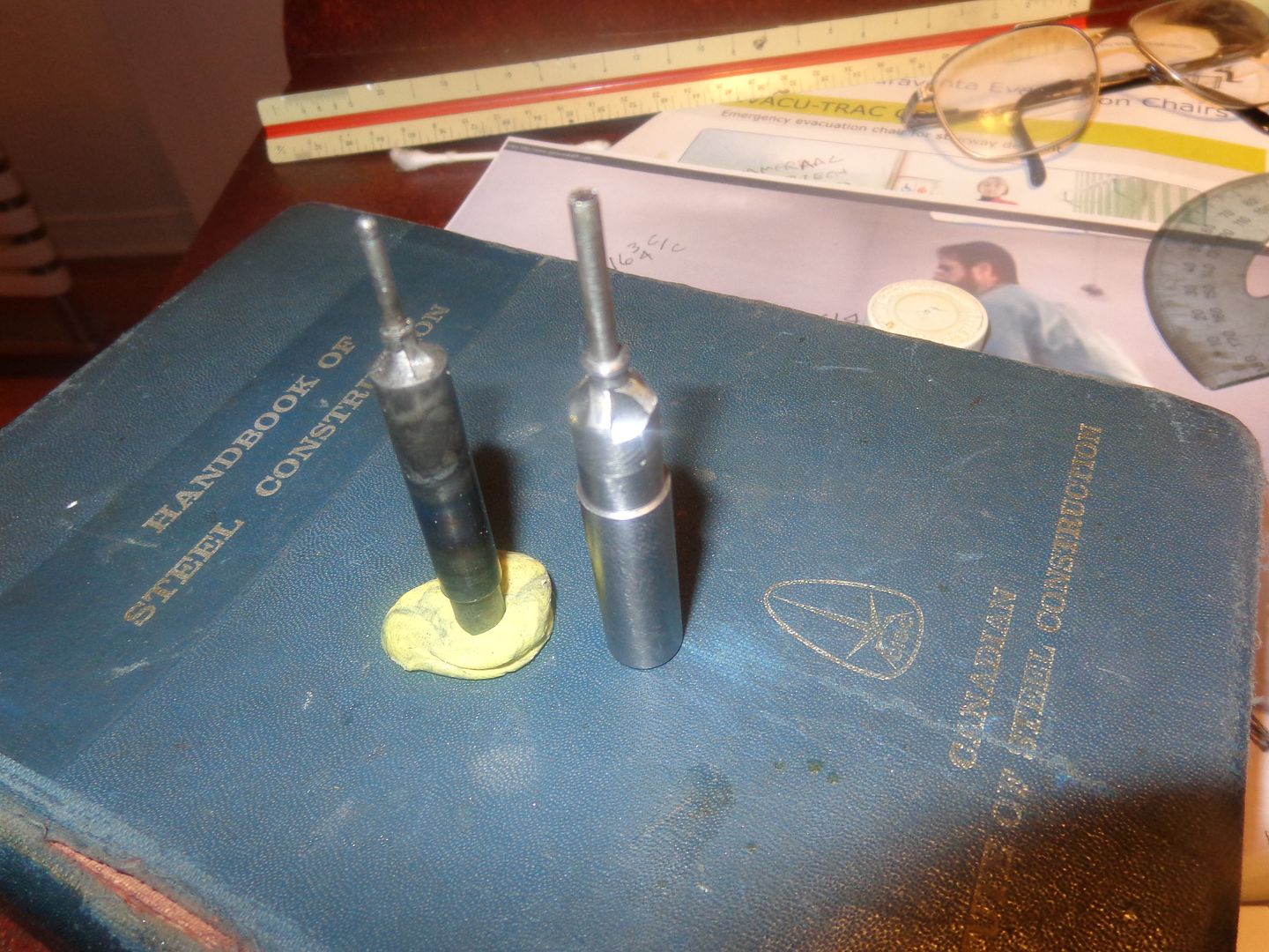
Gus--This is the George Britnell valve seat cutting tool, and it is amazing!! There are a few write ups about it on the website, but I can't find them just now. Material is 01 (oil hardening) or W1 (water hardening) steel. The largest diameter must be larger than the head of your valve and can generally be 1/2" or whatever metric size is considered a "stock" size close to 1/2". the smallest diameter is designed to be a "good sliding fit" through the valve guide. The next larger diameter should be about .020" to .030" less than the hole in the valve cage directly above the valve guide hole. The taper is 45 degrees. The diameter directly above the taper should be about .080" larger in diameter than the maximum diameter of the valve seat. The four facets are cut in by plunge cutting to center with an end mill four places at 90 degrees, then filing a small relief angle running back from each cutting edge. (be sure NOT to hit the cutting edge with the file.) First the valve cages are turned (seats not cut) and press fitted/loctited into the cylinder head. Then the smallest diameter on the tool gets a bit of light oil and is inserted into the hole in the valve cage, untill the 45 degree angle face is resting on the sharp edge of the hole in the valve cage. Now--with a light hand pressure turn the tool through a couple of full turns. This cuts a perfect valve seat every time. The seat should only be .015" to .020" maximum, not more. The tool can be hardened by flame and quench, but if the valve seats you are cutting are brass, it doesn't really need to be hardened.
 
Last edited:
Thanks Brian.

Will DIY Valve Seat Cutting Tool soon as I get back from Burma Deep Sea Fishing. Currently using a countersink on the lathe to cut seat and results erratic. Did come across same cutters in engine rebuild shops many years ago and it looked more like mitre gears to a 10 year old Gus. Our DIY Valve Seat Cutter ---------money cannot buy.
 
Last edited:
Day 24.

The outerheads have some parts growing and sprouting on the topside. Inlet/Exhaust valve assemblies and Rocker Arm Posts.Valve Springs came from an assorted box of springs and they are M.I.C. I have some spring wires and may DIY valve springs if the M.I.C. Springs don't stand up to short runs. Not to worried as they are subjected to direct exhaust heat.
The valves will be lapped at the latest stage to prevent WIP damage.One must not frust over the number of mini parts to make and its best to enjoy making them as most are simple to make.

IMG_3114.jpg
 
Day 25
Rocker Arm Post
The 4 clevises and M3 holes took the whole morning. Had a near disaster breaking a 2.8 mm drill which was not ground to drill brass. Fortunately the job piece was not damaged. Jerry Howell's drawings called for clevis end to be radius trimmed. Had to make do with chamfer.Clevises doesn't look to bad with chamfering.
Stopped work at 12 noon for lunch and pack for Saturday 14 March Burma Banks Fishing Trip.

IMG_3121.jpg


IMG_3120.jpg


IMG_3116.jpg


IMG_3117.jpg


IMG_3122.jpg
 
Last edited:
About decided to buy 48 D.P. Gear Cutters to cut the Imperial Timing/Oil Pump Gears. Best not to fool around deviating from Jerry Howell drawing and monkey around with metric gears. I have three cutters to buy from GlobalIndustrial.com. Cutters #5 #7 #4. I feel safe and confident using the prescribed 48 DP Spur Gears
and the gear case dimensions to machine,assemble and build up gear case which houses the timing gears,cams,oil pump and ignition timing disc.This way I don't have to re-invent same. The gear case is an assembly with numerous sub-assembllies. My track record is so far so good with with scraps or reworks.
 
You're flying along Gus, wish I could make progress as fast as you! Meanwhile, I've had 3 attempts at making usable rocker arms for me Peewee. Rework and remake are just a normal part of the job for me.
 
It's looking great Gus, keep up the good work, no progress for me stuck in Batam and it to hot, have a great time fishing.

Dave
 
Gus you are eating it just love to see your work.
Re your comments on building my Highlander, I have redone the drawings so it is possible to do it on a smaller lathe. without resorting to boring on the mill
thanks
Brian.
 
  • Like
Reactions: gus
It's looking great Gus, keep up the good work, no progress for me stuck in Batam and it to hot, have a great time fishing.

Dave

Had a great 4 day fishing trip at Burma Banks,Burma. Jiggers Heaven with so many 3----5 kg Yellow Fin Tunas. Released a 200 kg HammerHead. Was awesome to see it brought up to surface. Too risky to cut leadeer/hooks and had to cut my expensive 80# Braided Lines. Also hooked a 12kg Doggie Tuna.Was a great fight.

Take care.
 
Hello all, new member Dale checking your progress on the H V T
You can't imagine how helpful this info is for me !
Are you going to keep posting until the project is finished ?
This is why I joined this forum , now I feel more confident as I get ready to start work on mine.
Thanks again keep the info coming.
Dale


Hi Dale,
Will resume work and post tomorrow.Gus down with mild flu. At 73,best to recover completely before work.
 
Rocker Arms
The rockers measured O.L. 1.1.540'' looks easy to make but it took Gus one week with 4 rejects as part of learning curve.The second batch inspite of all the careful marking out and scribing looked with non-identical quadruplets.Free hand profiling by eyeball left behind a mess to clear up.
Bush Engineered Fixture.
The three 1/8 holes served as datum to mill to 3/8'' mid-span width and from help in making a make swift profiling jig using the vise and 1/8 drill as pivot. Aligning was easily done by eye-ball.
Radiusing the ends is another learning curve. Greedy Gus nearly ruined one R/Arm.

IMG_3253.jpg


IMG_3254.jpg


IMG_3258.jpg


IMG_3260.jpg


IMG_3264.jpg


IMG_3267.jpg


IMG_3268.jpg


IMG_3270.jpg


IMG_3269.jpg
 
Day 26
Now happy with the 4 Rocker Arms fitted and pinned.

Deviated from Jerry's prints and instead of using ''E'' clips,I went on to using split pins to secure pin.
1.5 mm holes were easily done with an existing drilling jig w/o which all pins would be impossible to drill.

May skip radius profiling the other end of R/A.

IMG_3275.jpg


IMG_3273.jpg


IMG_3272.jpg
 
Back
Top