


I had a customer ask me how to machine a cast crank. I told him that I would supply some data on this and then thought it might be a good idea to provide it to anyone that wants it so here goes!
This is by no means an original approach. This was suggested on plans to an engine I built and worked very well. Feel free to add additional data as you see fit.
Note: Some of the pictures are for reference only. They are mock ups to show the approximate operation because as usual I didn't take enough pictures during the actual process.
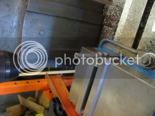
Step 1
Find the center of the ends of the casting. I prefer the milling machine for this operation but the choice is up to you. Once I machine the end I find center and drill it for a lathe center.
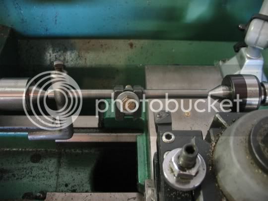
Step 2
Turn the ends of the crank between centers on the lathe. I put a piece of bartsock between the centers on the lathe and take a pass and measure the diameter at each end to make sure there is no taper. If there is taper the tailstock needs to be adjusted because it is not centered. It is very important that there is no taper (ie. the tailstock is centered). This photo is a mock up. You can see that the ends are already turned and the lathe dog is not set to drive anything. I use a bolt with washers in the cent to keep the crank from flexing. You can see that a dead center is used at the head end and a live center is used at the tailstock.
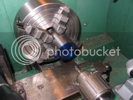
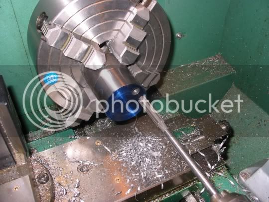
Step 3
To turn the throw a jig is needed. Use a round piece of 1018 steel and face one end. Use layout dye to mark the center and mark the offset throw center. Hold the piece of stock in a four jaw chuck and drill the offset hole the size of the crank end. Use the lathe for this unless you are absolutely sure your mill head is perfectly vertical. I prefere the lathe for this operation.
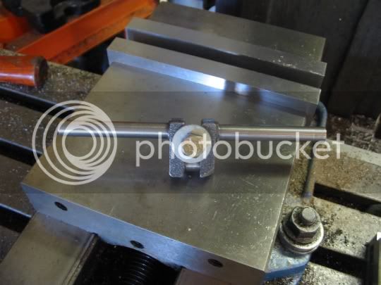
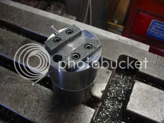
Step 4
Make blocks for either side of the crank to hold it. I put screws in the clamping holes to show more clearly where they are. Use grub screws (set screws) in place of the screws to hold the crank.
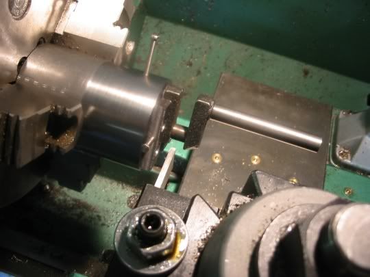
Step 5
Use a tool HSS tool or a heavy cutoff tool to turn the throw.
That is about all I have on this. Feel free to add additional suggestions or notes.
")
This is by no means an original approach. This was suggested on plans to an engine I built and worked very well. Feel free to add additional data as you see fit.
Note: Some of the pictures are for reference only. They are mock ups to show the approximate operation because as usual I didn't take enough pictures during the actual process.
Step 1
Find the center of the ends of the casting. I prefer the milling machine for this operation but the choice is up to you. Once I machine the end I find center and drill it for a lathe center.
Step 2
Turn the ends of the crank between centers on the lathe. I put a piece of bartsock between the centers on the lathe and take a pass and measure the diameter at each end to make sure there is no taper. If there is taper the tailstock needs to be adjusted because it is not centered. It is very important that there is no taper (ie. the tailstock is centered). This photo is a mock up. You can see that the ends are already turned and the lathe dog is not set to drive anything. I use a bolt with washers in the cent to keep the crank from flexing. You can see that a dead center is used at the head end and a live center is used at the tailstock.
Step 3
To turn the throw a jig is needed. Use a round piece of 1018 steel and face one end. Use layout dye to mark the center and mark the offset throw center. Hold the piece of stock in a four jaw chuck and drill the offset hole the size of the crank end. Use the lathe for this unless you are absolutely sure your mill head is perfectly vertical. I prefere the lathe for this operation.
Step 4
Make blocks for either side of the crank to hold it. I put screws in the clamping holes to show more clearly where they are. Use grub screws (set screws) in place of the screws to hold the crank.
Step 5
Use a tool HSS tool or a heavy cutoff tool to turn the throw.
That is about all I have on this. Feel free to add additional suggestions or notes.