- Joined
- Aug 25, 2007
- Messages
- 3,890
- Reaction score
- 715
I did my very first real CNC work today on my newly converted Enco Mill/Drill. Took me over 8 hours of redrawing, reprocessing with CAM and cutting test pieces using MDF until I finally got it right. What a learning curve!
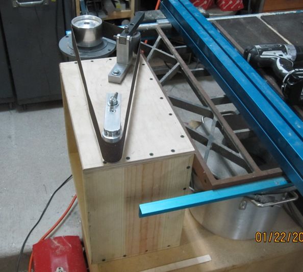
So, on to the real subject at hand. Ever since I first saw one of these, I've wanted one.

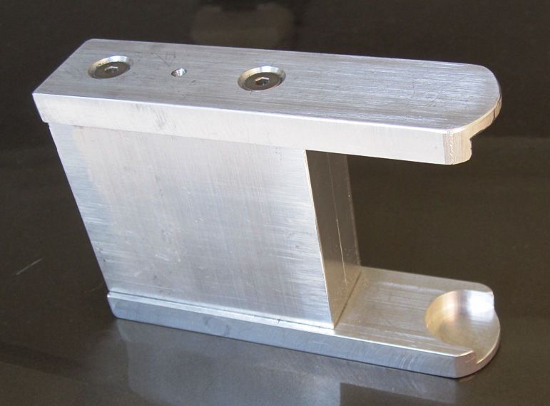
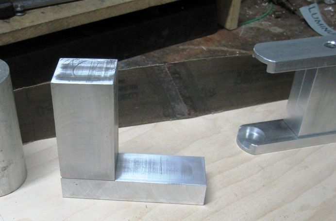
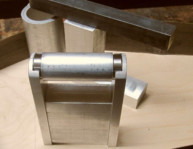
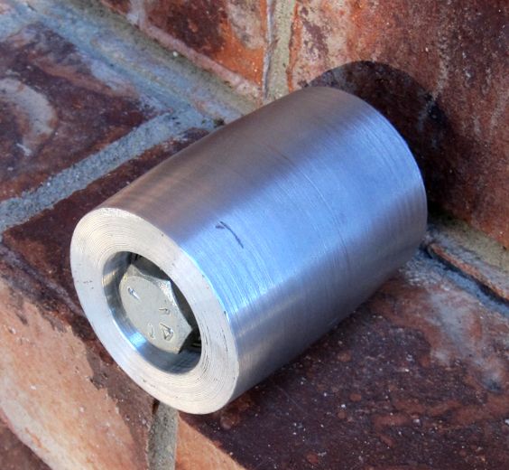
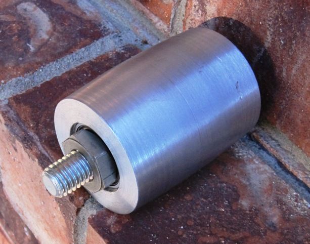
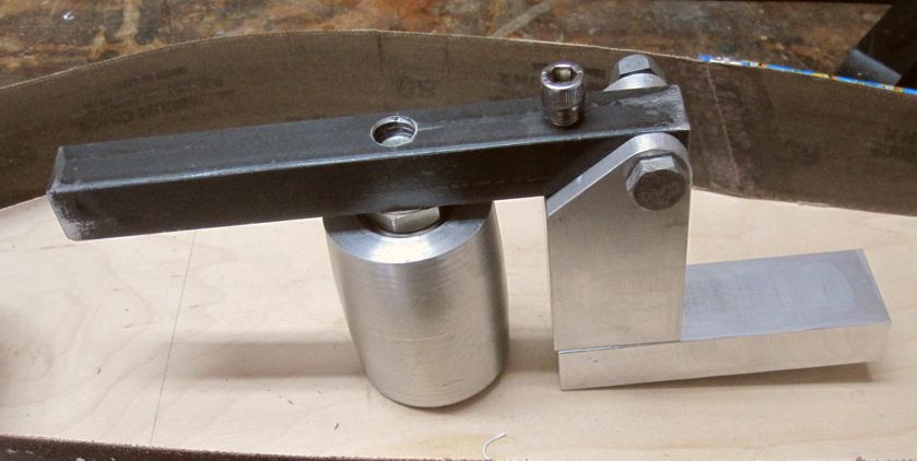
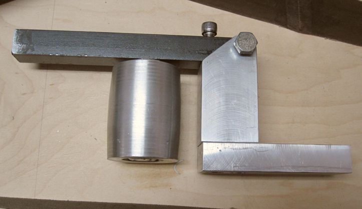
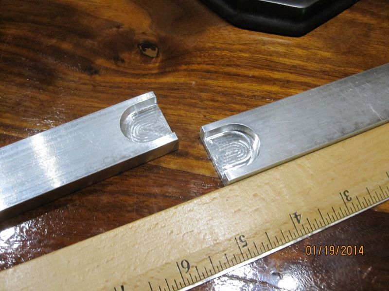
So, I've decided to add one to my small, already crowded shop. The two pieces I started with, above, will hold the small drum on the outboard end of the grinder and be used for grinding very small, inside radius's. The slotted ends will accept interchangeable drum sizes fitted with 7/8" OD x 3/8" ID ball bearings on each end. The overall design is really pretty simple. Here are drawings done in Visio...
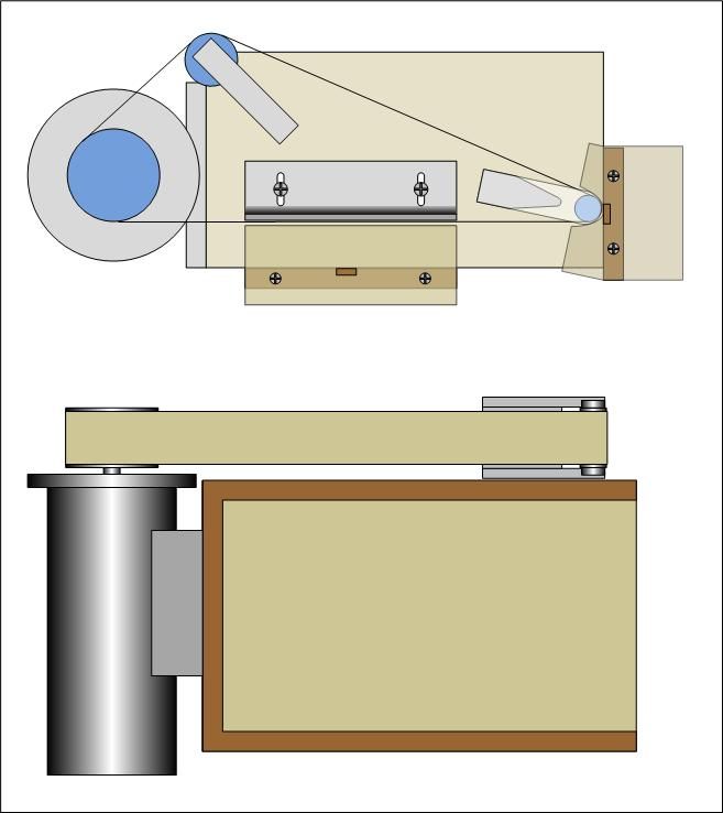
Mine will use a 2" x 48" belt.
Chuck
So, on to the real subject at hand. Ever since I first saw one of these, I've wanted one.
So, I've decided to add one to my small, already crowded shop. The two pieces I started with, above, will hold the small drum on the outboard end of the grinder and be used for grinding very small, inside radius's. The slotted ends will accept interchangeable drum sizes fitted with 7/8" OD x 3/8" ID ball bearings on each end. The overall design is really pretty simple. Here are drawings done in Visio...
Mine will use a 2" x 48" belt.
Chuck
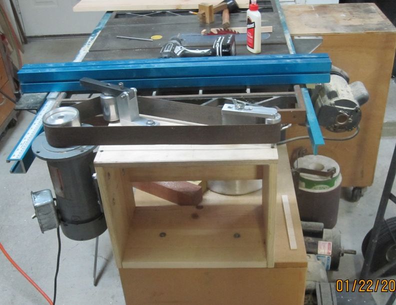
") I'd like to make it convertible from horizontal to vertical so I could replace my vertical 2" x 48" belt grinder, but so far I haven't figured out an easy way to do it.
I'd like to make it convertible from horizontal to vertical so I could replace my vertical 2" x 48" belt grinder, but so far I haven't figured out an easy way to do it.