Hi folks,
It's been a while since I've posted to the forum. I am still saving for the purchase of a mill and a lathe so in the meantime I am trying to keep byself busy with Solidworks. I hope somebody can help with the following...
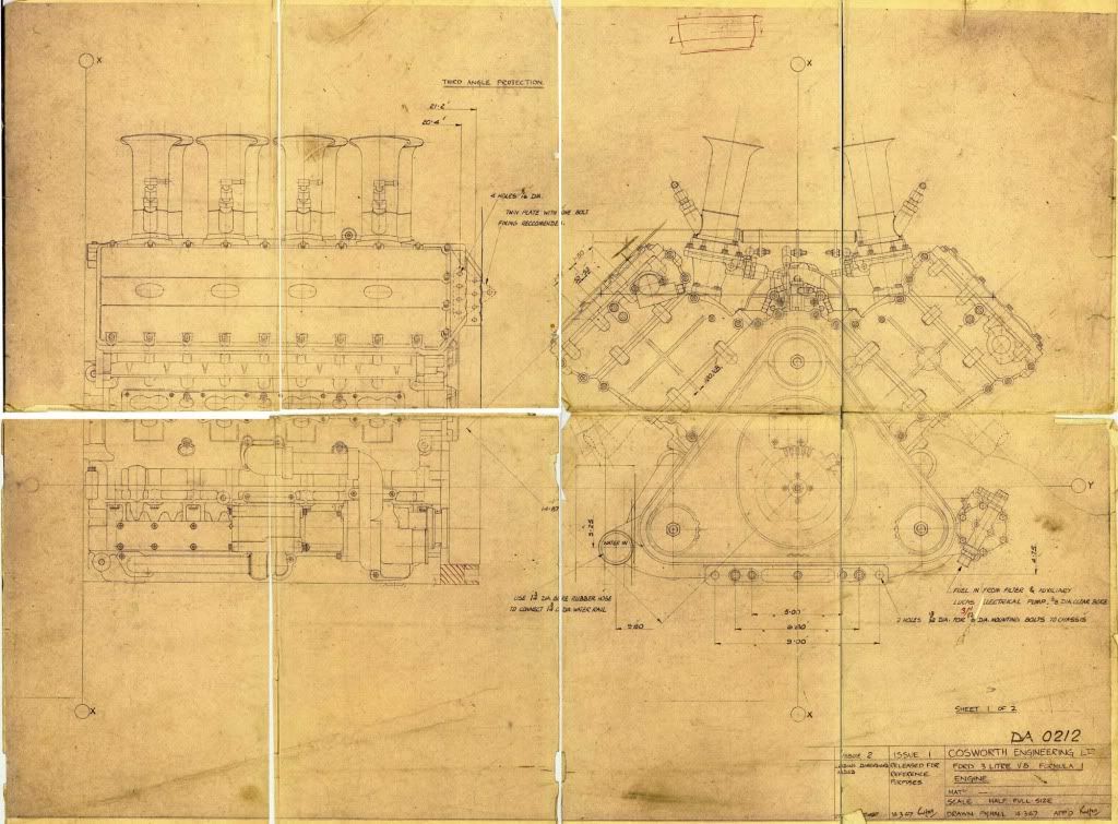
I've got the following information on the Cosworth DFV engine from historicengines.com :
[size=10pt]Crankcase:
Description: 90° V8 crankcase and cylinders cast together in aluminum. Wet cast iron cylinder liners sealed with O-rings. Steel,
coated iron, and nikasil alloy liners were also tried. Nikasil alloy liners saved 8 lb in overall engine weight, and were standard by
1983.
Weight (with clutch): 370 lb / 168 kg
Overall width: 27.0" (686 mm)
Overall length: 21.5" (545 mm)
Bore: 3.373" / 85.674 mm
Stroke: 2.555" / 64.8 mm
Bore spacing: 4.100" / 104.1 mm
Deck height: 6.505" / 165.2 mm (crankshaft centerline to deck surface)
Crankshaft height: 5.23" / 132.8 mm (crankshaft centerline to external sump bottom)
Cylinder stagger: 0.375" / 9.5 mm (left ahead of right)
Materials: Cast aluminum block and head, forged steel crank and rods (earliest DFV cranks were billet), forged aluminum pistons,
cast magnesium covers.
Firing order: 1-8-3-6-4-5-2-7
Compression ratio: 11.0:1 (approx.)
Fuel: 101 octane (M.M. - motor method) minimum
Rotation: clockwise when viewing front of engine
Crankshaft:
Description: single plane ("flat") common throw (2 rods per crank pin, no offset), forged nitrided steel (earliest cranks were billet
steel), 5 main bearing crankshaft, hollow crank pins, weight 32 lbs / 14.5 kg, thrust taken on #3 main bearing, 8 bolts on flywheel
flange.
Main journal diameter: 2.3755" to 2.3750" / 60.3 mm
Rod bearing diameter: 1.9370 to 1.9375" / 49.2 mm (same as Cosworth FVA: Bearing is Cosworth part number FA0067)
Connecting rod journal diameter: 1.9375" / 1.9370"
Crankshaft: End float: 0.004" / 0.009"
Connecting rod side clearance (big end): 0.006" / 0.012"
Piston :
Description: forged aluminum, 4 valve notches. Full floating wrist pin.
Piston compression height: 1.469 / 37.3 mm
Weight: ~328 grams (with rings, without pin)
Ring width:
top: 0.0315"/0.80 mm
middle: 0.0410"/1.04 mm
oil: 0.160"/4.06 mm
Piston ring gap (all rings): 0.017" to 0.022"
Connecting rod:
Description: forged steel, H-beam, fully machined connecting rods.
Bolts: 3/8" UNF
Connecting rod length: 5.23" (132.842 mm)
Wrist Pin length: 2.500" (63.5 mm)
Wrist pin diameter: 0.812" (20.638 mm)
Wrist pin end float: 0.000" ± 0.001" (retained by clips)
Rod/Stroke ratio: 2.05[/size]
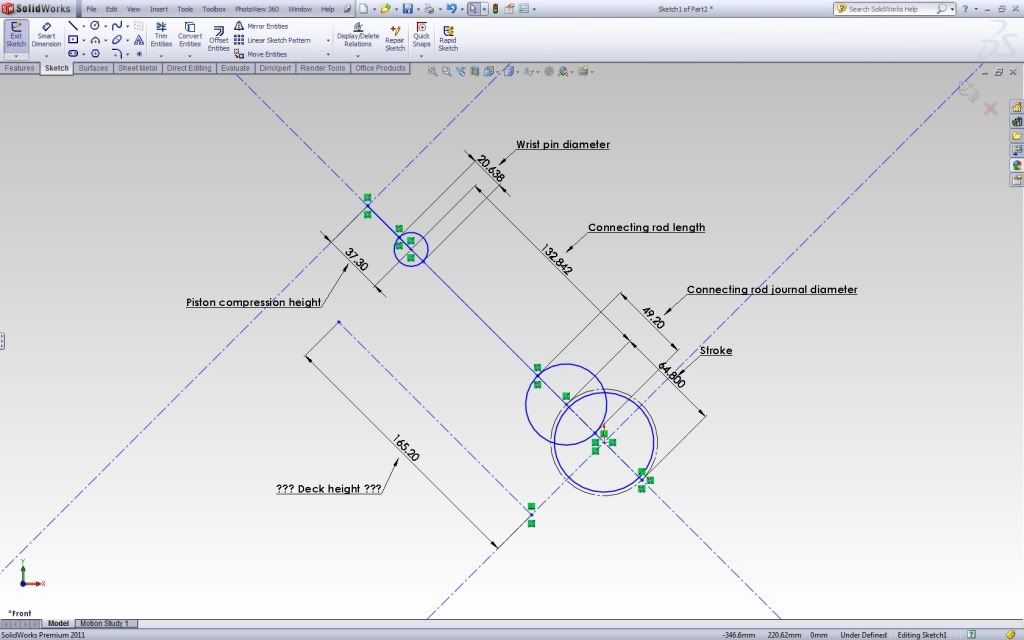
I am attempting to begin modelling in solidworks but I think I am probably going wrong somewhere. Please bear with me as I am still getting my head around a lot of engine terminology. In the following picture I think I have put in all the dimensions properly (I think) but if you look at the Deck Height it does not even clear the center of the wrist pin diameter:
I was not sure about what some terms such as deck height and compression height referred to so I have been using these diagrams that I found online:
The distance the deck height seems short by is curiously close to the dimension for the piston compression height. Anybody any pointers on where I could be going wrong? ???
It's been a while since I've posted to the forum. I am still saving for the purchase of a mill and a lathe so in the meantime I am trying to keep byself busy with Solidworks. I hope somebody can help with the following...
I've got the following information on the Cosworth DFV engine from historicengines.com :
[size=10pt]Crankcase:
Description: 90° V8 crankcase and cylinders cast together in aluminum. Wet cast iron cylinder liners sealed with O-rings. Steel,
coated iron, and nikasil alloy liners were also tried. Nikasil alloy liners saved 8 lb in overall engine weight, and were standard by
1983.
Weight (with clutch): 370 lb / 168 kg
Overall width: 27.0" (686 mm)
Overall length: 21.5" (545 mm)
Bore: 3.373" / 85.674 mm
Stroke: 2.555" / 64.8 mm
Bore spacing: 4.100" / 104.1 mm
Deck height: 6.505" / 165.2 mm (crankshaft centerline to deck surface)
Crankshaft height: 5.23" / 132.8 mm (crankshaft centerline to external sump bottom)
Cylinder stagger: 0.375" / 9.5 mm (left ahead of right)
Materials: Cast aluminum block and head, forged steel crank and rods (earliest DFV cranks were billet), forged aluminum pistons,
cast magnesium covers.
Firing order: 1-8-3-6-4-5-2-7
Compression ratio: 11.0:1 (approx.)
Fuel: 101 octane (M.M. - motor method) minimum
Rotation: clockwise when viewing front of engine
Crankshaft:
Description: single plane ("flat") common throw (2 rods per crank pin, no offset), forged nitrided steel (earliest cranks were billet
steel), 5 main bearing crankshaft, hollow crank pins, weight 32 lbs / 14.5 kg, thrust taken on #3 main bearing, 8 bolts on flywheel
flange.
Main journal diameter: 2.3755" to 2.3750" / 60.3 mm
Rod bearing diameter: 1.9370 to 1.9375" / 49.2 mm (same as Cosworth FVA: Bearing is Cosworth part number FA0067)
Connecting rod journal diameter: 1.9375" / 1.9370"
Crankshaft: End float: 0.004" / 0.009"
Connecting rod side clearance (big end): 0.006" / 0.012"
Piston :
Description: forged aluminum, 4 valve notches. Full floating wrist pin.
Piston compression height: 1.469 / 37.3 mm
Weight: ~328 grams (with rings, without pin)
Ring width:
top: 0.0315"/0.80 mm
middle: 0.0410"/1.04 mm
oil: 0.160"/4.06 mm
Piston ring gap (all rings): 0.017" to 0.022"
Connecting rod:
Description: forged steel, H-beam, fully machined connecting rods.
Bolts: 3/8" UNF
Connecting rod length: 5.23" (132.842 mm)
Wrist Pin length: 2.500" (63.5 mm)
Wrist pin diameter: 0.812" (20.638 mm)
Wrist pin end float: 0.000" ± 0.001" (retained by clips)
Rod/Stroke ratio: 2.05[/size]
I am attempting to begin modelling in solidworks but I think I am probably going wrong somewhere. Please bear with me as I am still getting my head around a lot of engine terminology. In the following picture I think I have put in all the dimensions properly (I think) but if you look at the Deck Height it does not even clear the center of the wrist pin diameter:
I was not sure about what some terms such as deck height and compression height referred to so I have been using these diagrams that I found online:
The distance the deck height seems short by is curiously close to the dimension for the piston compression height. Anybody any pointers on where I could be going wrong? ???