Owen_N
Well-Known Member
Continuation:
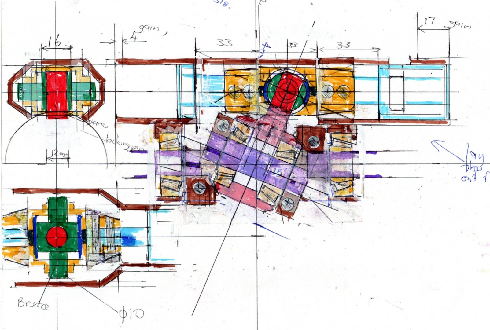
New idea!. allow side motion within the piston.
I will draw up outrigger pins to help stabilise this.
this should give enough freedom to take up cyclical misalignment.
About 2mm each way should be enough.
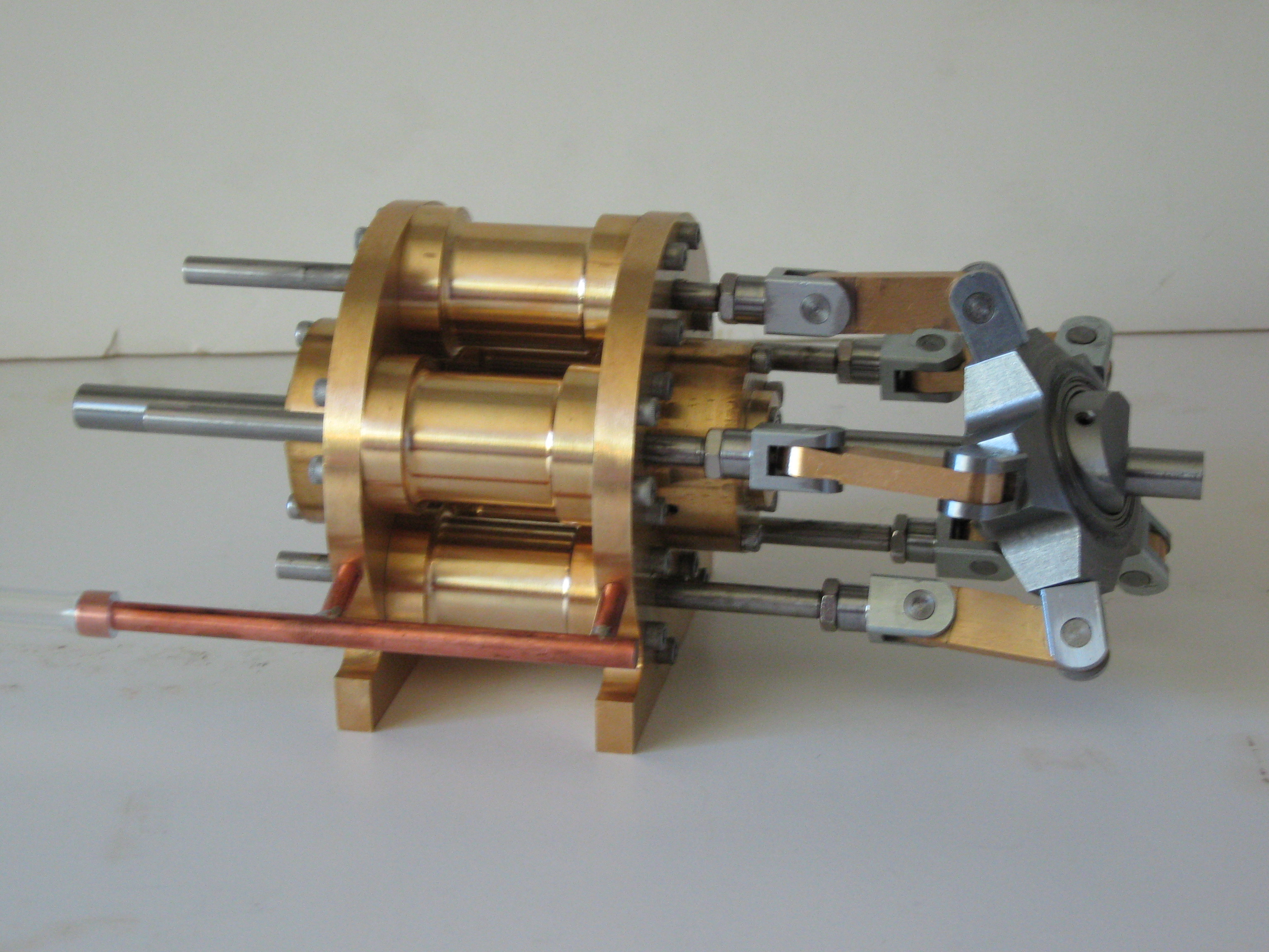
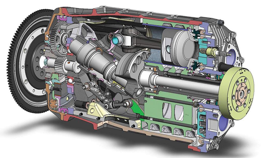
I will revert to the previous crank spacing, but with a hub unit more like an old-style car wheel and axle stub.
I can paste two drawings together as a start.
Drawing to follow.
<edit>
The steadying journals are bronze, high finish , running on aluminium.
They are not intended to take significant bearing loading, so the root plate of 2mm thickness should not be overstressed.
What are the possible loading modes and modes of failure that need more investigation?
1)- distribution of bending loads into the bearing ring? This is backed up by a substantial inner ring.
2)- distribution of load into taper bearings?
There is substantial leverage, but a lot of this will appear as radial loading.
There is no easy way of calculating whether the static axial loading could be locally exceeded.
This is a matter of testing in an actual design.
There is a roller retailing lip that could be overloaded, but determining that kind of loading is not straightforward.
3)-transition from rectangular to round on the piston bolting plates?
Possibly the side plates can be extended over the top of the piston extensions as a fillet, so that is not a major problem.
I can look into this detail.
4)- rocking motion in the 22mm bearing part transferring loading to the side bearings, and bending moment.
The maximum side displacement occurs at 60 degrees off top dead centre, but there is some side drag due to
friction and possible bearing tilt, and bending moment.
I can work out a potential side velocity profile, side force due to friction, and applied bending moment.
Actual rocking motion is very small.
Does the 22mm diameter need to be extended further out?
What is a good diameter to width ratio?
Side force can be about 0.2-0.3 x the applied force of 5kN from the combustion.
At what point is side velocity significant? It drops to around zero at 60 degrees, where the two pistons in line move in opposite directions.
I would presume that side velocity is maximum at around 30 degrees rotation
Pressure at this point is still higher than 50% of full pressure, so side F = 0.3 x 3kN and moment arm is
12mm, so M = 10.8 N-m
bearing center spacing is 30mm, so force at bearings is 10.8/30x 10^-3 = 360N
leverage at the overhung bearing base = 8mm approx , so M at the stub base is 360 x 8 x 10^-3 = 2.8 N-m
tearout stress at the base of the stub is tricky to work out, - possibly similar to a 2mm wall tube 10mm diameter.
I = pi/12( r1^4 - r2^4)
r1 = 5, r2 = 3
623-81,
142 x 10^-12
M = 2.8
smax = 2.8 x 5 x 10^ -3/142 x 10^-12
= 0.09859 x 10^9
= 98 Mpa, so this is not a problem.
Actual bearing pressure - area = 10 x 8 x 10^-6
F = 360
P = F/A = 360/80x 10^-6 = 4.5 MPa
This is OK.
5) effect of combined twisting, extending and "stroke" motion at:
- parasite friction.
- increasing stress in components.
The worst effect is during compression, but this is at a relatively low chamber pressure, so is not a limiting stress case.
Working out parasitic drag in relation to power output could be quite tricky, as power consumed depends on the integral of load and surface velocity. The piston rings produce a fair bit of parasitic drag- maximum drag force = area x pressure x 0.3
area = pi D x 1.5 x 10^-6 = 141 x10^-6 sq m
F drag, max = PA = 70 x 10^5 x 141 x 10^-6 x 0.3 = 290 N, compared with piston thrust, which is 5 kN
However, power consumed is a smaller proportion, as it depends on piston velocity and pressure integrated together,
over the P-displacement curve. Likely much less than 5.8%. (*correction)
I wouldn't bother working all the friction factors out, as they will likely be quite small, and have no effect on peak stresses.
**********************************************************************************************************************************
* Looking at a crank action, it seems odd that power is directly related to swept volume, given that power is also related
to torque and rpm.
A crank has odd torque multiplying properties. You would think that a "constant crank radius" system would transfer greater average torque over the power stroke, which corresponds to greater energy transfer for that stroke.
The swept volume is the same in both cases.
for instance, a rack running over a gear wheel.
It doesn't seem to work that way.
Rewinding the mechanism could be a bit tricky, such that no net energy is consumed.
You need to spin up a flywheel, and hit a gear reverse at the top and bottom of the stroke.
This also keeps system inertia in "the loop".
The "tooth and notch" split cycle engine would work this way, but that engine has some problem areas,
as discussed in its own thread.
A reciprocating engine works better with a sinusoidal or similar motion, and converting this to fairly constant rotation speed.
It could be constant acceleration, as in the cam profile.
I think "harmonic" and "sinusoidal" are similar.
If you superimpose this motion with a cam, then the cam slope works in a similar way to crank leverage.
****************************************************************************************************************************
Question:
Any opinions or actual experience of running a bronze shaft against an aluminium bearing?
The centre-piston components don't need to be made of eutectic Al-Si.
What would be a better alloy to use there?
Possibly thermal temper stability, and temper level, are considerations.
Would 6063 be any good?
Do I need the hardened steel slipper plates at all?
Is my bronze choice of tin-lead-phosphorous the best bet?
Should aluminium bronze be considered?
I think 2-stroke con-rods are normally made of aluminium-bronze, with steel needle roller liner inserts.
*****************************************************************************************************************************
New idea!. allow side motion within the piston.
I will draw up outrigger pins to help stabilise this.
this should give enough freedom to take up cyclical misalignment.
About 2mm each way should be enough.
I will revert to the previous crank spacing, but with a hub unit more like an old-style car wheel and axle stub.
I can paste two drawings together as a start.
Drawing to follow.
<edit>
The steadying journals are bronze, high finish , running on aluminium.
They are not intended to take significant bearing loading, so the root plate of 2mm thickness should not be overstressed.
What are the possible loading modes and modes of failure that need more investigation?
1)- distribution of bending loads into the bearing ring? This is backed up by a substantial inner ring.
2)- distribution of load into taper bearings?
There is substantial leverage, but a lot of this will appear as radial loading.
There is no easy way of calculating whether the static axial loading could be locally exceeded.
This is a matter of testing in an actual design.
There is a roller retailing lip that could be overloaded, but determining that kind of loading is not straightforward.
3)-transition from rectangular to round on the piston bolting plates?
Possibly the side plates can be extended over the top of the piston extensions as a fillet, so that is not a major problem.
I can look into this detail.
4)- rocking motion in the 22mm bearing part transferring loading to the side bearings, and bending moment.
The maximum side displacement occurs at 60 degrees off top dead centre, but there is some side drag due to
friction and possible bearing tilt, and bending moment.
I can work out a potential side velocity profile, side force due to friction, and applied bending moment.
Actual rocking motion is very small.
Does the 22mm diameter need to be extended further out?
What is a good diameter to width ratio?
Side force can be about 0.2-0.3 x the applied force of 5kN from the combustion.
At what point is side velocity significant? It drops to around zero at 60 degrees, where the two pistons in line move in opposite directions.
I would presume that side velocity is maximum at around 30 degrees rotation
Pressure at this point is still higher than 50% of full pressure, so side F = 0.3 x 3kN and moment arm is
12mm, so M = 10.8 N-m
bearing center spacing is 30mm, so force at bearings is 10.8/30x 10^-3 = 360N
leverage at the overhung bearing base = 8mm approx , so M at the stub base is 360 x 8 x 10^-3 = 2.8 N-m
tearout stress at the base of the stub is tricky to work out, - possibly similar to a 2mm wall tube 10mm diameter.
I = pi/12( r1^4 - r2^4)
r1 = 5, r2 = 3
623-81,
142 x 10^-12
M = 2.8
smax = 2.8 x 5 x 10^ -3/142 x 10^-12
= 0.09859 x 10^9
= 98 Mpa, so this is not a problem.
Actual bearing pressure - area = 10 x 8 x 10^-6
F = 360
P = F/A = 360/80x 10^-6 = 4.5 MPa
This is OK.
5) effect of combined twisting, extending and "stroke" motion at:
- parasite friction.
- increasing stress in components.
The worst effect is during compression, but this is at a relatively low chamber pressure, so is not a limiting stress case.
Working out parasitic drag in relation to power output could be quite tricky, as power consumed depends on the integral of load and surface velocity. The piston rings produce a fair bit of parasitic drag- maximum drag force = area x pressure x 0.3
area = pi D x 1.5 x 10^-6 = 141 x10^-6 sq m
F drag, max = PA = 70 x 10^5 x 141 x 10^-6 x 0.3 = 290 N, compared with piston thrust, which is 5 kN
However, power consumed is a smaller proportion, as it depends on piston velocity and pressure integrated together,
over the P-displacement curve. Likely much less than 5.8%. (*correction)
I wouldn't bother working all the friction factors out, as they will likely be quite small, and have no effect on peak stresses.
**********************************************************************************************************************************
* Looking at a crank action, it seems odd that power is directly related to swept volume, given that power is also related
to torque and rpm.
A crank has odd torque multiplying properties. You would think that a "constant crank radius" system would transfer greater average torque over the power stroke, which corresponds to greater energy transfer for that stroke.
The swept volume is the same in both cases.
for instance, a rack running over a gear wheel.
It doesn't seem to work that way.
Rewinding the mechanism could be a bit tricky, such that no net energy is consumed.
You need to spin up a flywheel, and hit a gear reverse at the top and bottom of the stroke.
This also keeps system inertia in "the loop".
The "tooth and notch" split cycle engine would work this way, but that engine has some problem areas,
as discussed in its own thread.
A reciprocating engine works better with a sinusoidal or similar motion, and converting this to fairly constant rotation speed.
It could be constant acceleration, as in the cam profile.
I think "harmonic" and "sinusoidal" are similar.
If you superimpose this motion with a cam, then the cam slope works in a similar way to crank leverage.
****************************************************************************************************************************
Question:
Any opinions or actual experience of running a bronze shaft against an aluminium bearing?
The centre-piston components don't need to be made of eutectic Al-Si.
What would be a better alloy to use there?
Possibly thermal temper stability, and temper level, are considerations.
Would 6063 be any good?
Do I need the hardened steel slipper plates at all?
Is my bronze choice of tin-lead-phosphorous the best bet?
Should aluminium bronze be considered?
I think 2-stroke con-rods are normally made of aluminium-bronze, with steel needle roller liner inserts.
*****************************************************************************************************************************
Attachments
Last edited: