Help me upgrade my ignition!

Home Model Engine Machinist Forum

Help Support Home Model Engine Machinist Forum:

This site may earn a commission from merchant affiliate links, including eBay, Amazon, and others.

Swede

Well-Known Member
Joined
Apr 7, 2011
Messages
460
Reaction score
10
Ignition tends to be a real difficulty with an IC model, especially when dealing with multiple cylinders. As the RPM goes up, and the number of cylinders goes up, the dwell time, the time the coil is being "charged", becomes smaller. Of course, the spark is fired when the points (mechanical or electronic) open.

I ran my engine yesterday for the first time in quite a while, and it ran well, except a couple of the cylinders were not firing; they were along for the ride. Oddly enough, they were at the top. Usually it is bottom cylinders that don't fire, being oil soaked and such.

This engine started life with a hall chip, but I could not keep the hall device alive, and in the end, went with a mechanical system, and a 12V car coil.

I decided to take the #1 cylinder down to check the valves, piston, rod, & plug, and to also check the distributor.

nr05.jpg


Everything looked good, mechanically. I was pleased at how little physical wear there was. This engine has been run hard. I pulled off the piston and checked the compression in the cylinder. It was satisfyingly "springy." Very little leakage. The rings looked good. The piston pin, rod, bushings, etc, all looked fine.

There was some carbon built up around the exhaust valve. This engine runs too cool... I wish there was some way to get it a bit hotter-running, but leaning it out results in too much unreliability.

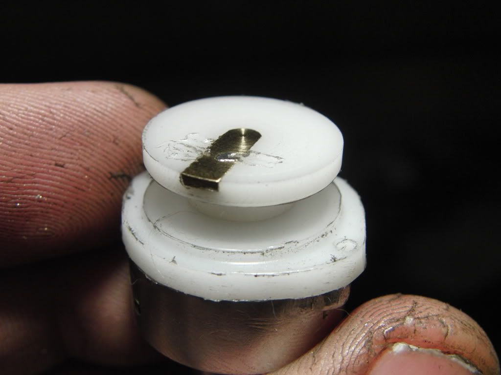
On to the ignition. The rotor is a delrin turning with an adjustable contact made from a PC board. The set screws let me rotate the angle. Deeper in the base is a rotating disk that mounts the point set and lets me adjust spark timing during the run. The blue wire is there to allow this movement. Point contacts are mounted in another piece of delrin, to the right.

nr07.jpg


This pops free, and the mechanism of the distributor can be seen:

nr08.jpg


Hard to see, but there is a 9-lobed cam from hardened tool steel that actuates the point, a lever of brass with a steel cam insert. The gap is about 1mm. This drives a transistorized ignition.

I've always been suspicious that my ignition is weak, and I'd like to improve it, preferably outside the distributor. Here is the circuit I am using. I am not really smart on ignitions, and it is an area that I really need to brush up on.

tim7.jpg


The other problem with this setup is that the engine, stand, and circuit are positive ground, necessitated because of the NPN darlington. I will say this, it is robust in the sense that it has never failed. I simply feel that it is weak.

Would an increase in voltage give me a bit more "oomph?" Any suggestions are appreciated. I'd really like to get this thing where every cylinder fires every time, and evenly. Thanks!


Hi Swede,
You're correct in saying that the greater the number of cylinders the less time there is for dwell. When I first built my 302 engine I had points in the distributor. At that time, mid 70's, there were not electronic ignitions for model engines. Wanting to keep the distributor somewhat to scale with the engine it had an outside diameter of 1.062. The engine never ran well because I couldn't get enough cam action to open the points far enough. I think they would open about .012. I got discouraged trying to get it to run and eventually redesigned the distributor, still using points, but took a completely different approach. It ran better but still no cigar. A couple of years ago I went electronic. I have 2 versions of electronic ignitions, one by Jerry Howell and one by S&S. They both seem to work well except the S&S runs out of spark at higher rpms. (6,800-7,500). With your radial I doubt that you would see rpms in that range.
To trigger the ignition I use a Hall sensor with one magnet inside the distributor. There is an interrupter disc with windows cut into it. It has to be made from steel. I increased the distributor diameter to use an 8 cylinder cap that Bruce Satra used to sell. S&S now sells them. I have had no troubles with the Hall sensor burning out, at least not on this engine. It's imperative that there is a good ground.
In your case I would maybe start to look for something else as the culprit. The reason for me saying this is because if only the 2 top cylinders aren't firing but all the other adjacent cylinders are then it would seem like the dwell is sufficient for proper operation.
As far as the positive ground ignition that shouldn't hurt anything. The engine doesn't know any better.
There has been quite a bit of discussion on running engines will Halls sensors. The best I can say is nobody has a definitive answer as to why the blow. Some say that the return path for the spark is leaking to the ground on the sensor and that it should be meticulously insulated. Others say that the spark return is jumping from the magnet to the sensor and to glue a small piece of plastic to the face of the magnet to insulate it. I certainly don't have an answer but other than blowing some Hall sensors when I first go started I can say I've had good luck with them since then.
gbritnell
 
Thank you for the detailed reply. I went through a phase where I tried several hall sensors using these windowed steel cams...

nr10.jpg


The hall chip went into a carrier in the base of the distributor. I even went so far as to drill and tap a strip of aluminum 1/4-32 for 9 spark plugs, and had the thing totally wired on the bench. With the distributor shaft chucked in a drill to spin it, I had a perfect orderly firing of the plugs. There was nothing I could do on the bench to make it NOT work. Everything looked good.

But in the engine, I blew up chip after chip. It was really tedious to have to install a new chip, because the entire distributor had to come apart. I worked for days, pretty much went crazy, and I could never make it go. All I can conclude is that the location of my chip was perhaps too close to the distributor posts or something. Or there was arcing going on. I do remember that when it ran, I was getting higher RPM's than with the mechanical system.

I've often thought these vanes could also be used for a photoelectric setup, but the same issues might crop up.

I need to revisit hall if all else fails. My goal is more reliability than performance. It's certainly not a race engine and is very heavy, so it's just for bench running.

Do you think reshaping the distributor cam to a profile that would create more dwell might help? Since the points are switching a transistor, they do not spark or carry much more than a couple hundred mA current. Basically, it's just a switch.

Would capacitance anywhere in the circuit help?

Thanks again, I'd really like to improve on this. :D
 
> Would capacitance anywhere in the circuit help?

I suspect it might. The transistor goes 'off' to trigger the spark, with the inductance in the primary and secondary serving as an energy storage element. The sudden *change* in the primary current causes the spark, and without the capacitor, the ignition coil also tries to burn up the transistor as well as step up the primary voltage.

Try something like, uh, .05 uF @ 600 volts, with a film dialectric. (looks at an old one from somewhere laying out on his desk as he pauses while typing.) It will need a certain amount of experimentation.

As for the hall effect chips 'frying' while installed in the distributor, I've heard of that being a serious problem. Solution is to remove them from the distributor, either by adding a well-shielded compartment *below* where all those sparks are jumping around as that rotor comes close (or touches) the buttons, or do as you did with conventional points.

dy
 
I had the same issues in a v8. Distributor is 1 inch dia. The hall effect sensor is in the distributor. I added zener diodes to the hall effect sensor right in the distributor to ground the spikes. I also added a 20k ohm resistor in the coil lead to reduce spike generating. Its been working for a year now. I don't think the spark is as hot as a Kettering system but it's good enough. I'm pretty careful to route the low voltage wires away from the high tension ones too. Another issue that took me a while to discover is that hall sensors are very temperature intolerant and will die if they get too hot. What I found was the ignition would get working crappy and in not too much time wouldn't work at all. I'd change the sensor and it'd be working again until I allowed the motor to run up to a high temperature. I changed to a sensor rated a 150 degrees C and I've been fine ever since. I use a shutter for rotating the spark.
 
Swede said:
nr10.jpg


The hall chip went into a carrier in the base of the distributor. I even went so far as to drill and tap a strip of aluminum 1/4-32 for 9 spark plugs, and had the thing totally wired on the bench. With the distributor shaft chucked in a drill to spin it, I had a perfect orderly firing of the plugs. There was nothing I could do on the bench to make it NOT work. Everything looked good.

But in the engine, I blew up chip after chip.

That looks like its part of your answer, the distributor was isolated electrically, so the spark went to the plugs. High voltage will always take the easiest path to ground, and once current is flowing, two paths or more may alternate as the easiest.

With your current setup, eliminate the screws holding the rotor contact, they will allow spark to jump below the rotor to the shaft. Ask any GM owner about rotor failures, their old HEI system would eventually burn through any rotor, no brand ones much quicker then factory ones.

Its good design practice to use zener diodes to dump dangerous voltages from various induction sources. The coil primary can hit 400 volts itself. There is not much protection available for secondary voltage, so it needs to be protected physically by proper location. One of the most elegant solutions I have ever seen was the Mitsubishi 3.0L distributor in Dodge minivans. It used a steel cover over all the electronics, with barely .001" clearance between it's only hole and the rotor shaft. Inside the distributor it used an optical pickup, but there is no reason a Hall effect unit would not work in its place.

In my opinion, the best way to use a hall sensor is with a bottle cap style window. The sensor and magnet are stationary, or on a moveable plate, with windows cut into the side of the metal cap. This leaves the cap to partially protect the hall sensor element in a similar manner to the Mitsubishi distributor.
 
Just want to add that the typical way of protecting electronics like this, is "snubber" diode, or flyback diode which is the more correct term. For a circuit like this, two diodes may be added, one parallel with the coil, and one with the transistor. Also as mentioned, a zener diode could be used to protect the hall sensor, but a zener is typically quite slow, so it may or may not react quick enough on these spikes.

It is also a good idea to place these protecting diodes as close to the part to be protected as possible.
 
Hi again Swede,
Here's the drawing for the distributor in my OHV 4 cylinder engine. It is basically the same as the 302 distributor. I have what jpeter calls a bottle cap interrupter. The magnet is mounted on a right angle post screwed to the floor of the distributor. The Hall chip is glued into an aluminum bracket that mounts to the side of the distributor with 2, 0-80 screws. The bracket allows the Hall sensor to go through the side of the distributor body and just clear the interrupter disc by about .007. My rotor is just a little smaller than the inside of my cap and the strap is super glued in place, no screws. The distance from my spark (rotor to terminals) to the Hall is substantial plus the rotor kind of shields it also. My rotor is made from some type of old terminal board material. I'm also attaching a photo of the distributor. I'm not saying that the ground for the spark couldn't migrate to my Hall sensor buy up till now I haven't had a problem.
gbritnell

View attachment 4 CYL OHV HALL DISTRIBUTOR.pdf

DISTRIB 3.jpg
 
Hello Swede, I made a distributor to the same design as George, just a bit smaller, about .8" OD, the ID is about .7". I was experiencing some trouble with the hall sensor burning out. The cramped spaces inside the distributer allowed the spark to go wherever. I had a screw in the rotor contact which was arcing out to the trigger wheel and hitting the sensor. Also I seen sparks going from the rotor to the to the top of the distributor base.

What I decided to do is isolate the rotor from the trigger wheel, hall sensor and distribotor body.


Here is a pic of my new design. You can see the rotor is completely isolated, the shaft that connects the rotor to the trigger wheel is made of acetal, and the contact is a tight fit to the slot it goes in. Also, I used a soldering iron to massage some material over the contact to help keep it in place.

CIMG2172.jpg


Kel


Its difficult, if not impossible to know the exact cause of sensor failure . High voltage coming from the ignition system, and going through the sensor seems to be the primary cause of failure, although its not the only possible cause. Its difficult to understand this until you see a high voltage spark jump to the sensor. If you feel it is, than the solution is to properly and completely insulate the entire sensor face and its leads. Some engines do not have fully insulated sensors and will not experience this problem, since every engine is unique in construction.

Another possibility that hasn't been brought up the use of a damaged sensor. This is caused by improper handling, soldering, or installation. The damaged caused failure may not become apparent until after several minutes or hours of use, and may also show up as an intermittent failure.

Any one experiencing sensor failures might want to read the information provided in the link below.

http://www.allegromicro.com/en/Products/Design/hall-subassemblies/

-MB


Hi Swede, I also have built a 9 cyl radial of the same design as yours. Mine is an older version that doesn't have a blower for proper fuel mixing. When mine runs, if I richen the fuel mixture the top cylinders will run fire properly but the lower cylinders will miss fire from being to rich, if I lean the mixture the bottom cylinders will run fine but the top cylinders will quit firing from being too lean. I figure the fuel is falling due to gravity in the intake plenum. I haven't tried to correct the problem yet, the engine runs fairly well and I really don't want to redesign the intake to incorporate a blower at this time. My engine also runs too cold, cylinder head temps are 125-130 degrees F. I am still using the original point arm and my rpms are limited to 3000.
With a carbon fiber prop it will idle at 1000 rpms. It does start easily but could use better fuel distribution. Dave
 
Shouldn't there be a condensor between your emmiter & collector to accellerate the collapsing field of the coil - as per the condensor across the points (without the transistor).

Without it your field collapse is only going to generate a fraction of the"OOMPH".

Ken
 
Ken I said:
Shouldn't there be a condensor between your emmiter & collector to accellerate the collapsing field of the coil - as per the condensor across the points (without the transistor).

Without it your field collapse is only going to generate a fraction of the"OOMPH".

Ken
In the Kettering ignition system, that condenser mainly functions to protect the points. It is a critical component in capacitive discharge ignitions, however.
 
While the condensor across the points does serve to protect them - that role is secondary to its role in collapsing the field.

When the circuit is opened the field collapses generating a reverse or back emf - in both primary and secondary windings of the coil.

The condensor effectively forms part of an LC circuit (although we are not really interested in that) the condensor conducts the rising voltage causing the field to collapse quicker, which causes the field to collapse even quicker - TaaDaa - avalanche - the field slams down - this brings about far larger voltages in the secondary than the simple winding ratio would suggest.

Disconnect the condensor from a points ignition system and you will get a bigger spark on the points - sure - what you won't get is spark at the plugs (or I should say a vastly diminished spark).

I'm not sure if the transistor doubles in this role of grounding the back emf - I doubt it.

http://www.homemodelenginemachinist.com/index.php?topic=12476.msg135213#msg135213

We've covered this ground before.

Ken
 
There's some great expertise here, no doubt. I'm going to approach this methodically. My first attempts will consist of a condenser to see if ignition characteristics are improved. After that, it might be time to attack the distributor itself a bit. If I can make the mechanical system (points) work well, I'd rather hang onto that. I literally tried (and burned) dozens of hall devices. If I had known, or thought about it a bit more, I would have run the distributor shaft down and through the rear crankcase, and created the hall setup at the bottom of the engine, rather than in the distributor base.

Mine is an older version that doesn't have a blower for proper fuel mixing.

Hi Dave - my blower really doesn't blow much, but it does seem to work to mix the fuel/air up a bit. If you wanted to, you could add an impeller without too much trouble, by pinning it to the oil pump gear, making it a sort of monolithic unit, and using a longer screw. There's plenty of room back there.

Mixture and the carb in general were tricky. Carbs made for viscous glow fuel, loaded with oil, simply don't work properly with gasoline. I found that just two or three clicks of the needle off of the proper location would dramatically alter how the engine runs. Once I found the sweet spot, I set it there. And I rarely touch it.

And that brings up an obvious "duh" moment, I need to verify that the mixture is where it needs to be. Varnish and gumming during storage can change things.

TY all for the help and comments. I hate being dumb about stuff like ignition systems. Time for some research. ;D


Now I'm not claiming to be an EE but do I know just enough about transistors to be dangerous. So here goes. For an NPN transistor to have collector-emitter current you need some base-emitter current. For that to happen you need a source of voltage to make the base somewhat more positive than the emitter, not too much more positive. If both the base and emitter are equal voltage, grounded in your case, there will be no collector current.

So I'd say, assuming the points ground the base, you need a pull-up resistor to get some base current going while the points are open. To do that you could place an appropriate sized resistor from 12v+ to the base to create a voltage divider circuit to place a couple of volts on the base when the points are open.

That brings up another point, you want to pull up the base, so collector current flows, when the points are closed, right? To do that most use a small PNP transistor circuit in the base to reverse the phase, in other words get the main transistor base voltage up when the points are closed, just the reverse of what you have. In your case though with so many cylinders to fire it might not matter cuz the dwell is about equal to the open time.

You electrical guys feel free to set me straight.
 
@jpeter I think he has 12v across the 40 ohm resister - but I may be wrong.

So here's my take on it. The lack of capacitor tuning the ignition coil will only result in very short duration low energy sparks. Also your circuit shows the device turning on with the points but with no turn off mechanism.

@ KEN I
The capacitor is not there to protect the points, if anything it causes greater wear. Its there to form a series resonant circuit with the coil primary resulting in a 400v primary voltage of a duration long enough to ignite the mixture. Without it the voltage is higher but of very short duration.

So in the basic kettering ignition the coil primary is connected to the capacitor across which the points (normally closed) are placed. The other side of the coil primary goes to the supply. Large currents flow through the coil primary and contacts to ground. When not running these currents are limited by the resistance of the coil primary. The current causes a magnetic field to build up in the ignition coil. When the points open the magnetic field collapses. The change of magnetic field induces a voltage in the secondary winding of the ignition coil leading to the spark.

There are several problems with this system. It uses a large current when the engine is running slowly or not at all. The current decreases with speed due to the time taken to recharge the magnetic field by virtue of the primary inductance. This results in weaker sparks at higher speeds. The wear on the points due to arcing results in maintenance issues and variations of timing as the points/cam wear.

The version which you are trying to emulate is the a transistor assisted ignition, in which the high current flow in the points is reduced by the use of a transistor. The collector on your device is the case which must be insulated from the motor. As long as you heatsink the transistor properly (either use an insulating kit or mount it on apiece of aluminium isolated with nylon screws) it should work fine (40 ohm resister will get hot too). Just rewire it to the circuit below, and ensure that the point open at the correct timing for ignition. The pulldown 100ohm resister is to speed up the turnoff of the device.

Hope this helps

picclock

Edit - It occurred to me that you also wanted the battery -ve to be ground, which can be achieved by placing the points across the 100 ohm resister and connecting the 40 ohm resister to +12V. However that would mean the ignition will fire when the points close.


TA IGN.jpg
 
jpeter and Picclock - excellent information. I am going to go out in my shop and verify (and properly draw) the schematic. That will be better than what I posted earlier. I think we're onto something here to improve the system.

I'll get it up ASAP.
 
Picclock - agree with your circuit diagram - with a capacitor exactly where I said it should be.

I never said it was there to protect the points (in a conventional system) Lakc did - I said that was merely incidental - and yes for part of the process it does make things worse - but overall its effect is beneficial - but my point all along is it is there as an LC agent to assist in collapsing the coil field, it is not simply there to suppress arcing at the points.

The original circuit posted by Swede does not have this capacitor - this is what I suggested to Swede is missing (not to mention the resistors in your diagram)

Fine post I'm not arguing with you.

Ken
 
@ KenI

>>Fine post I'm not arguing with you.

If anything I said caused offence please ignore it. It was never my intention to ruffle feathers, merely to help swede sort out his ignition issues - and hopefully douse a few misconceptions.

In the early days of electronic ignition systems a colleague and I had a small cottage industry going manufacturing electronic ignition units. Having made some for ourselves we found that we ended up making them for many people in the company where we worked. These were a more complex and efficient design than that used by swede. They had an inverter which charged a capacitor to 400v, and when the points opened the capacitor discharged into the coil primary causing the spark. This is a much superior system using almost zero current when not running, much lower current during operation, and consistent spark energy regardless of motor speed (up to the design limit of the circuit). The only problem we encountered was that normal ignition points are not happy with very low currents and we had to increase the point current to 50mA (0.05A) to maintain good operation. Also the circuit would maintain output down to an input voltage of 6V, well below that needed to crank the stater motor.

Ahh ! those were the days - Men were Men, Women were Women, and feeble over educated nerds were still outcasts .. . ;D

picclock


Latest posts

Back
Top