Heavier flywheels for the Kerzel hit and miss engine

Home Model Engine Machinist Forum

Help Support Home Model Engine Machinist Forum:

This site may earn a commission from merchant affiliate links, including eBay, Amazon, and others.
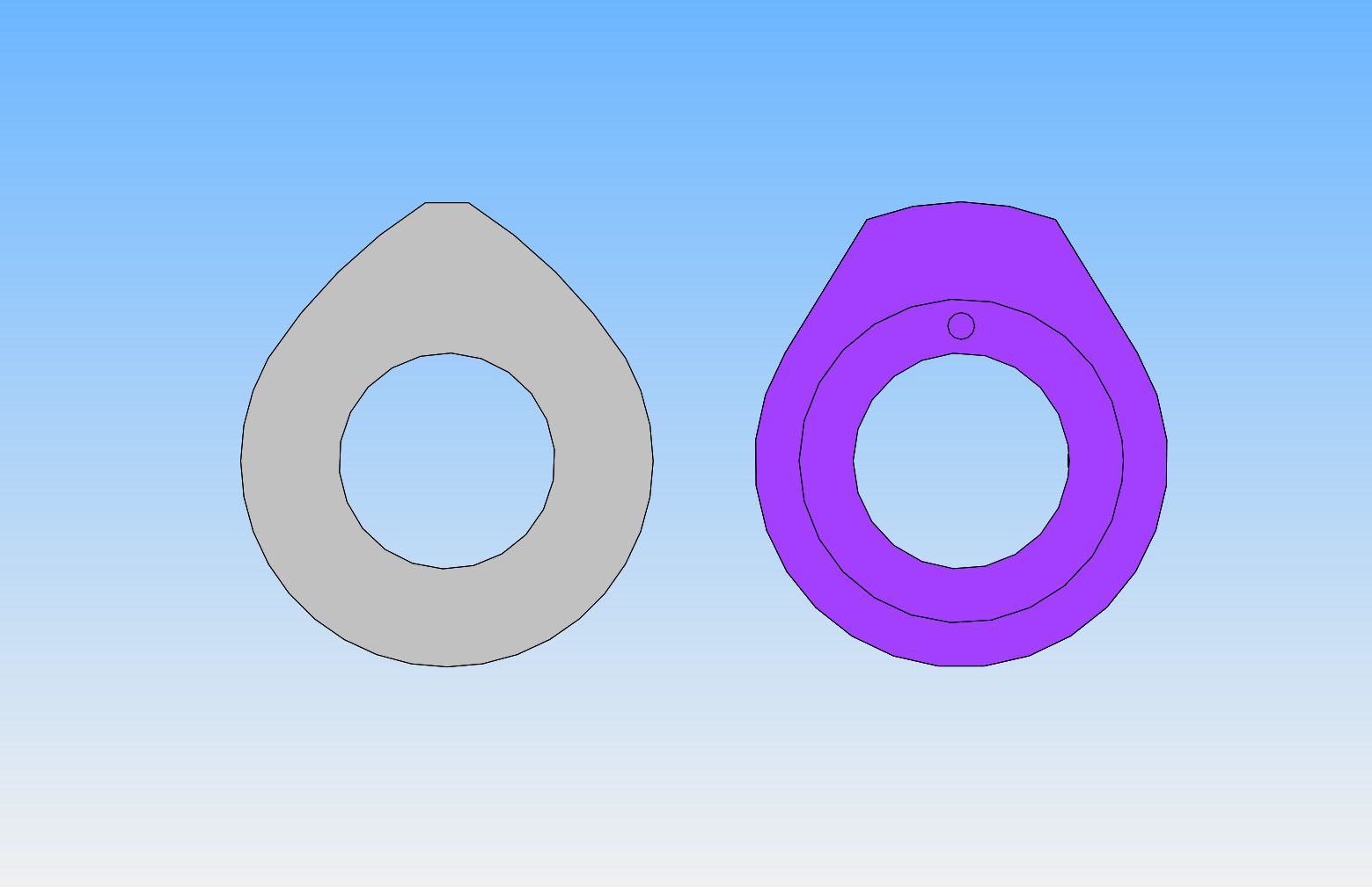
Before I go any farther with modifications to this engine, I have to right an old wrong. When I first built this engine 6 years ago, I had only built one engine before it, the Webster. I had a terrible time getting this engine to run at all, and finally, in a rather desperate move, decided that the cam design per Mr. Kerzel must be wrong. So---since I had great experience with the Webster, I decided to make a clone of the Webster cam to run in the Kerzel engine. As you can see from the attached picture, the grey cam (as per Mr. Kerzel) and the blue cam (as a clone of the Webster cam) are very different. Since I am head and shoulders back into this engine, I will make a new cam according to Kerzel's original plan and install it. The dwell on the blue cam, which I am currently running, is about 4 times greater than the cam designed by Kerzel. This has to be having a pretty radical effect on the engines performance, so I will make a new cam and install it before I do anything else.
 
Jim--What are you doing to give your exhaust a louder bark?

Brian,

I found a length of thin wall brass tubing that would just slip over the 1/4" copper exhaust pipe, cut it to about 3" long and cut a V slot about 3/16" down from the top about half way through then soldered a cap on the top. I think this makes the sound hit the top and then bounces out the V slot:confused: It does make the POP louder. I haven't soldered this on the original pipe yet so I am going to experiment with different lengths. Sure wish I had a CAD program so I could show how I did the extension but I think my explanation is fairly clear.

BTW I made my cam as per Mr. Kerzel's plans.

Jim
 
Tomorrow I am going to make a new cam, using the Chuck Fellows method. Chuck doesn't want to take any credit for this, saying he learned it from somebody else, but Chuck is the one with the youtube video showing how it is done. It is a really easy way to make a cam, once you get your head around it. If you Google "chuck fellows cutting cam" you can see a video of him doing it. I used that method on the cam for my oscillating i.c. engine, and it worked great. It gives a nice radius to the cam flanks.
 
So---Here we have the old cam on the left and the new cam on the right. The new cam has since been installed on the engine. I did use the method that Chuck Fellows shows in his YouTube video, and it works so well that I am going to start a separate thread on setting up a cam in a vertical mill to use that method. It is remarkably fast, and it gives a nice flank radius on the cam, instead of just flat sides. This is the second cam I have made using that method, and a large part of today was spent writing down all the "step by step" procedures in setting it up so that I could dial in the dimensions of the cam and not just take a guess at the flank radius being cut. It took me longer to write everything down than it did to machine the cam.
 
Brian, been using the same cam cutting myself
Here is the video from Chuck Fellows
[ame]https://www.youtube.com/watch?v=IEtqETL2LXs[/ame]

Cheers
Andrew

5.jpg


6.jpg
 
Brian,
The shape of the cam lobe can take on a different profile depending on what type of follower or lifter is being used. In the automotive world you can have a flat tappet cam lobe and a roller tappet cam lobe with the same timing specs but completely different shapes.
Another thing to consider when setting up the timing on a hit and miss engine is the adjustment of the rocker arm for valve clearance. Most of the hit and miss engines that I have built have a lot of valve to rocker arm clearance, not like regular cam operated I.C. engines. By changing the valve clearance, just like on a regular I.C. engine you can change the valve timing.
As far as flank radius goes, the purpose is to soften the contact between the lifter and the cam. Instead of the cam banging into a flat side it ever so slowly is accelerated into opening. Personally I have never built a flank radius into my cams and have never had a cam wear out even after hundreds of hours of operation. Here again when machining a cam with a flank radius your timing events are going to change because of when the contact between lifter and lobe occur.
For timing a hit and miss cam lobe it can be opened anywhere from 30-50 degrees before BDC. By then most of the work of combustion has taken place. For closing I always make it as close to TDC as possible. There's no need to have it close after TDC as in a conventional engine because the intake will only open when there is vacuum being created in the cylinder and the longer the exhaust is open the smaller the amount of intake charge will be created. On a conventional engine valve overlap is used as a way of drawing in the fuel charge by the flow of the exhaust as it evacuates the cylinder.
gbritnell
 
Thank you George. I knew most of that, but hearing it from a second source, especially from someone with experience is always a very good thing. Knowing my cam profile exactly, I may try working backwards from "closed at top dead center" to see exactly when I should start opening the exhaust valve.---Brian
 
Okay guys--stay with me on this. It gets a bit theoretical at times---. this is the cam, as designed by Kerzel. Using some cad magic, I "machined" the cam exactly as Kerzel advises in his original plans for the hit and miss engine. I then matched a circle to the resulting profile, and discovered that Kerzel had done his job very well.--the resulting diameter of the circle is exactly twice the base diameter of 0.6". The radius described by this circle is called the "flank radius". I then did a little more cad magic and see that the angle of "cam influence" is 122 degrees. Since the cam revolves at half the speed of the crankshaft, that 122 degrees actually translates to 244 degrees of "influence" at the crankshaft. As the piston moves from bottom dead center to top dead center, the crankshaft revolves half a turn which is 180 degrees. We want the exhaust valve on a hit and miss engine to close when the piston is right at top dead center, with no overlap, because the intake valve is operated by atmospheric pressure and will not begin to open until that exhaust valve is fully closed. So---we subtract that 180 degrees from 244 degrees. and this tells us that the exhaust valve should begin to open 64 degrees before the piston reaches bottom dead center on the power stroke. This does not take into account any "valve stem clearance", but that amount is very minimal when set to .005". This seems like an awful lot of "lead" on the exhaust valve timing.
 
Hi Brian,
That is a lot of lead on the exhaust opening but if the cam is made to the drawing a few 'fudge' factors could be used to reduce that number. One would be to increase the rocker to valve clearance. Now I'm not talking .032 or such but by adding another .005-.007 it will change the timing. Another would be to allow the exhaust to overlap TDC by 10 degrees. I know we talked about it but 10 crank degrees would hardly be noticeable.
I guess not being a mechanical engineer or never having delved into combustion processes that deeply I don't know how much energy is still in the cylinder at given crank angles.
Ok let's kind of analyze this as amateurs. Ignition timing is set to burn the fuel mixture and create maximum cylinder pressure just as the piston passes TDC. Fuel burns at a constant rate given octane rating and compression pressures so as the engine rpm increases the ignition advance has to increase to create the maximum pressure at the same point. Now once this pressure is created my question is how much useful pressure remains at say 30, 45 and 60 degrees of crank angle. On a multi cylinder engine the cylinder pressure would be less noticeable because there would be another cylinder creating energy but on a single cylinder engine at some point the cylinder energy would be wasted. Along with loss of work the exhaust would have a nice flame coming out of it due to the still burning fuel mixture.
I like you grew up with hot rods and engines and am pretty well informed on what a cam does to an engine's operation with changing numbers but like I said I don't know the physics part of the equation.
gbritnell
 
George--I am in the world of "try it and see" engineering. I'm sure everything you say is absolutely true. I'm sure that Kerzel was probably "right on" with his cam design, as many people have successfully built and ran this engine using Kerzel's cam design. I am trying to search out the mathematical reasoning behind some of the cam design as it realates to engine performance, and how the actual cam shape is determined, then how do we use our manual machines to best machine the cam and be able to end up with a cam that matches the parameters of the "design on paper". I had a crazy thought in the middle of the night. If I machine a piece of steel with the same thread and shoulder as the sparkplug, with a hollow center, then I can slip a piece of neoprene fuel line over it. Assuming that we want the exhaust valve closed when the piston gets to top dead center, we should be able to blow air thru that tube by mouth and have it escape right up until the moment the exhaust valve closes when turning the engine by hand. I know that both of my valves are sealing perfectly, so it would seem to me that as you turn the crankshaft by hand, you will know the instant that the exhaust valve fully closes, because you won't be able to blow any more. This will give a very good way to know that the exhaust valve is fully closing at the correct time in the cycle.---Brian
 
Finally, we are up and running again. I ended up with the exhaust valve beginning to open at about 50 degrees before bottom dead center and the timing very slightly advanced. Lord, it's been a struggle. I couldn't do the "blow down the sparkplug hole" trick, because although I have a 1/4-32 tap, I don't have a 1/4-32 die to make a fake sparkplug with.
[ame]https://www.youtube.com/watch?v=pZwJBjGehhs&feature=youtu.be[/ame]
 
Time to put this thread to bed. The video tells it all!!!
[ame]https://www.youtube.com/watch?v=H4gQ5R1oq94&feature=youtu.be[/ame]
 
Brian, The video comes up as "This video is private".
Just thought you would like to know.

Cheers
Andrew
 
It's time for the Kerzel to go back up on the shelf, but not until it's had a little work session. These little engines set around all over the place in my office, and the only time they get to pay any of the rent they owe me for the space they take up is when they get a chance to do a little work for me. The Kerzel is now paid up for the foreseeable future. You won't see it missing in this video, because it is working under "load".
[ame]https://www.youtube.com/watch?v=cW74MBUU2ZA&feature=youtu.be[/ame]
 
The inability to get a real good "hit and miss" action is making me twitchy. This is not a good thing. I have ordered a 1/4"-32 die to make a false hollow spark-plug and try my "blow down the sparkplug hole and see when the exhaust valve closes" trick. Damn, if Dick in Ohio can get his Kerzel running a Viton ring to hit and miss so well, I should be able to too!!! I did take 0.040" off both sides of both flywheels, and although it helped, it didn't help enough to satisfy me.
 
It's just my thinking and might be totally wrong, but I think it is likely the power of the engine which is the limiting factor of how many 'misses' you can get in a row. Basically, a bigger bang from the power stroke will impart much more energy into the flywheels and take longer to bleed off than a smaller 'bang'. So the problem is not so much storing the energy but making it. Again I could be totally wrong here, but in the videos you showed with your Kerzel running without the hit and miss lever, the RPM didn't seem all that high. I thought without the governor the engine would run extremely fast (like the Rupnow Hit and Miss does without a governor) as each hit makes a heap more power. With a bigger flywheel it takes more energy to accelerate it so a lack of power would mean less misses between hits, just like loading the engine. That's why I wondered about your valve timing initially but potentially it's the carb underperforming?
 
Al, I am inclined to agree with you. The cylinder is only a 3/4" bore, and it doesn't provide a lot of power when it hits. However, I do have a video of the same engine running a viton o-ring, and working exactly the way I would like mine to work.--Brian
[ame]https://www.youtube.com/watch?v=0mgjPH3B5KE[/ame]
 
Gentlemen,
Getting a hit and miss engine to run slowly is a balancing act. The more compression the engine has the more inertia it needs from the flywheels to get over the compression stroke. On an engine with good compression when you flip it over by hand it takes a good flip to accomplish this. Once that combination is sorted out then by fine tuning the springs on the governor the speed, or miss time can be adjusted until the compression issue reappears.
On any engine the power is going to be directly related to the amount of air/fuel that the engine takes in and on a hit and miss engine relying on the engine vacuum to open the intake valve isn't the most efficient means of accomplishing this. Again this is a balancing act of using a valve spring with just enough tension to close the valve effectively but not so light that it can't overcome the friction of the valve guide.
gbritnell
 
Back
Top