Half Scale Douglas Motorcycle Gearbox

Home Model Engine Machinist Forum

Help Support Home Model Engine Machinist Forum:

This site may earn a commission from merchant affiliate links, including eBay, Amazon, and others.

RManley

Well-Known Member
Joined
Jan 6, 2011
Messages
113
Reaction score
38
A few of you might recognise the subject title from another thread that I started about the engine of my bike project. Well, rather than bring that one back for the gearbox, I started a new one.

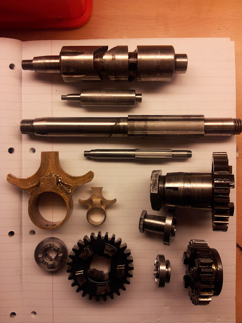
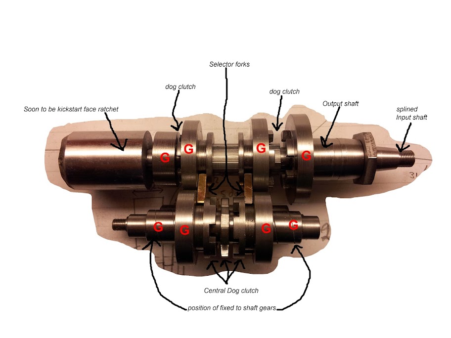
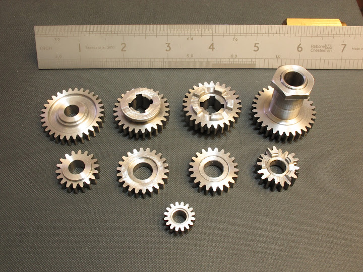
The whole reason I started this bike project in the first place is because the gearbox was locking in 1st gear - not very good in modern traffic that likes to punish those who hesitate! So, whilst taking the box apart, I started to measure bits and make parts.

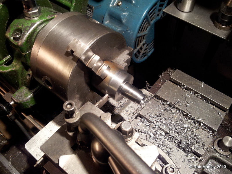
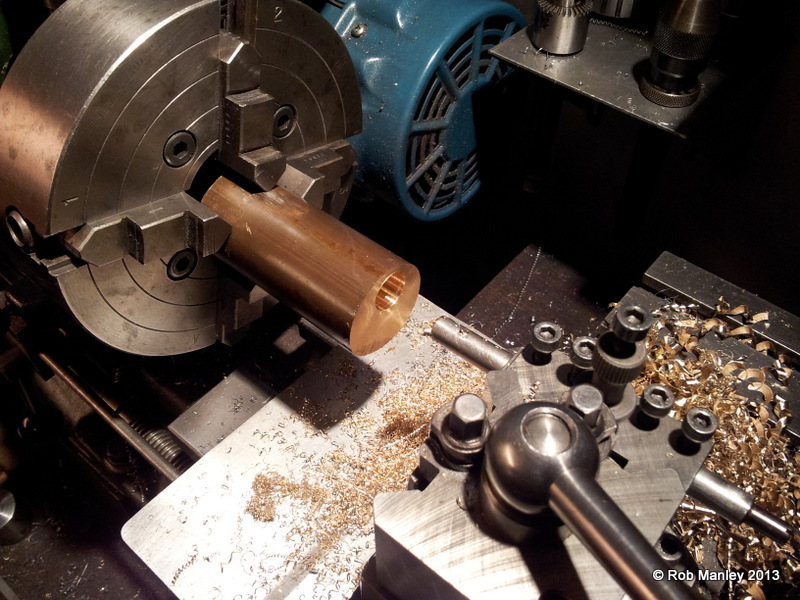
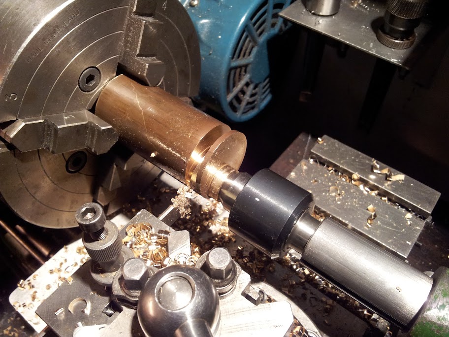
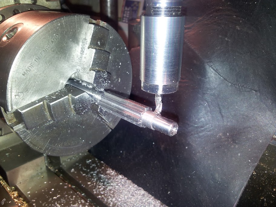
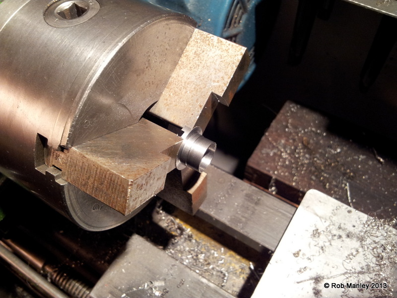
The first thing I started was the kickstart lever. This was fabricated from 2 pieces becuase the large 'end' has a tapered splined bore which was easier to do in the lathe when in bar form.
20120926_123944.jpg
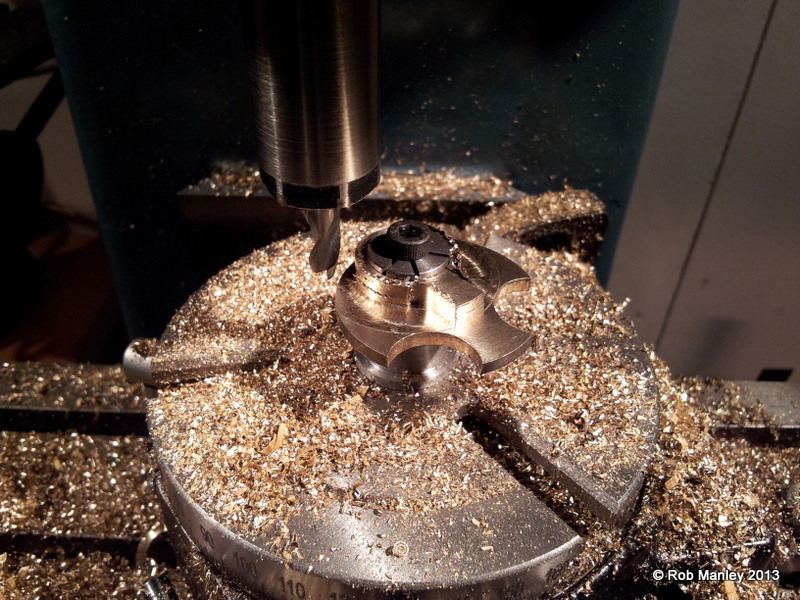
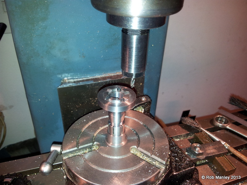
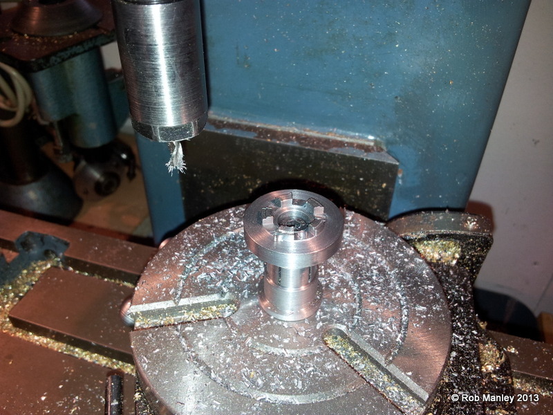
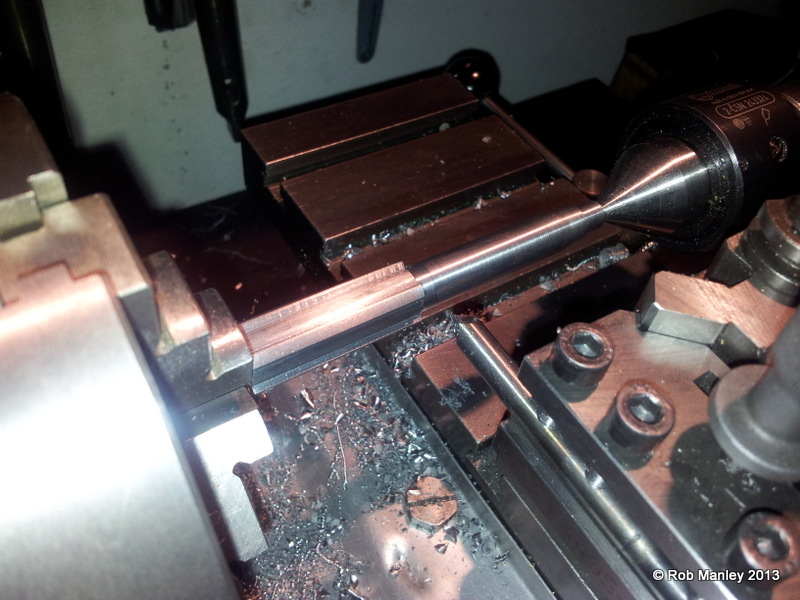
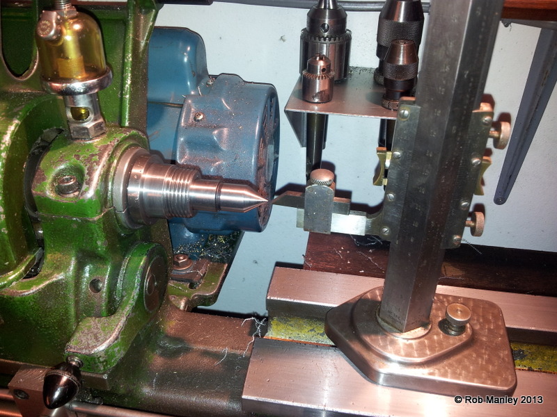
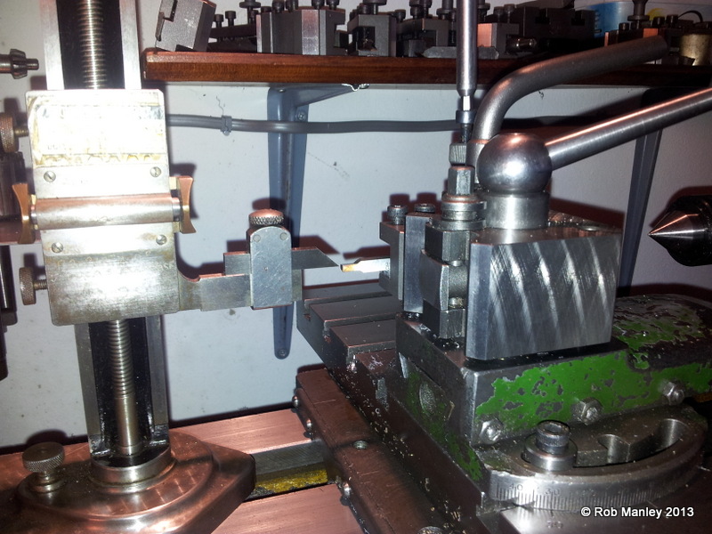
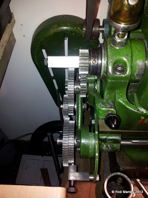
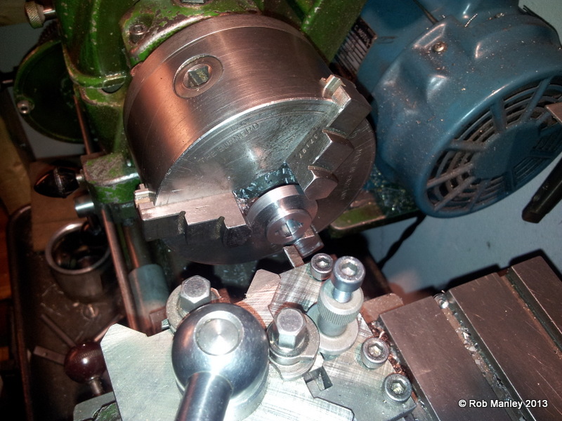
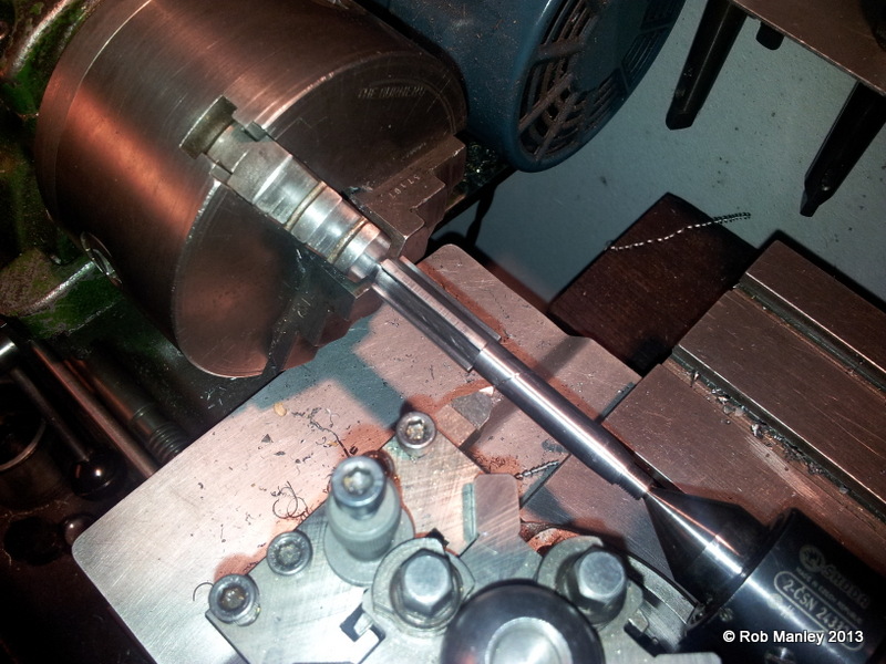
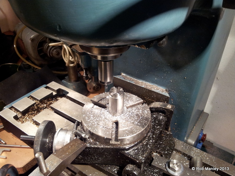
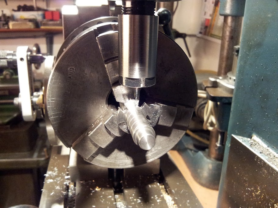
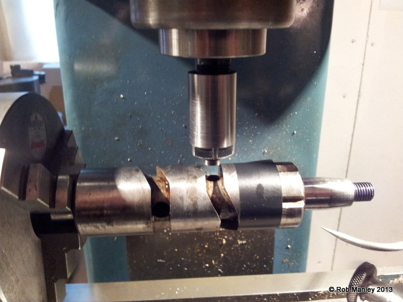
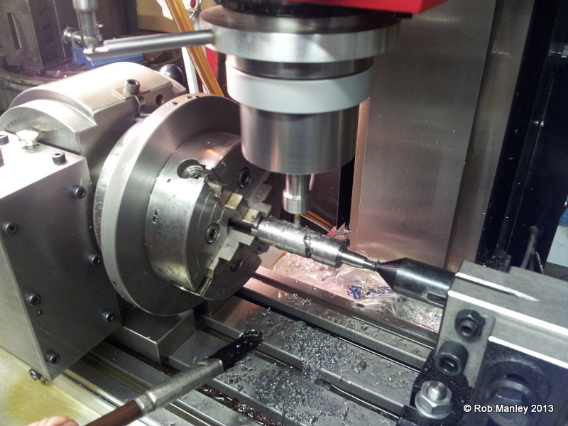
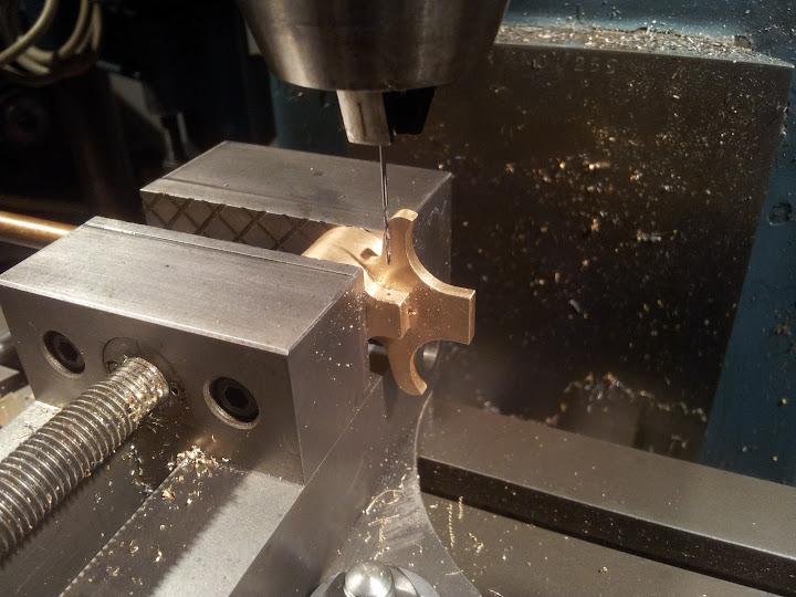
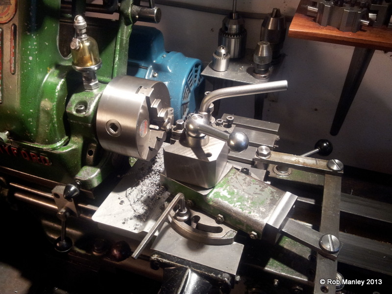
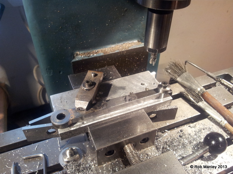
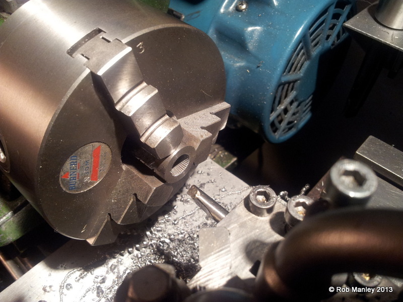
The setup for cutting the splines. The chuck was indexed using a pointer on the change wheels on the back of the machine. There are 40, 90degree splines in total.
20120926_123932.jpg

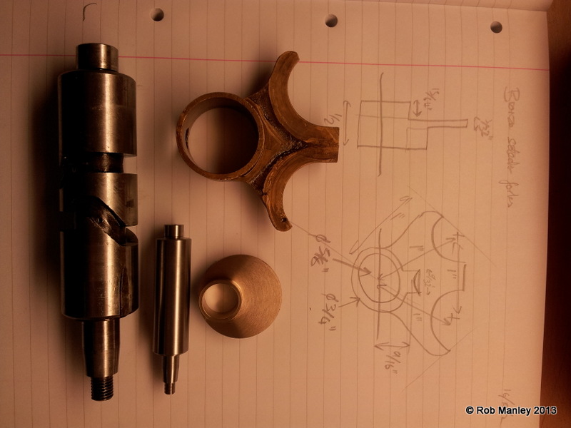
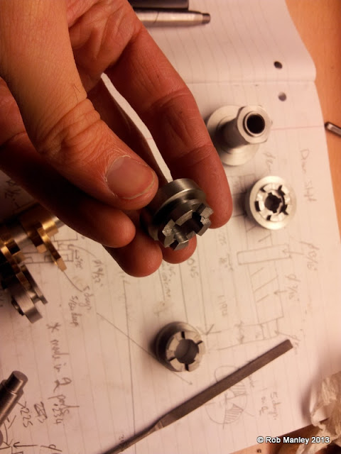
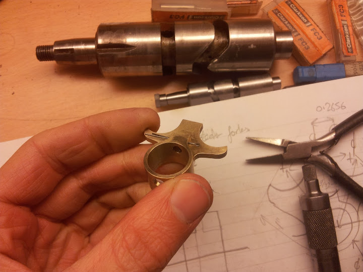
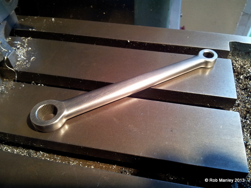
This boss was then silver soldered to the 'arm' of the lever and profiled.
20120926_145953.jpg

Then lots and lots of filing...
20120927_165250.jpg

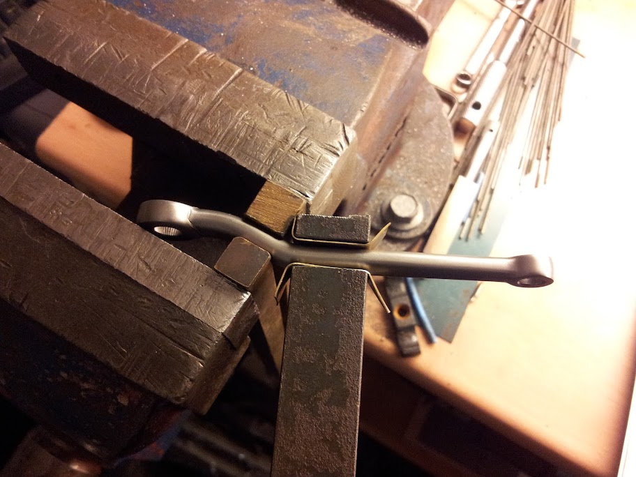
The kink was put in the lever using a 2ft bar and the vice. Not very pretty but it worked a treat!
20120927_172200.jpg

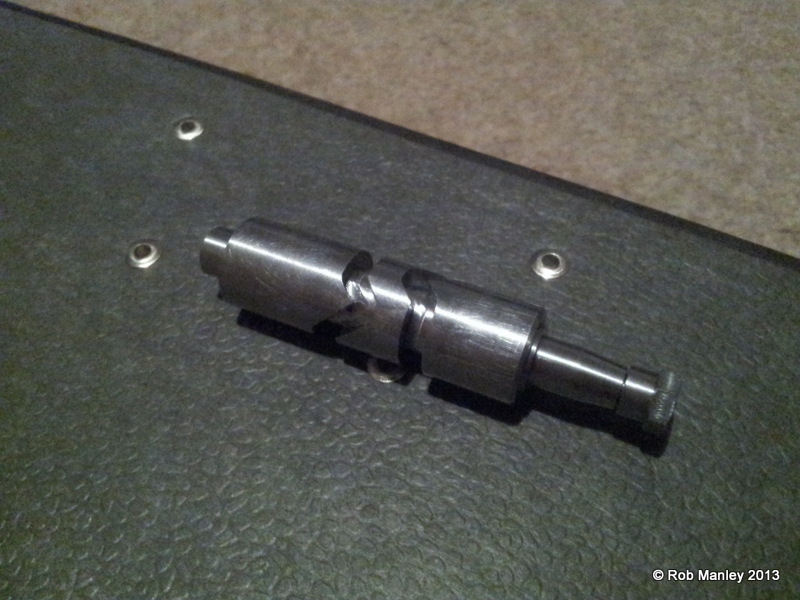
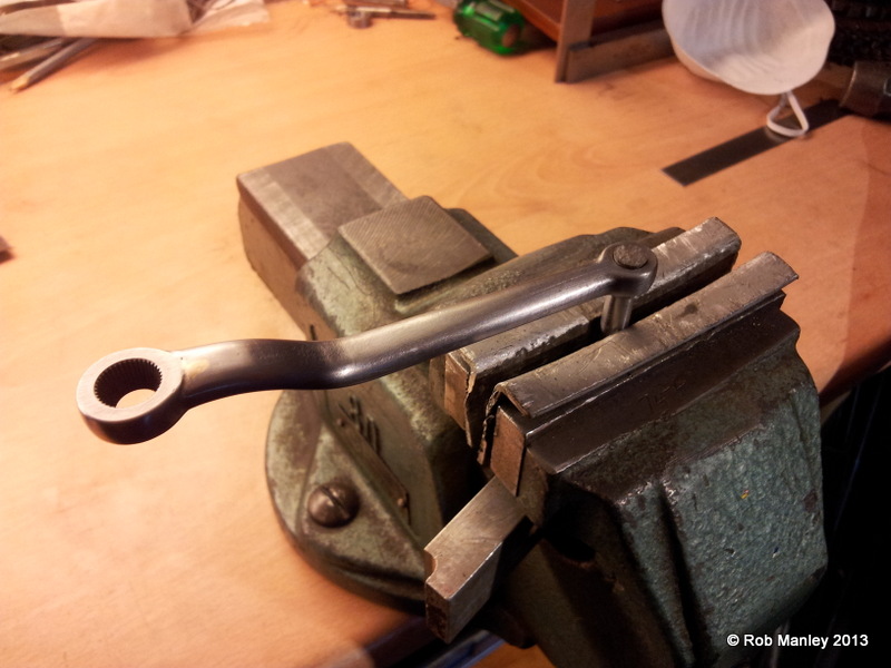
The peg was then rivited to the small end trying not to put any dings in it with the hammer.
20120928_111818.jpg

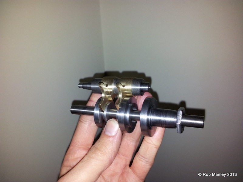
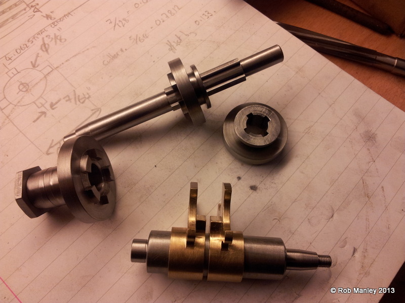
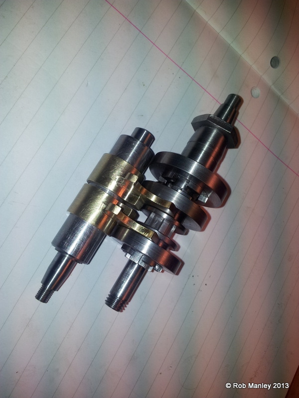
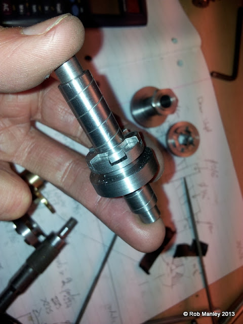
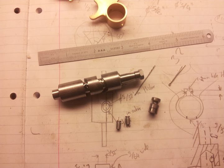
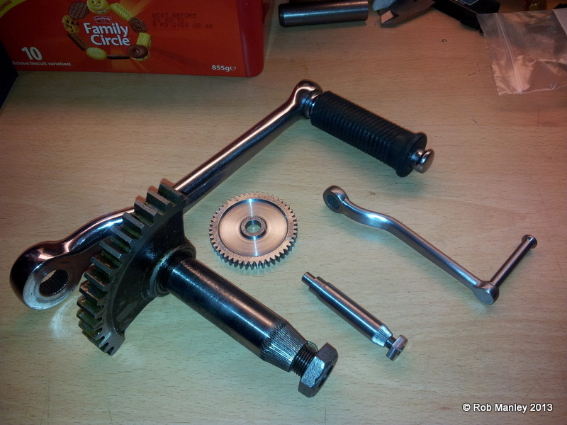
With its stub axle ready for its 120degree segmented gear, it looks quite good against the full size one! The splines on the stub axle were cut in the same way except the angle is slightly different to allow for the change in mating face diameters. I will have a go at casting all the rubber parts in one hit so that will have to wait a while.
20121017_183543.jpg


Rob. :)
 
Last edited:
Now for the gearbox internals. Luckily the pre-war designers liked to keep things easy, like the 2" centre distance from each of the three gear shafts. This made working out diameters and tooth numbers for each of the gears very simple. I've tried to keep the ratios the same as the full size but had to increase two to get the tooth numbers to work with the centre distance. All the gears are 24DP.

A friend with a gear hobbing machine has offered to cut the gears for me which saves me having to buy expensive cutters as I would need 4 different types due to the different numbers of teeth. This does mean that I will get the gears cut at the same time later on. This does me I cant try anything yet :(

The 4th speed wheel is ready to be parted off. The gearbox input shaft runs through the centre of this wheel and the drive to the rear wheel will be via sprocket on the taper.
20121013_195845.jpg

The hardest part of the gearbox to me, are the bronze selector forks. I couldn't believe my eyes when I saw what they were asking for a tiny piece of phosphor bronze so I managed to get the forks out of a piece that I already had. The amount of swarf I produced almost made my wallet cry.
First, bore the fork to fit my selector shaft diameter.
20121016_185102.jpg

Machine away what isn't needed, the outer face is final so it was given a good finish.
20121016_191811.jpg

Full size vs half size:
20121016_192136.jpg

Some work with a rotary table and an expanding collet later:
20121023_190616.jpg
This is what I have so far as of today:
20121023_202959.jpg

It doesnt look much but as with this hobby, its taken ages!
Im hoping to get a good days run tomorrow, get some more gear blanks made and start on the aluminium casing. The gearblanks have to have splines cut in them yet and a splined shaft making......:-\
Rob. :)
 
That looks great! Quite an ambitious project making a gearbox. I look forward to following along.

Lee
 
Rob, that's sweet!!

I love old British engineering, that's why I have a 65/72 Triumph Bobber (in the making) and a 76 Bonnie (Needs LOTS of work since I ran it into the ground ... lol ). I ride a 2005 Rocket III, but I love to tinker with my old Brits.

Of course they are not on par with a Douglas, but I like 'em all .... any ole British iron is gold to me :)

I'll be watching this build for sure!
 
Wow Amazing project
I love your work :)
Pete
 
Good to see you posting some more on this project, have you done much on the rest of it lately?

J
 
Hi Rob

Do I see an ML7 there. Great British lathe for making great British bike bits on (but I'm biased ' cos mine's an ML7 too)

I like your slotting arrangement for doing the splines, can you cut them in one go or do you need to take several cuts per spline. You could probably cut small gears like this but it would take some time.(and you'd end up with arms like Popeye).

Regards Mark
 
A great project - I look forward to the next installments.

I too am interested in your ML7 slotter. Can you give us any more information on it, such as overall sizes, maximum practical cuts etc? I would like to make one similar to yours.
 
I didn't get as much done today as I hoped. Things took longer than they should've etc. But, I cut the dogs on the rear of the gear blanks and started the input shaft:
20121024_111550.jpg

I have so little space under the cutter I have to use the expanding collet just to get the cutter in. I dont think this mill will be with me for very long, its not suited to what I do and need. Sadly, Im so limited for space I dont know what I could swap it for. 4th Speed Wheel (above), 3rd speed wheel (below)
20121024_121600.jpg

The input shaft was a simple bit of turning between centres apart from the splines. 4 Splines, 7/64 width, cut using an offset cutter in the dividing head. A ring was made a nice fit on the end of the shaft the diameter that the spline goes to (3/8 in my case). This allowed the offset cutter to just touch down on the ring to get its datum and make sure I dont go too deep.
20121024_200754.jpg

The final stage was to grind up a tool and plane the curve between the splines. This gives a tiny tiny amount of clearance between this and the gear as it actually locates on the splines not the diameter. This was done in the lathe winding the saddle up and down.
20121024_220031.jpg

Tomorrow I will get the splines cut in the gear blanks so I can see what it looks like.

I will also measure the slotting tool I made and post it. The depth of cut depends on the shape of the tool, keyways or small 90degree splines make a big difference. I was able to cut the tapered splines in one go but decided not to hoping to get a better finish.
I wouldn't recommend it for big jobs as you may bugger your topslide but for the occasional job it does a treat!

Rob. ;)
 
Rob, this is really impressive stuff - I am learning a lot from your setups. Could you elaborate a bit on the offset cutter to get the sides of the spline approximately right? I could guess how you did that but would be interested in the calculations you did to get the correct offsets.
 
Today some real progress was made. I dont have any more pieces to show BUT THEY ALL FIT TOGETHER! ;D

First job was to cut the 4 splines in the gear blanks. Only two of the 8 gears in the box are driven with splines which is a godsend because it took ages. I do now have the right arm of popeye and repetitive strain injury.
First things first, get the centre height of my lathe, it was 5 thou under the 3.5" centre height which I didnt think was too bad!

20121025_094513.jpg


After grinding up a tool the width of the slot to be cut plus 2 thou for clearance, the height gauge was raised by half the width of the tool and used to set the tool to the exact centre.
20121025_095007.jpg


To index the spindle, I used the gear train on the back of the machine. On a Super 7 the main gearwheel on the spindle is 60 tooth, so you can easily index using that, but on the ML7, its 59 :rolleyes:. So, I used the geartrain and set a ratio of 1:1 and had a 60tooth gear on my home made sprung plunger. To index a quarter turn you just roll round 15 teeth making sure you always turn the same direction and the backlash has been taken out.
20121025_131604.jpg


I took 1 thou passes to the required depth and it seemed quite happy.
20121025_131551.jpg


voila!
20121025_135733.jpg


The last thing to do was cut an oil groove where the plain bearing would sit for the 4th speed wheel. This was done by turning the chuck using the leadscrew set at the right ratio. As I have an 8tpi screw, I needed to set the train to 4:1 giving me 1/2" of travel per 1 rotation of the chuck.
20121025_153846.jpg


Im really pleased with how it looks now and the gear blanks slide nicely on the splines (I had to fettle the shaft a bit inbetween the splines to get clearance) with a max run out of 1.5thou. I thought they would be wobbling all over the shop.
20121025_154132.jpg

20121025_154326.jpg

I would say that I have about 30% of the box done. I had hoped to start the casing today but like most things, it never happened. Im going to try at some face ratchets soon and really test the cheap and nasty chinese rotary table I paid way to much for :rolleyes:.
Billmac, to cut the external splines I centrered over the shaft using a DTI in the spindle of the mill then offset half the width of the spline wanted plus the radius of the tool. Set the dial to zero and slowly worked towards that taking a light final pass at full depth to get a good finish. To get to full depth and not beyond, I tuned a ring the diameter of the root of the spline, slid this onto the end of the shaft and used that to touch down on. I only went to full depth on the last pass as the offset makes a difference on the depth as you are coming up a a curve. The waste between the splines was removed with a form tool and some cheeky filing.

Thanks for all your words of encouragement. Im now living with my girlfriend and although she tries hard, 'thats nice dear' doesn't always work :hDe:

Rob. :)
 
Hi JasonB, I have been progressing slowly with stuff but haven't found the time to update anything recently. I've been concentrating on my new job as a design engineer and have stayed away from the shop. What time I have spent has been taken up with trying to get my new mill in a fit state, im not that impressed really. I think I might end up with a sieg x3 for the next 3 years or so until I more into a larger house and can get my senior back.
But, I have spent a little time on the wheels. I now have 1 fully laced wheel. With a little fettling with a dremel (on my christmas list) I will be able to get the rim re-chromed!
20120920_150649.jpg


Hi 110samec, here is the other thread:
http://www.homemodelenginemachinist.com/f31/half-scale-douglas-motorcycle-11460/

Rob. :)
 
That is one very interesting project :cool:
I've often had thoughts of doing the same for my series 3 land rover :) but that would be a long, long way off
 
A little progress made. I want to get all the gear blanks finished so I can cut the teeth in one session but I get distracted easily and like seeing what the assembly looks like (doesn't everyone?).

I started on the two driven gears which slide on the layshaft and engage with a central dog. The diameter of the gears meant that the roots of the teeth would cut right through the larger diameter carrying the dogs so it has been made in 2 pieces and will be silver soldered together once the teeth are cut. A simple ring was machined for the main gear and this will have teeth cut into it. The dog clutch part will then press into the ring.

The dogs were the trickiest part, so I started them first. I’m beginning to really hate this rotary table with a passion. Its naff.
20121031_163024.jpg

Once the dogs were cut using the same method as before, I parted them off and held them in the soft jaws of my 3jaw chuck to machine the backs a press fit. There is a slight step in them so that the gear presses upto a shoulder and leaves the right amount of space for the selector fork.
20121103_162524.jpg

Next the layshaft was turned between centres to leave a 1/8" thick disk in the centre.
An oil groove was cut into both shanks using the method I described earlier (turning the chuck via the leadscrew giving a very coarse pitch thread)
This was then held in the dividing head and the dogs cut out by offsetting the tool half its diameter and cutting a slot 5 times around the ring then offsetting by the same amount the other side and cutting another 5 slots. The centre was filed afterwards. A gearblank was used to check that the dogs fitted and that there was a little bit of clearance.
20121103_170956.jpg

I couldn’t resist and pressed the ring and dog blank together to see what the assembly looked like.
20121103_164255.jpg

20121103_174611.jpg

This is the whole lot so far. As the teeth haven't been cut yet the blanks don’t sit properly but it’s looking ok.
shaft%2520layout.jpg


Rob. :)
 
Last edited:
Rob
I wish I had half of the passents you have shone. The build is not less than poetry or a symphany. Nice work, can not wait to see it finished.
Nelson Collar


You can't escape the responsibility of tomorrow by evading it today. May the Lord Direct Your Steps
"When injustice becomes law - resistance becomes duty."
 
Progress. I visited my friend over the weekend and used his converted cnc milling machine and dividing head to cut the slots in the cam. Not sure If I could've done this any other way using manual methods without some sort of profiling kit. The cnc really made it easy.

First I drilled the holes in the bronze selector forks to accept the pins which will engage in the slot on the cam. These are drilled 5/32 for a set depth and then have a 1.2mm hole drilled all the way through. This small hole allows you to push some wire down and remove the captive pin to disassemble the unit later.
20121115_162049.jpg


The next job was to accurately measure the original cam. This was done simply by mounting it in the dividing head and with a locating pin, writing down the amount of rotation in degrees between changes in direction + or - 1/4" about the zero datum in the x.
20121115_144936.jpg


Once a simple program had been written to copy this (halving the movement in x) then the new cam was set up in the cnc mill. A 3.5mm cutter was used to rough out the slot taking 30thou deep cuts per pass then a final 5/32 cutter was used to a depth of 7/64.
20121117_160437.jpg

It came out really well. I hope the poor rack that will have to turn this will survive as the mechanical disadvantage in this system is quite large. There is a point on the original cam which has been welded back on as it was forced. Im half tempted to case harden the cam a bit later on. I will be using silver steel for the pins as it should be fairly hard wearing.
20121118_195256.jpg

I then drilled the selector forks to take the split pins. These holes break through into the hole that the pin sits in.
20121119_161854.jpg

A 0.85mm drill was used.
20121119_162954.jpg

The pins have a groove cut which the split pin sits in to hold it captive.
20121119_171934.jpg

Assembly: There are two holes in the cam slots that are there to drop the pin into, you then slide over the selector fork and push the pin up into the hole in the selector fork using the 1.2mm cross hole drilled through the cam. A split pin is then pushed though the boss on the selctor fork and locates in a groove in the pin holding it captive. The cam can rotate about the fork with pin suspended in the fork. To disassemble the cam you remove the split pin, using a paperclip through the 1.2mm top hole (see first pic) push the pin into the holes drilled in the cam and slide the fork off. Confused? :D

Also, the gear blanks are having their teeth cut so I should have a fully functioning 'cluster' before the end of christmas. Only the case to worry about now ;)

Rob. :)
 
Last edited:
Rob, this is looking better and better all the time. Can't wait to see the finished article ....
 

Latest posts

Back
Top