Half Scale Douglas Motorcycle Gearbox

Home Model Engine Machinist Forum

Help Support Home Model Engine Machinist Forum:

This site may earn a commission from merchant affiliate links, including eBay, Amazon, and others.
Hi Rob

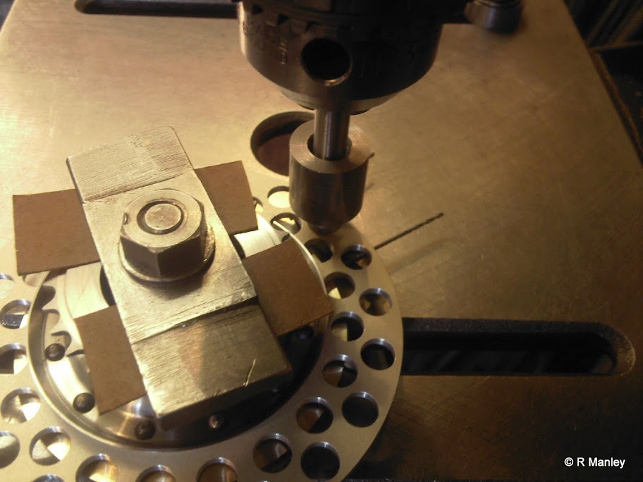
This is looking more and more impressive all the time. Drilling the split pin holes looks tricky 0.85mm through bronze (drill grabber at the best of times), quite deep and intersecting with the side of the pin hole sounds like a perfect recipe for a broken drill without extreme care. Awesome mate.

Regards Mark
 
I took a few days out of studying to play with the gearbox. The teeth have been cut on the gears and I can now start turning up bronze bushes and silver soldering gears together where required. I have to thank my friend for the great job he has done cutting the teeth. :)

To finish off the gear cutting, a rack was produced from gauge plate for the gear change mechanism. This rack drives a 16tooth sprocket on the end of the cam. This was done in the vertical mill using a special jig.
IMG_0093.JPG

IMG_0095.JPG


I've started on the case itself. I made a 3D model to check all the sizes and to make sure I can fit all the gears inside - its going to be a tight squeeze. The case is going to be milled from a block approx 2.25" cubed. I decided to bore the most of the metal away on the lathe but before that I drilled all the holes for the cover and milled a guide on the CNC mill 1/32 deep so I knew where to bore upto.
20121205_112005.jpg
This also allowed me to accurately make a center mark in the position the bores relative to the bolt holes.
20121205_121618.jpg

This took ages due to the intermittent cut when the bores broke into each other but it finally looked like this:
20121205_154614.jpg

The remaining pillars of unwanted metal inside the box were removed by plunging a cutter down as close to the edge as I dared.
It was then put back in the CNC mill and its outer end profile cut. The wall thickness is about 1/8" at the thinnest point.
20121205_190623.jpg


This is as far as I got before I ran out of time. How will I get all this into the case?
20121206_152634.jpg

20121206_153059.jpg


Rob. :)
 
Hi Rob,
Wonderful work on the gear box. It brings back memories when I was making my T-5 a couple of years ago. Are you planning on using a clutch with friction plates? If so, what's your plan for them?
gbritnell

GEAR SET 3.jpg
 
Well George it was your gearbox that made me think it was possible in the first place.
It's a crash box with the cam moving a pair of gears along the shafts to engage the dogs. The clutch is in flywheel as in the pic below.
SDC10152.JPG


fingers crossed it works!

Rob :)
 
Last edited:
Rob, do those cork pieces go right through and are replaceable?

Very nice work with the clutch, I can see no reason it won't work as it does on the full size machine.
 
Hi Mark, yes I was quite scared about drilling that hole. I plugged the hole that the drill would intersect with using a piece of brass to stop it wandering and that seemed to work quite well. I suppose I shoud've really plugged it with bronze but I got away with it.

The workshop was at 4°C or 39F today andwasnt getting any warmer so I didn't get much done.
Im replacing my milling machine with a seig X3 super which has the height under the quill that I need so I spent the first hour tidying that up and taking photo's.

In the second half of my stint I had a closer look at the rack for changing gear (see pic further up). Half of its length is turned down to its thickness which then protrudes through a bush in the top of the gearbox so that it can be pulled up or pushed down to change gear. The full size one is nicely made with the diameter only 2tenths down on its thickness (1/4") but not a single hint of a flat along its length.

The gauge plate rack was made approx 1/4" too long to allow for dodgy starts of the die and putting in a centre. The rack was then clocked up in the baby four jaw chuck and centre drilled.
20121208_135419.jpg

This was then pulled out and clocked up again. It was then turned to 1/8" diameter along its length making sure not to squash the job with the live centre.
20121208_143351.jpg

Being gauge plate it didn't deflect much and with a light final pass I could detect no change in diameter. I then realised that I had no 1/8" whitworth die and it was still 4°C so I came in.
20121208_181655.jpg


Hi Andy, yes those cork pieces go right through and were pushed in wet upto a stop in the drill press.
SDC10193.jpg

Once the cork had dried, the plate was held in the lathe and using a dremel, skimmed flat. It worked suprisingly well!
Photo-0036.jpg


Rob. :)
 
Last edited:
I have finally finished a month's worth of uni exams so as a treat I spent a day in the workshop.

before I can continue with the case, I need to know the lateral gear spacing on the three shafts so I know how deep to hollow the case out for the outer bearigns. This meant starting the intermediate plate where all the shafts 'hang' off. This was the perfect job to test the new mill on.

A simple bit of peppering the plate with holes to drill through later. It took a while to make sure the backlash was in the right direction as my datum was in the middle of the plate (I wont be making that mistake again)
20130201_111959.jpg


This was then set up in the myford ready to have the bearing bores machined. Its easier to do it this way than try and machine accurate bores & faces on the mill.
20130201_115900.jpg

The result is that im nearly ready to hang the shafts off the plate and do some measuring. Sadly this highlighted the issue that I have machined the slots in the cam cylinder too close to one end meaning making a complete new one :wall:
20130201_160551.jpg

And although slightly mal-alighned at the moment the gears drive and I can get the different speeds!

[ame]http://youtu.be/6QWv_ohHNMc[/ame]

I really need to get my machine CNC'd so I can continue without having to visit other people :rolleyes:. I think that maybe the summers job once I graduate (Please God make it happen sooner)

Rob. ;)
 
Rob

I continue to be amazed by this project; thanks for keeping us updated on your progress.

Dave
 
I just saw the cork clutch photos. Cork is what I use in my full sized 650cc motorbike. It's interesting that it was the standard material for it, with advantages of superior grippiness (coefficient of friction), inherent shock-absorbing quality, versatility (can be used wet or dry), and low cost. It's not popular now, because it burns if the clutch is abused by excessive slipping. Lots of impressive smoke! But treated nicely, I have no problem with cork, even when hauling a heavy sidecar.
I use an angle grinder mounted in the toolpost for grinding.
Rather than just wetting the corks, I put them in boiling water for a few minutes. That makes them temporarily very easy to squash, to fit into undersized holes. Then when dried, they are very secure.

Jordan
 
Nice work Rob, error or not. I can't wait to see the finished article ...
 
Hi Rob.
Amazing work:) Do you have updates on the buildlog?
CS.
 

Latest posts

Back
Top