Half Scale Douglas Motorcycle

Home Model Engine Machinist Forum

Help Support Home Model Engine Machinist Forum:

This site may earn a commission from merchant affiliate links, including eBay, Amazon, and others.

RManley

Well-Known Member
Joined
Jan 6, 2011
Messages
113
Reaction score
38
Hey all, I found this forum through the model engineer magazines website and it has stolen hours from me. There is some really amazing stuff being produced on here and im jealous that I cant produce stuff like i've seen here.

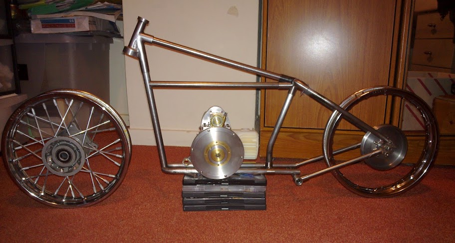
A bit of background before I describe my project, I like anything with character. So, when I had the opportunity to purchase a friends 1930's douglas motorcycle I leapt at the chance - even though I didnt have a bike license then! I restored it, rode it and now I dont have the time and the gearbox needs fixing so its been in the garage in bits for a while. It didn't take me long to think that a model of the bike would be nice. A complete one, not just the engine. So, thats where it started, a single offcut of aluminium and an old crankcase from a dead engine. 3D cad was used to model everything and some parts were machined on a home-converted cnc mill using Mach3 software. Everything else was machined on a ML7 lathe, Tom Senior mill or a friends Super 7 or colchester.

I have a website which is updated when work is complete and descriptions are added when I can. It can be found https://sites.google.com/site/halfsizedouglasmotorcycle/. Say Hi :)

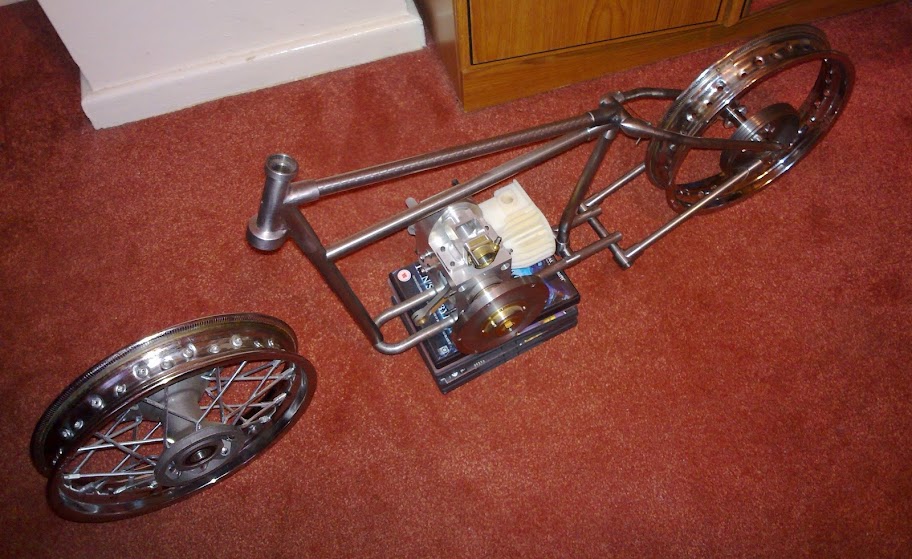
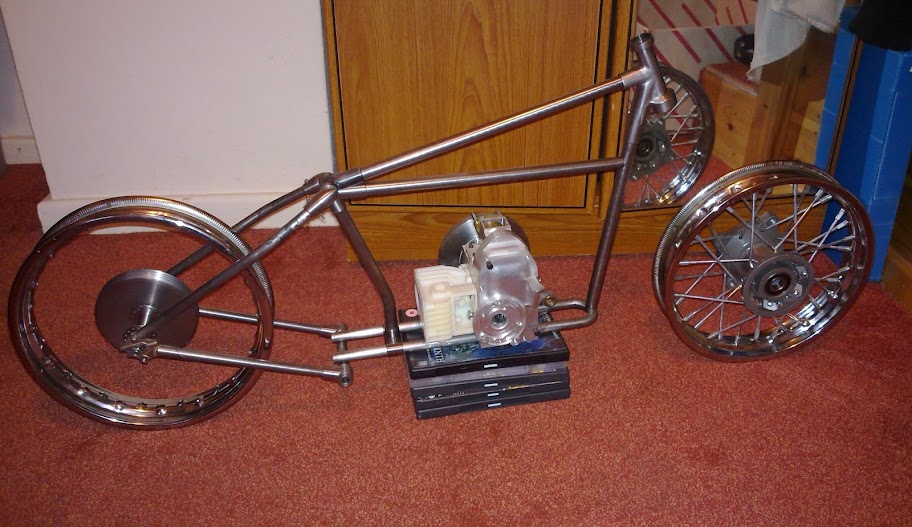
As others have done I will post photographs on here with short descriptions. Hope you like it.

Crankcase:

A 3D model was made my measuring the full size crankcase. It's so easy when you have something to turn over and look at.

Fullscreen%20capture%2001082010%20181343.jpg


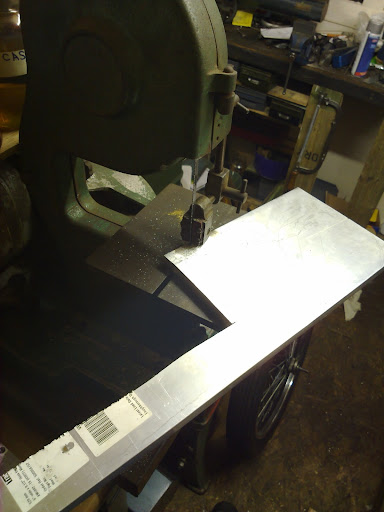
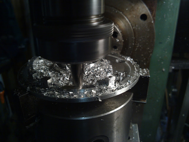
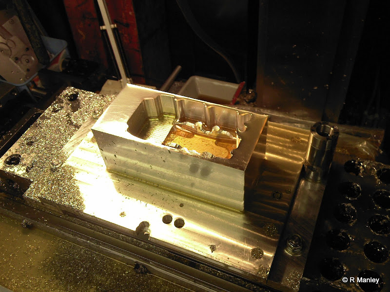
The block was milled square on the manual and then bolted to the raised aluminium table. The timing case was rouch machined using 1.5" long 1/4" dia ball end mills. It took hours - and just because it was done on the cnc doesnt mean it wasnt scary!

Photo-0045.jpg


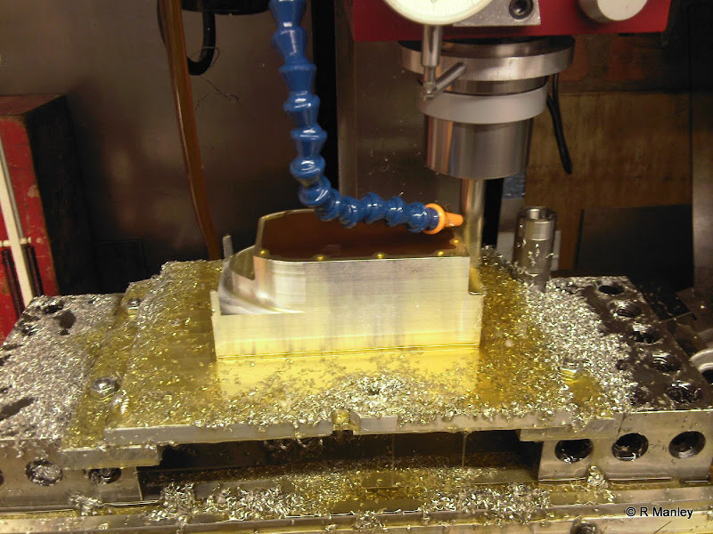
Profiling the top arch. This had to blend with the already machined sides....

Photo-0002j.jpg


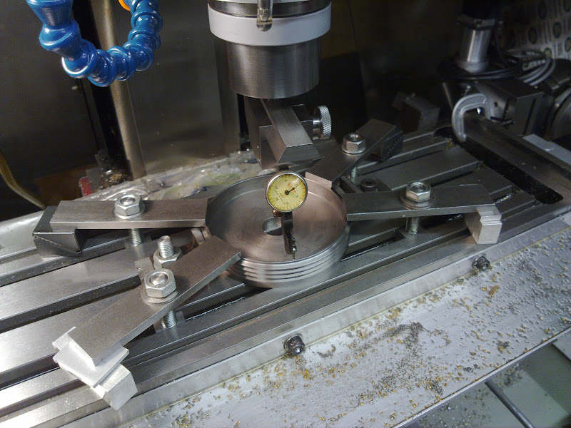
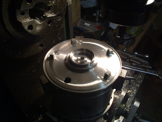
The tapped holes on the first face were then used to accuratly bolt the block upside down to machine the back without losing the datum. The tapped holes were M3 and by having almost no clearence on the matching holes in the raised aluminium plate, the block was less than half a thou off datum!

Photo-0003j.jpg


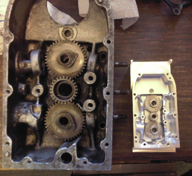
The crankcase plus cam gears next to the full size dead engine.

Photo-0004j.jpg


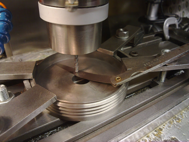
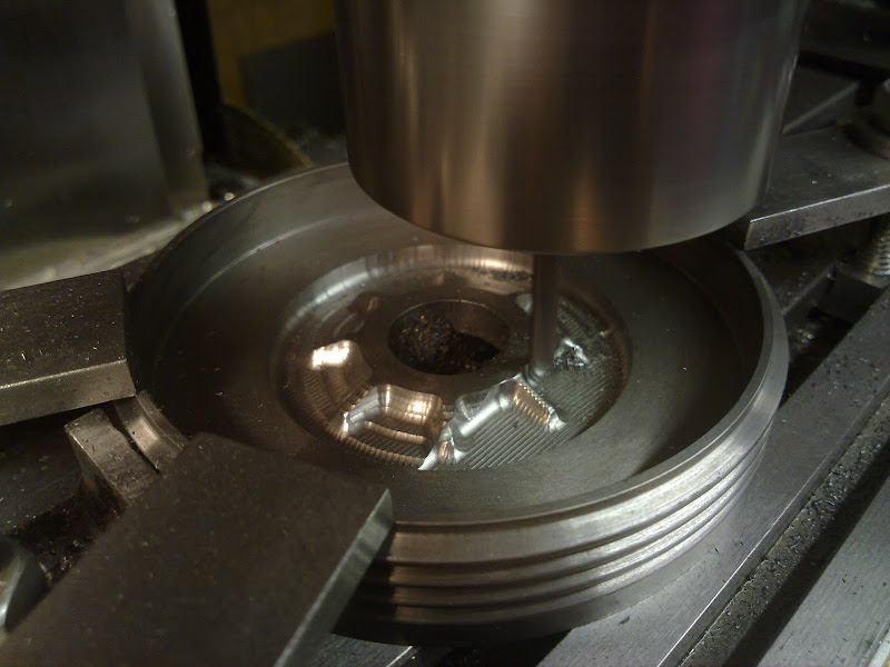
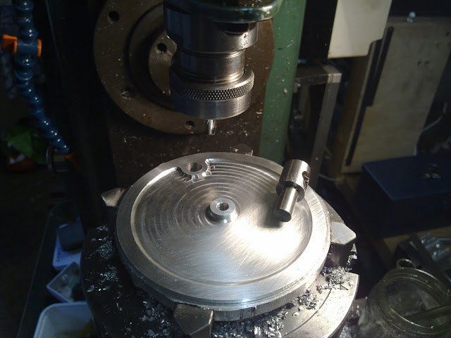
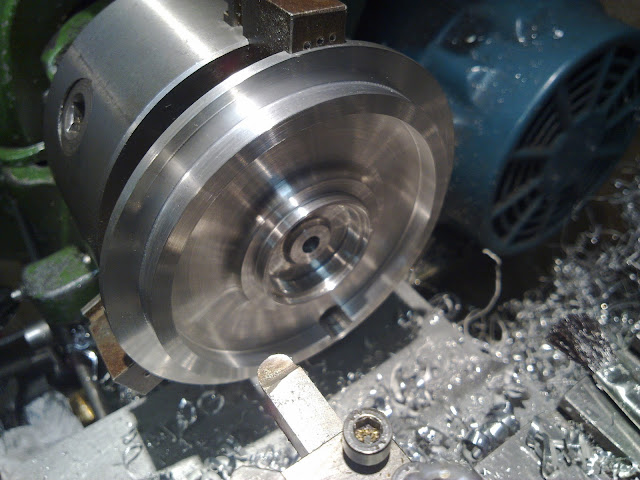
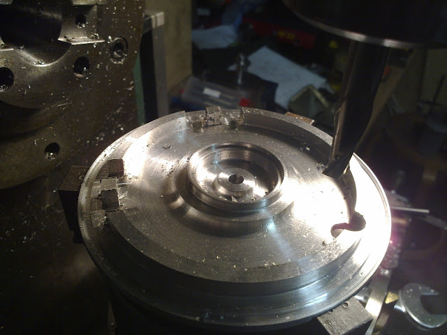
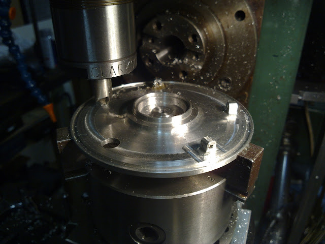
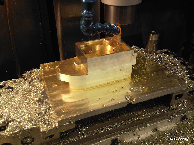
Machining the 'inside' of the crankcase

Photo-0006.jpg


Welcome to the forum RM. Some very nice work you have done there.

Another nice to build to watch for sure.
 
We welcome all who share the same disease. 8) Looking forward to this thread as thats very interesting work.
 
RManley

Hi and welcome to HMEM. That is an incredible job of machining that you have done on the block of aluminum. It looks like you will find a motor and transmission hidden in there by the time you are done. Thanks for showing us and we look forward to seeing more as you progress. :bow: :bow:

Cheers :)

Don

 
That's beyond my abilities. Do you have a picture of the motorcycle?
 
If you didn't look at his link, you're missing out! Excellent.

Greg
 
Here are some pics of the full size bike :)

The day I purchased it (was 16 at the time)
Copy%20of%20CCF17012010_00013.jpg


Outside my local model engineers club
291.JPG


In my garden after a slight refurb
DSCF1050mod.jpg


So thats what it will look like when finished just half the size ;D

And as a teaser here is an exploded view of the flywheel clutch

SDC10153.JPG


RM
 
Very interesting project Rob. I look forward to following this one

Steve
 
Very cool. I will be watching this one.

Fixed your img tags in your last post.

Eric
 
Hey all, I'm back at uni now until Easter so progress has pretty much halted, but I will show what has been done so far, so expect a picture heavy post. Progress over Easter included machining a tapered spline onto the front and rear hubs and the machining of the front brake drum.

The first thing to be done was to work out a way of planing the splines onto the taper of the hub. This is as per full size and I couldn't resist having a go. A useful feature of the myford super 7 lathe is that the large backgear is 60t allowing it to be used for division. A plate was used to index the spindle and by chance, 60 splines worked out well.
Now, if you have a 10° taper, and you wish to machine splines on that taper you cannot just machine then at 10°. Due to the taper, you are trying to machine the same number of splines over differing diameters so, in effect the crests of the splines would be wider at the top of the taper than the botton due to the larger circumference. So, a 3D model was made and some calculations made to get a rough idea of the required angle.

The tool used to plane the splines was my modified ML7 topslide, the feed screw removed and some pivoted levers made. Its simple, works well, and provides a good way of setting the angle. Before people cry out 'poor little topslide' It rarely gets used this way and is the same construction as the cross slide which gets used so much more!

To get the angle perfect, some test splines were cut in a test blank at differing angles to get the crests (or the remaining uncut parts of the taper) parallel:

07012011926.jpg


The aluminium collet I made to finish the hubs was brought into action once more to hold the hubs for planing. The rear spoke flange is pressed up against the face of the chuck to take all the cutting forces. Due to the taper pretty much butting right upto the thread and the spoke flange various stops were required, these are the block of wood which is against the tailstock and the clamp on the front of the cross slide. The saddle stop is locked in position so that the saddle can be moved out of the way and returned back to the same place so not to disturb any settings.

07012011930.jpg


Thou cuts were made to a depth of 21thou before going onto the next spline, and approx 45 splines later, it looked like the photo below. A final pass was made without adjusting the depth of the tool taking them to 22thou. The tool used was a 90° tool with plenty of undercut sat on its side.

07012011933.jpg


With the finished result being:

07012011932.jpg%20target=


Now, the mating spline cut into the brake drum must have its internal taper machined to the trough of the spline, so, the repaired 2MT scope came into service. Centering the end of the hub vertically in the mill, then focussing on the trough of a spline, setting the dial to zero and focussing on the opposite spline gave me the core diameter for the drum.

11012011941.jpg

 
Very ambitious project RM but some beautiful work done already. I will definitely be following along for the half scale "ride"

Regards,
Bill
 
Brake drum
The cast iron billet was purchased at the Midlands Model Engineering Exhibition using some of my student loan money, so at least you know some of it is going on something useful. The 3 jaw chucks did not have the holding capacity for this 4-3/4" diameter billet, so the 4 jaw chuck was used and roughly trued by bringing a tool up to the edge when slowly rotating it. The billet is no where near round to start with and due to its size, the top speed used will not be sufficient to cause any issues with vibrations. Tungsten Carbide tools which are suitable for cast iron are painted red. This is not saying that tools not painted red aren't suitable as I'm sure some will be, but for instance, tungsten carbide tooling brazed onto a mild steel shank painted gold are designed for steel.

26122010912.jpg


The ML7 does not have any power feeds and so it took quite a long time on top back-gear to remove the amount of material shown in the photo. This is roughed out to a stage where it is worth sharpening your tools for finishing cuts. A diamond or green grit wheel should be used. If you don't have any of these (which I don't) then someone at your local club will. To ensure that everything stays running true, the billet should not be removed from the lathe.

27122010913.jpg


Next the cooling fins were machined. These were done with a HSS tool similar to a large threading tool with a rounded nose. These were cut in the same way as threading should be performed, with the topslide rotated through a tad less than half the form angle and any feed being put on using this. The cross slide should be used to retract the tool and then replace it to a pre-determined point. This means that you are only ever machining on one face of the tool (it is a very deep groove after all) and that the other face is lightly cleaned by the nose of the tool. There seemed to be a slight tough spot just where I wanted to put my fins, so slowest back gear, then using the spindle handle, slowest speed by hand, then slowest speed by hand + cutting oil gave a chatter free finish!

04012011915.jpg


The machined drum was then parted off, held in the 3-jaw and its back machined flat. Oh and I was able to part off the 4.5" diameter cast iron drum all the way through :) on a 40 year old ML7!

04012011916.jpg


The next stage was to machine the internal webs that would've been cast in. So, a 3D model was made and the mill switched on. A dial gauge was used to centre the drum.

07012011922.jpg


The tool given some clearance

07012011923.jpg


Then the machining starts (it isn't as easy as that as you know)

07012011924.jpg


Slowly takes shape into

07012011931.jpg


The rear of the hub was machined hollow as per the full size and the tapered bore machined to the size found earlier.

12012011942.jpg


The previous set up for cutting the splines was reassembled and the process repeated. The hub was used as a plug gauge, with half a thou taken off to get it to sit at the right depth. The tool used was similar to that used previously except in boring tool shape.

12012011943.jpg

12012011944.jpg


Now the internal 'cast' webs are finished, they will require blending into the 6.5° internal taper of the back face and some filing to remove the nobbles. A final skim of the brake surface is also done. The thickness of the rear face is approx 90thou.

12012011949.jpg


Voila!

12012011950.jpg


Thats progress so far.....

Now it is sat in my uni room and I can't do anything :( I have taken a few pics just to show progress. It is sat on standard size DVD boxes. The front rim is as purchased and not yet modified. The only thing missing in the picture is the carb which I cant attatch yet but can be seen on my site.

Happy machining folks :D

19012011970.jpg

19012011971.jpg

19012011972.jpg

19012011973.jpg
 
Amazing work! :bow: :bow: :bow: :bow: :bow: :bow: :bow: :bow:
My other 'hobby' is restoring vintage motorcycles but you`r making one from scratch!
Unbelievable!
 
that is the freaking coolest project I've ever seen!!!
Hats off Sir!

Bookmarked the thread.

tom in MA
 
Hey all, I haven't done too much recently as uni has taken up most of my time :(

Still, one of the technicians in the workshops kindly donated a piece of scrap aluminium 1/2" thick and large enough to just about get two 4.5" circles cut out of it. So, I drove home for the weekend with a plan to get the aluminium brake shoe carrier/cover started. I had to leave early sunday, so I only had saturday. This is it for another 5 weeks

My trusty bandsaw - very small but because of a countershaft intermediate drive can go through 1/2" aluminium plate without too much difficulty.
180220111049.jpg


The rough cut plate was then chucked in the 4 jaw and the initial faces skimmed flat and smooth
190220111050.jpg


The vertex dividing head is probably the most praised tool in my workshop! The ability to remove the chuck from the lathe, use it on the dividing head, then replace it on the lathe is invaluable. Throughout this process it was never taken out of the chucks afte initial set up. After the head was set up vertically and centered about the spindle the brake lever hole was drilled 3/8" using progressive drills and then a new 3/8" slot drill. A top hat plug was then made to fit the lever hole as a guide for the front recess.
190220111051.jpg


A specially ground (a 10mm slot drill with an 1/8" radius hand ground on the corners) was used to recess the front face about 50 thou.
190220111052.jpg


Using the guide as a stop.
190220111053.jpg

190220111054.jpg


The top hat bush whas then reversed, held in the chuck and replaced the 4 jaw in the vertical dividing head. Note the previouslly machined thread.
190220111055.jpg


A nut was made and the cover plate fixed onto the spigot. A 1/4" ball nose was then used to clean up the edges around the lever hole
190220111056.jpg


R.

 
The next stage is to do the rear of the plate. This has a few protusions and some steps.

The soft jaws were machined to accept the reversed plate. An old outer race was used to lock the jaws during machining.
190220111057.jpg


After alot of faffing, the rear looked like this:
190220111058.jpg


The chuck was then removed from the lathe and then screwed onto the already set up dividing head. After setting the lever hole in the y-plane, the chuck was accuratly rotated and offset half the width of the protrustion.
190220111059.jpg


An end mill was then used to remove the unwanted material between the protrusions by rotating the dividing head like a rotary table in the same way as the front was done. great care was taken to try eand get it to blend as much as possible with the previously turned face.
190220111060.jpg


The result:
190220111061.jpg


The bonus of the vertex dividing head - it was brought down to horizontal without altering any settings to drill and tap the shoe-adjustment screw holes.
190220111062.jpgg


Then as an afterthought, it brought back up vertically and the corners rounded with a 3mm radius cutter I didnt know i had.
190220111063.jpg


It is still not finished as I ran out of time - just the webbing in the centre to finish.

Results vs original:

Front
190220111064.jpg

200220111068.jpg


Rear
190220111065.jpg

200220111067.jpg


I hope you can forgive me for not including the shallow recess in the rear :p

Thats all for now, Robl
 
Looks real good. And that was a heck of a gift you got, a chunk of aluminum that size goes for a pretty penny.
 
Ooh Ooh and i got a parcel today :)

it was a piece of corian - pink corian to make a pair of LODGE spark plugs from. Sadly the colour isn't pink enough :(

So, ill have to find some more.....D'oh

210220111071.jpg


the spark plug looks less pink than it really is in the photo.

R.
 

Latest posts

Back
Top