Getting fancy there, I best acquire another bag of BBQ chips, detect a video coming up shortly
Robert
Robert


") - there's still quite a bit to do though, so the video won't be too soon. I have to agree; Kimble is not an easy engine - maybe that's the reason why there's not more examples of completed ones. I think it's a good example of an engine that first have to be understood before one start to build it...
- there's still quite a bit to do though, so the video won't be too soon. I have to agree; Kimble is not an easy engine - maybe that's the reason why there's not more examples of completed ones. I think it's a good example of an engine that first have to be understood before one start to build it... 
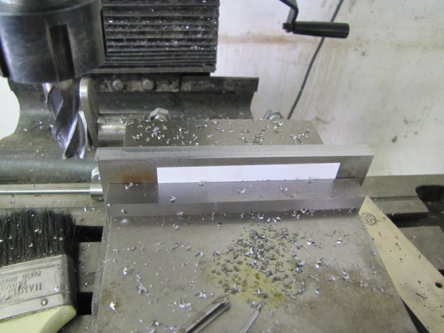
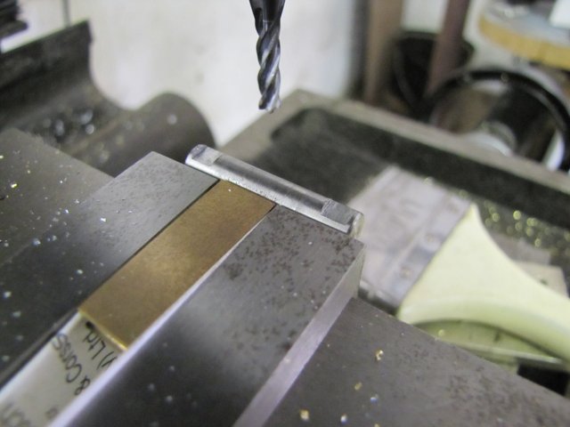
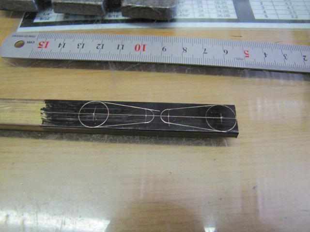
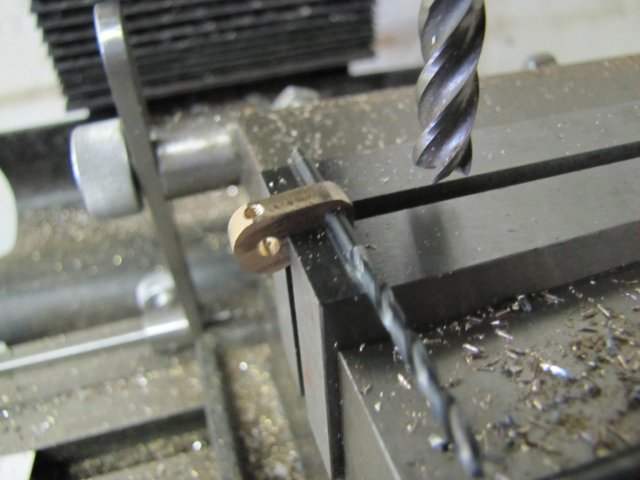
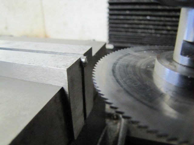
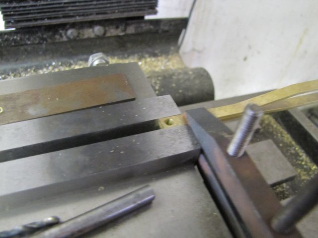
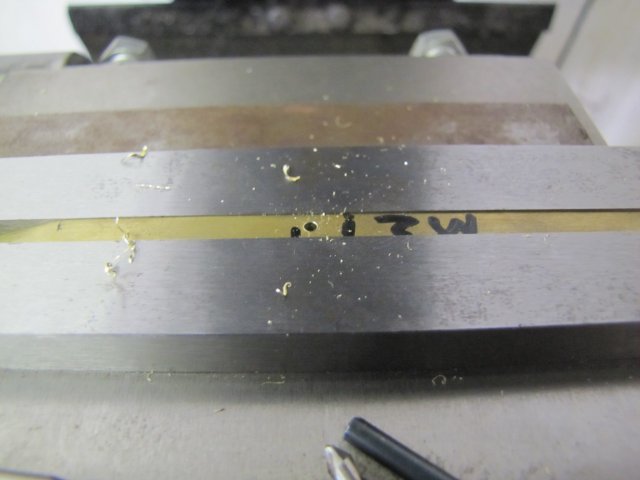
 . I have 1.2mm and 2mm. For a while I sat debating with myself whether to maybe make the rods from round rod, but decided against that as well. So, I'll use the 2mm plate, and I cut some strips from it:
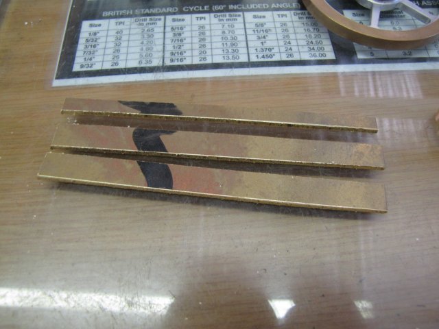
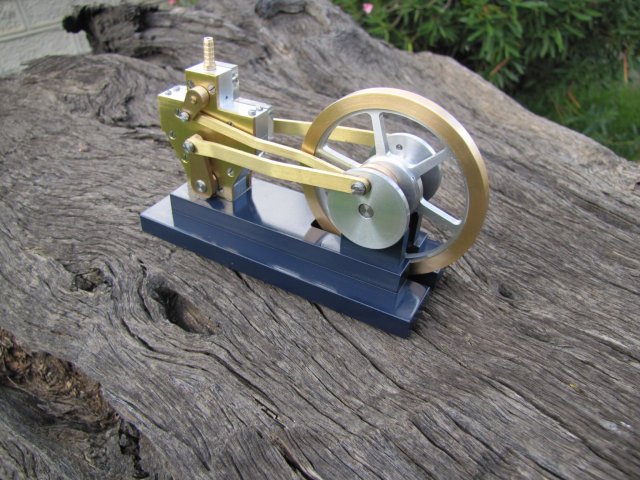
 This one's a bit slow - once it's done it'll join the others on the side-board in the lounge to trap unwary visitors :big::
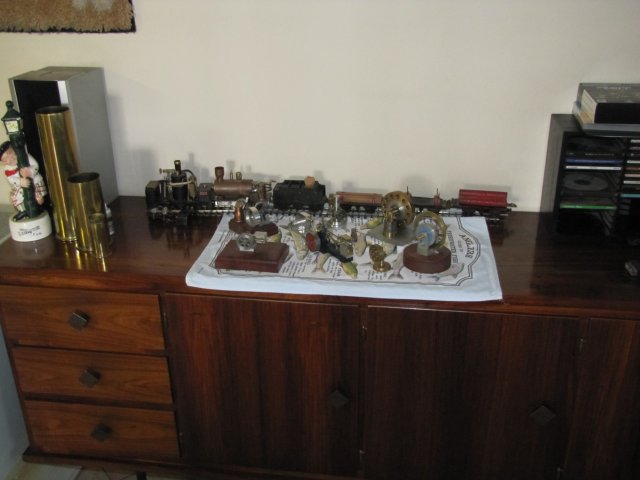
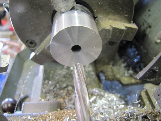
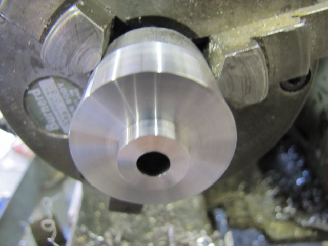
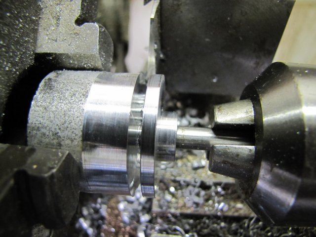
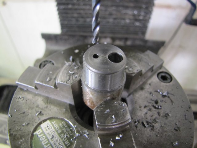
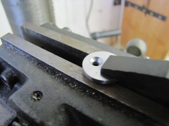
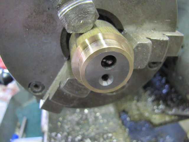
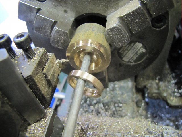
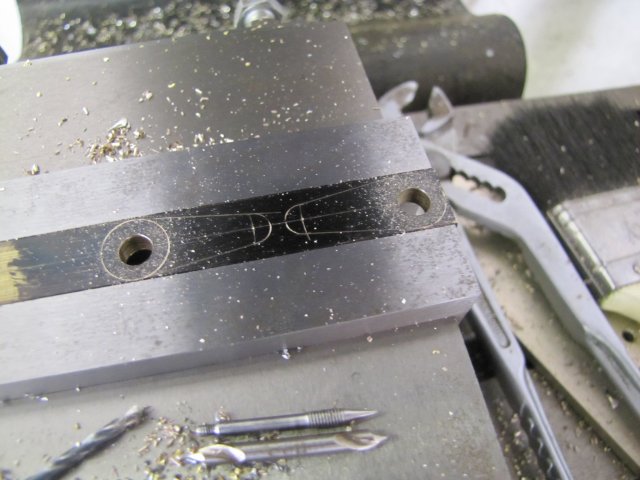
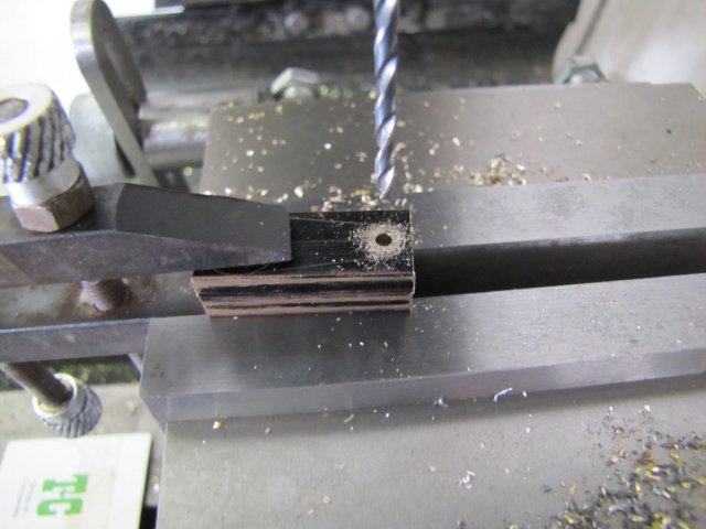
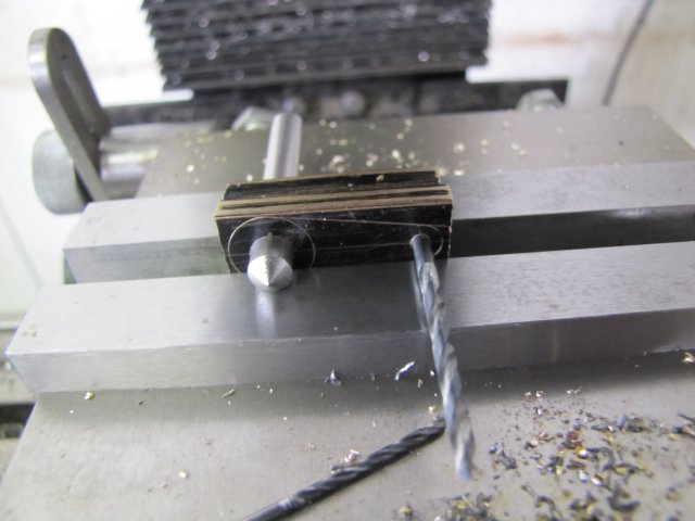
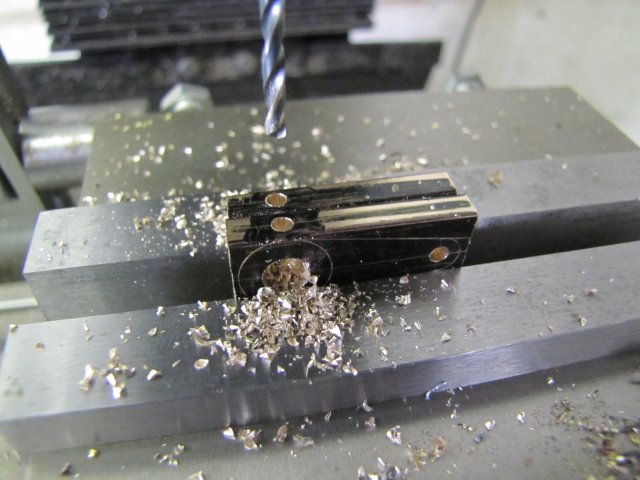
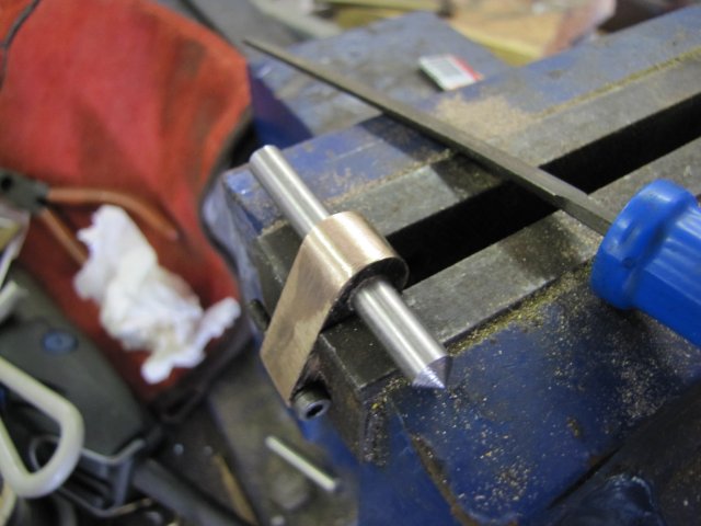
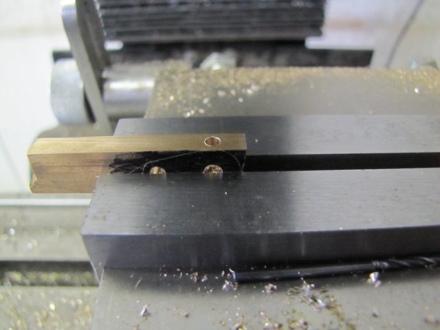
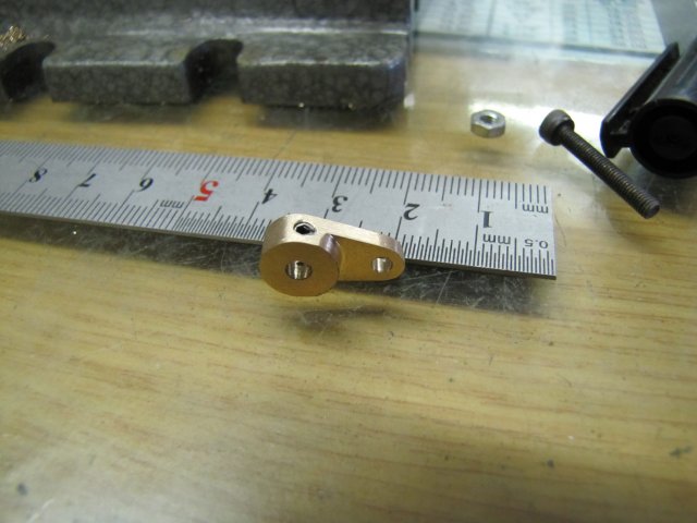
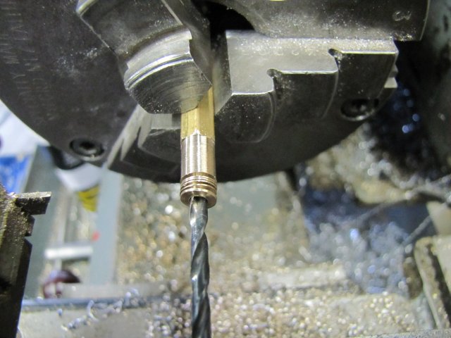
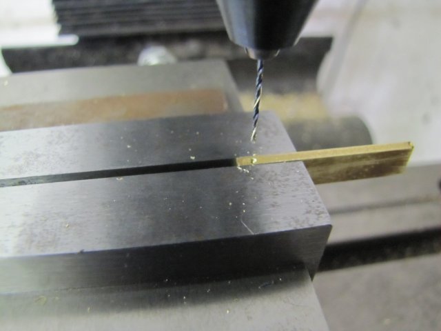
 . A quick spot with a center drill, and drilled a 2.5mm hole to thread M3 later:
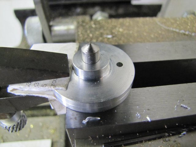
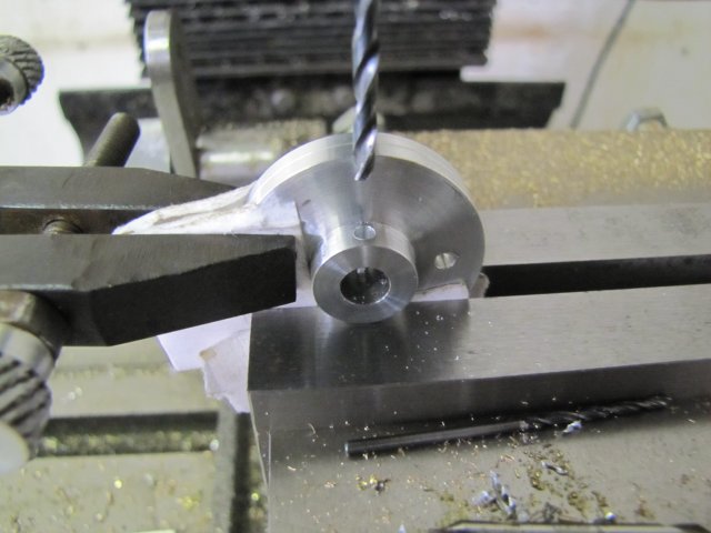
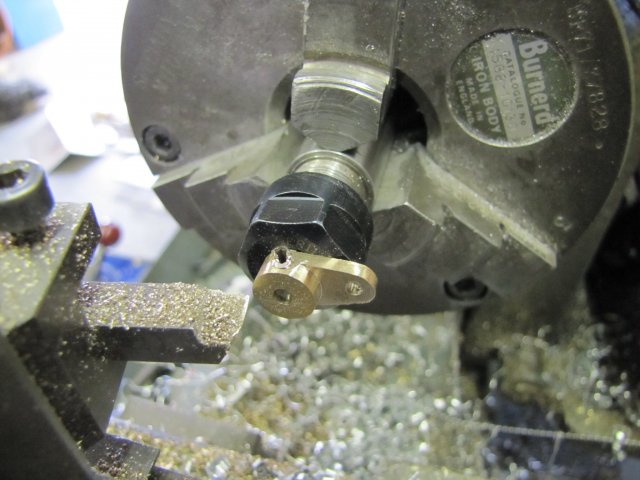
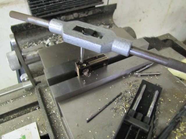
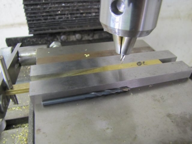
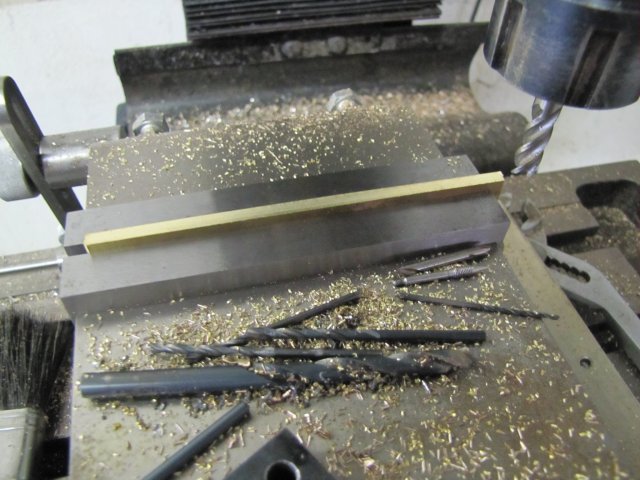 I guess I'd better start putting drill bits back in the index - before they slip into the fourth dimension.
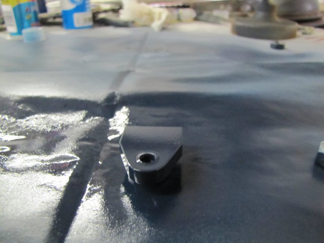 Thanks Dave - I tend to do some things a bit "old fashioned" :big: ; my face plate is a good bit of kit to use!; the "paperweights" I have in my office will also have to come home now, as I accepted that new job that will leave me office-less :big: - I'm getting to grips with the mill - though it still needs some sorting out; a power feed is definitely in the pipeline, but I must first get my small lathe installed properly as well. LOTS of tooling work to do once this engine is done ;D.
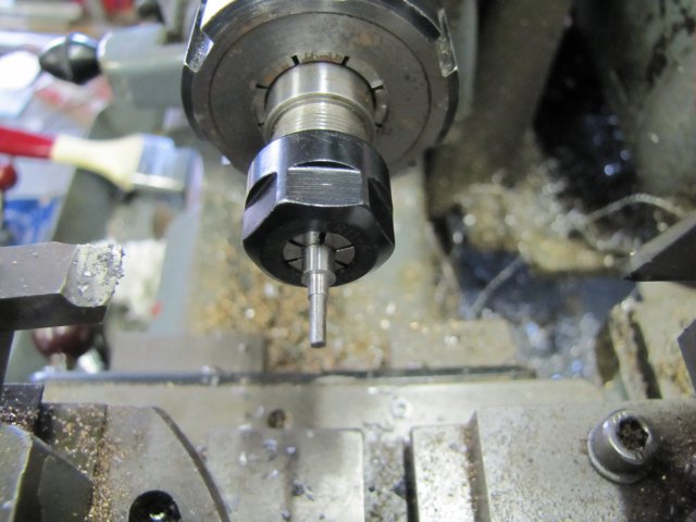
 :
:
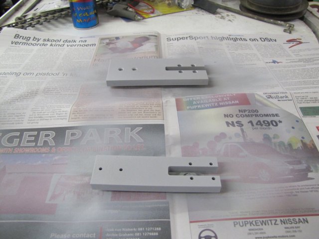
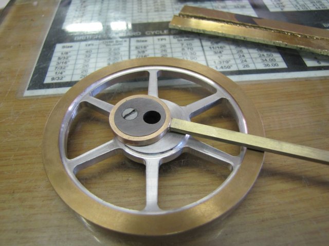
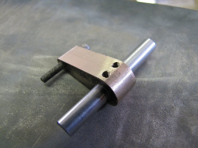
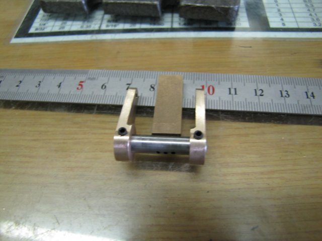
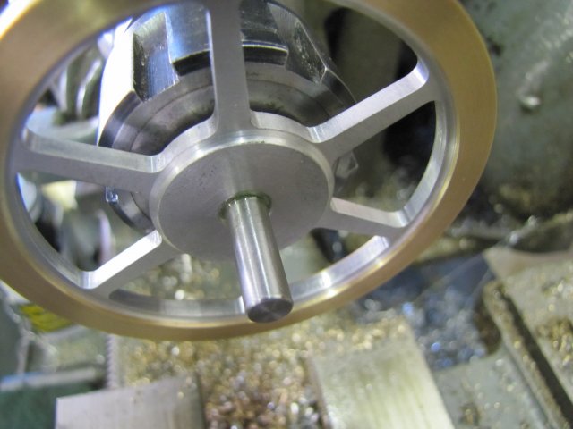
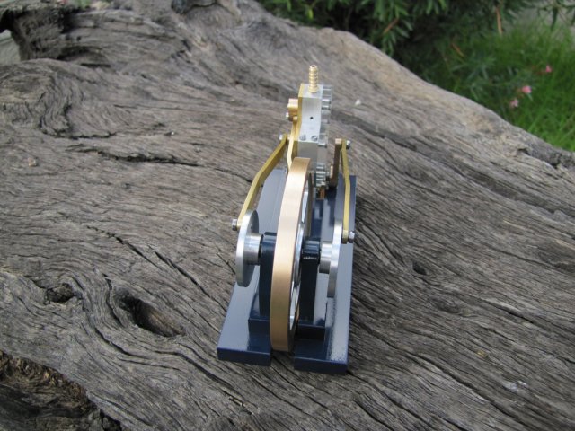
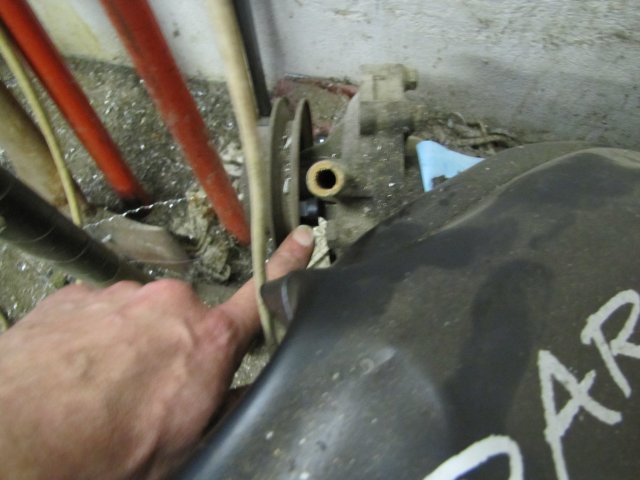 - that's exactly what HMEM is all about - ??? why do you wear pants with cuffs in the shop ? - that's a sure-fire place for swarf to collect and get you in trouble with the better half :big: - That's an old Ford Essex engine... No frame needed; just a long chain to make a boat anchor out of it; I just need the boat as well :big: - I had to assemble things well enough to judge how to bend the front connecting rod, as the perspex engine cover is quite a bit thicker than the cover from the plans:
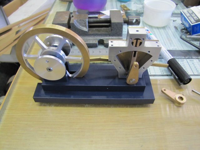
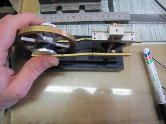
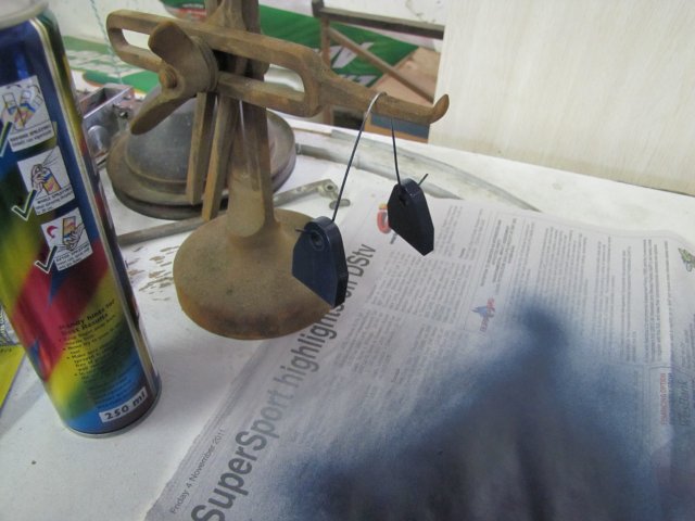
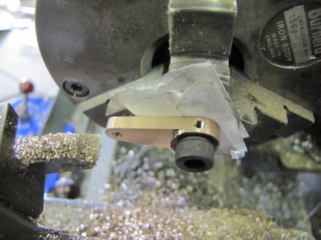
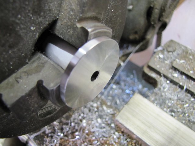
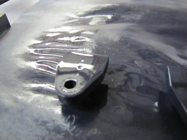
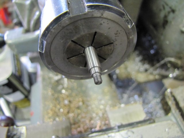
 Sorry - out of focus photo!
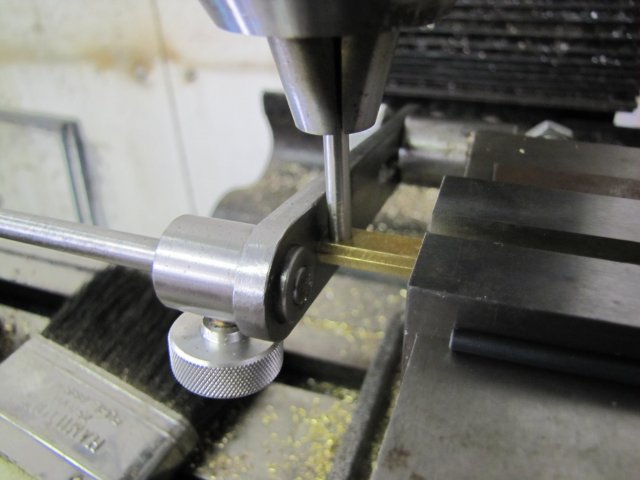
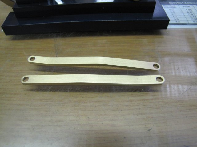
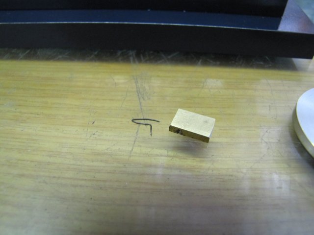
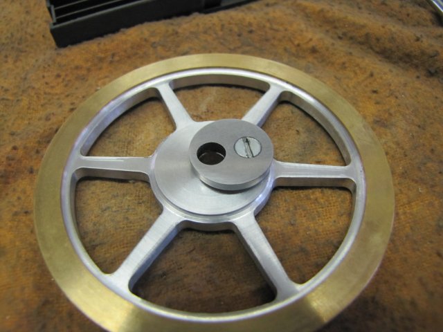
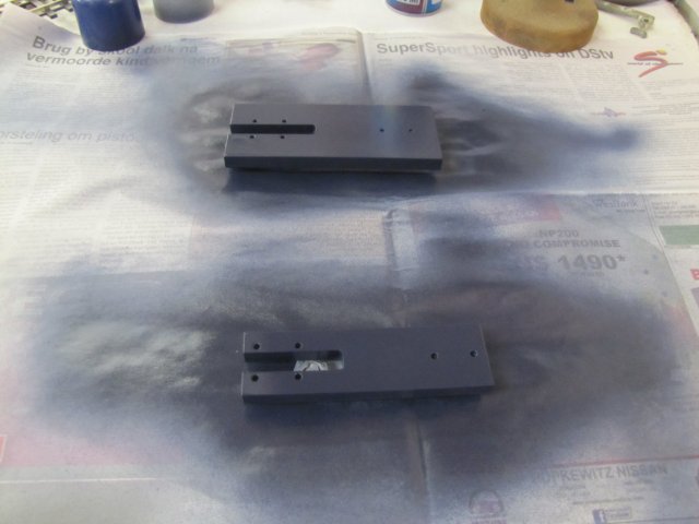
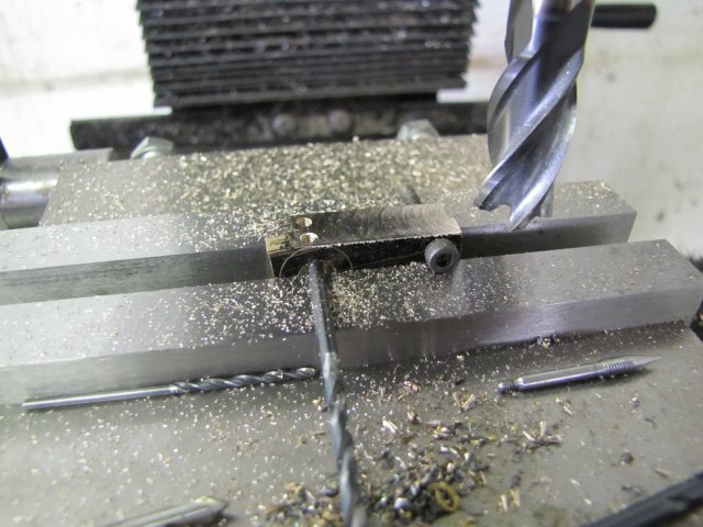
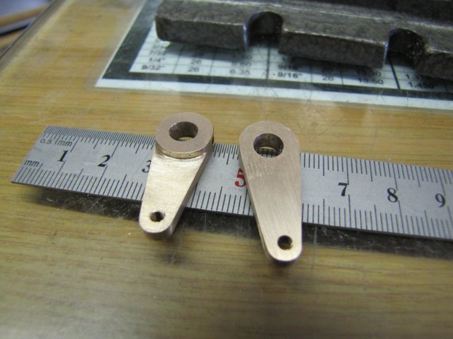
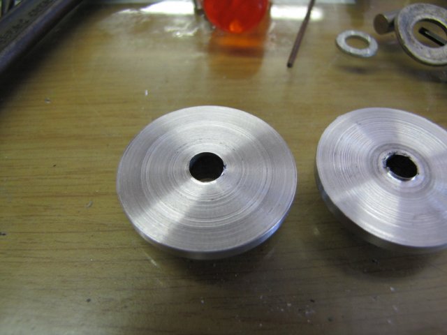
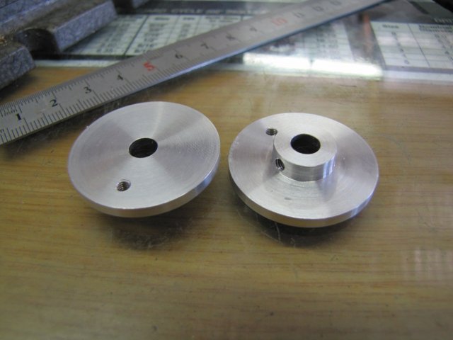
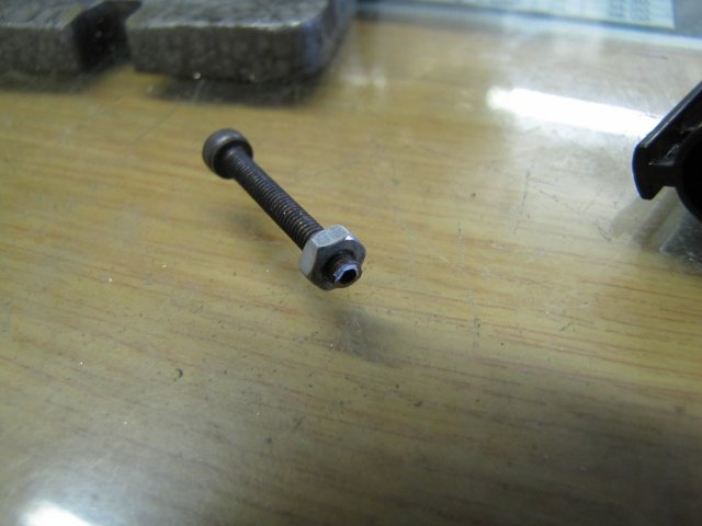
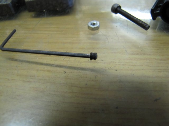
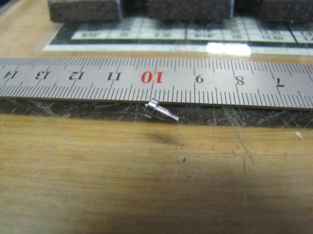
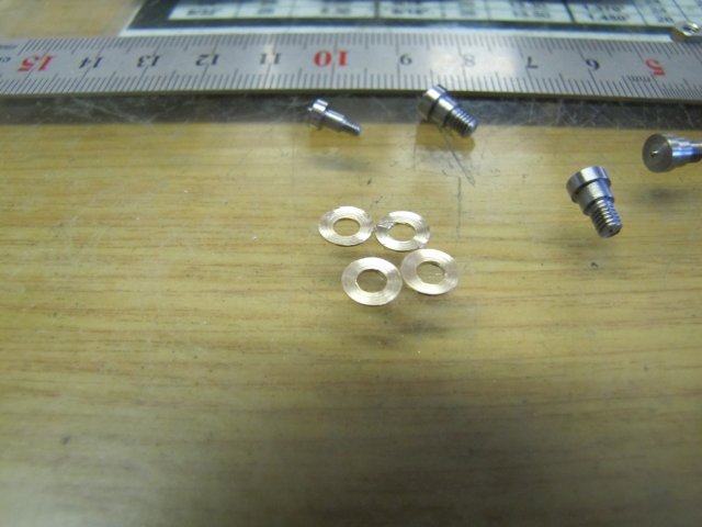
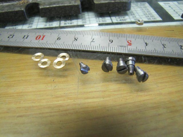
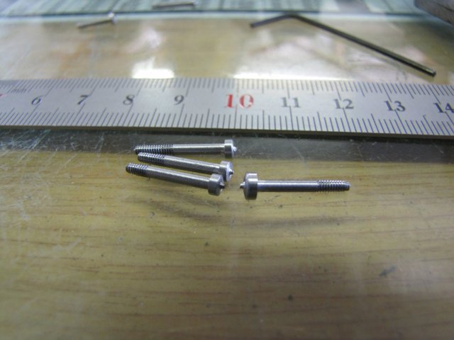 The one on the right's head is a bit big... I forgot to turn it down to 3mm :big:
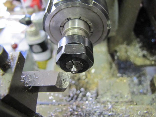

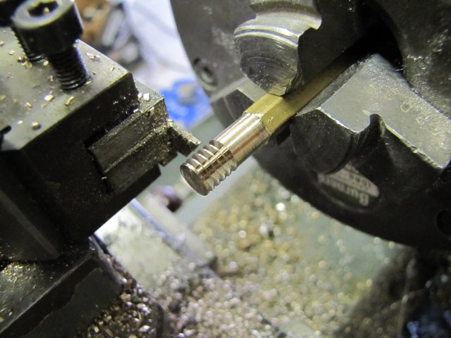
arnoldb said:Carl, thank you
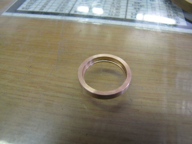
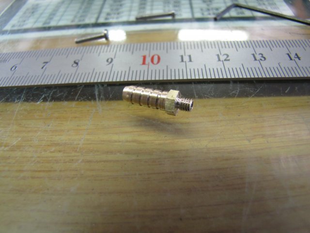
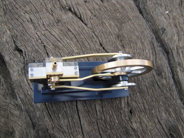
- Your wish is my command :big:. :-X That bottle is LONG gone - Doctor's prescriptions: Start the course and finish it :big:. I hope today's photos are OK! - a quick lick with a file and some emery cleared that up.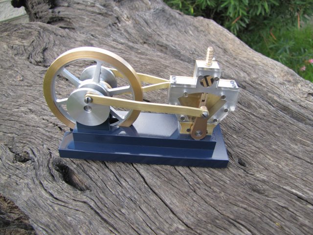
Enter your email address to join: