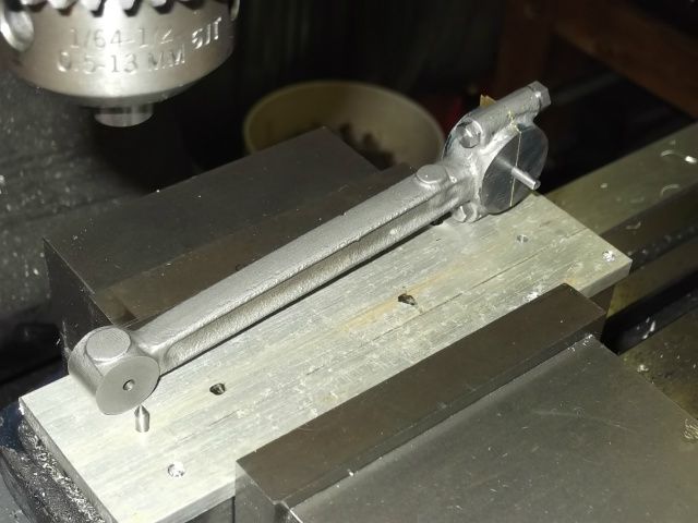
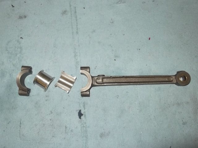
Fairbanks Morse

Home Model Engine Machinist Forum

Help Support Home Model Engine Machinist Forum:

This site may earn a commission from merchant affiliate links, including eBay, Amazon, and others.
That looks great Peter!

I agree that it looks monstrous if you compare it to the George made.

Cannot wait to see this one all painted and chugging away on a table in your workshop!

Andrew
 
I am just now catching up with this build Peter, and it looks great. Such nice work on that carb too!!! Will be following along more closely from now on.

Bill
 
Wonderful work on your carb Peter. Yes that think is a monster compared to most small carbs.
gbritnell
 
A little more this week;

As cast the piston was quite wobbly on the outside but the inside was true to the pin bosses.
I turned up a quick aluminum mandrel and pressed the piston onto it. This allowed me to turn the OD rough and the chucking piece concentric to it.
Reversed it in the chuck and cut off the mandrel. I was then able to bore out the mandrel stub and finish the inside of the piston. Then finished the OD to size, (1.4985") and ring grooves to depth at ring thickness +.005".
DSCF0098.jpg

DSCF0100.jpg

The drawings call out two piston rings but the full size used three, I am sure two rings are adequate but an extra groove won't hurt anything
DSCF0111.jpg

And it fits! ( no hammer required )
DSCF0116.jpg


Next step the milling machine for the pin hole.

Peter
 
Neat approach with the mandrel. I'll have to file that one away...
 
Brian;
I've used the mandrel idea a few times now, I just press it in tight and bore it out. Seems to get me started
ok.
Peter
 
A few more pictures of the Fairbanks progress. I've fallen behind on posting this week, my son is home from
the oil fields in western Canada, "the patch" they call it. So I have been living the adventurous life through his
descriptions.

Using a piece of flat stock inserted in between the piston pin bosses to set the future pin bore true to the mill.
I clamped the piston in the mill vise by the chucking piece and checked for square with a dial indicator in the spindle. Then machined a flat about 13mm wide on the chucking piece, this becomes the reference surface for the next setups.
I repositioned it in the vise with the flat to the fixed jaw, trued and centred the piston and drilled and reamed the 5/16 pin hole.
Repositioned to vertical this time and using a slotting drill opened the pin bosses to 14mm, then drilled and tapped one boss for a set screw to retain the piston pin.
Then chuck the piston in the lathe and part off the extra and face to length

DSCF0118.jpg


DSCF0126-1.jpg


DSCF0131.jpg


DSCF0137.jpg

Completed piston, I forgot to mention the oil hole in the top side of the piston, but that is just
another operation using the reference surface in the vise.
DSCF0149.jpg


Peter


Piston rings, I have been making some piston rings with reasonable results, also have bought a couple sets.
This kit came with a commercially made pair of 1 1/2" piston rings.
I fitted each ring by pushing it into the finished bore square using the piston, then measuring the gap with a feeler gauge.
Since my bore came out slightly undersize (.0005") the ring ends butted together I had to file the gap.

I have always used a file but decided to build a grinding jig to improve the squareness of the gapped ends.
Found a 3"x .0625 cutoff disc with exposed grit on the sides, other makes had the sides completely covered in resin.
The rest was put together with some very scratched 1/4"x 2" aluminum and a drill rod shaft
DSCF0156.jpg

By holding the ring square against the stops a couple turns of the crank CCW grinds the ring end to suit.
Cleaning and rechecking a few times resulted in a square ring ends and .004" gap.
DSCF0151.jpg

DSCF0152.jpg

DSCF0153.jpg


Peter
 
Great build so far and looking forward to the rest.
Love those little parts.

BTW, I can see a lot of those "grinders" being made! Brilliant idea and thanks for showing. One of those ideas like "now why didn't I think of that" Thm:

Kind regards,

Ron.
 
Thanks Ron, I can't take credit for the idea of the grinder .It's my miniature version of the real thing. These were used many years ago when each ring had to fitted to the bore it was going into.
I did see a performance engine being assembled in a machine shop a few years back using a modern version , with a diamond wheel.

Peter
 
Connecting rod,
I always seem to stumble when it comes to cast connecting rods and this was no exception.
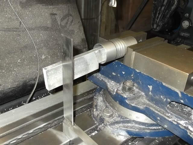
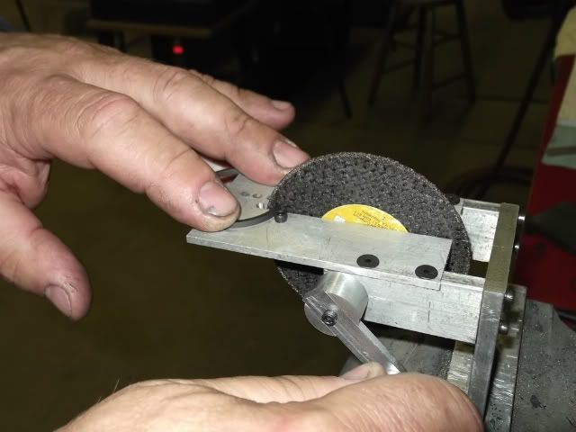
The sides of the beam portion were parallel so I started with the rod in the vise, I centred from the vise jaws
and milled the sides of the big end equal using the dro. I should have taken the small end to the same width
with this set up but that turned out to be hindsight.
DSCF0163.jpg


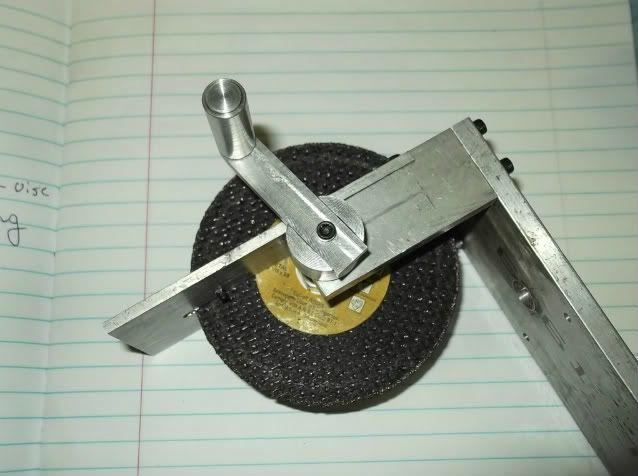
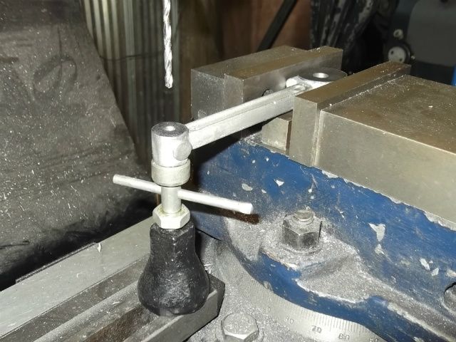
Using the milled surface, the layed (is layed a word?) out rod was set in the vise on a parallel (1/2" toolbit)
With a centre finder I swiveled the vise until both centre marks were even on the X axis. Then working from the rod eye as zero drilled a 1/8" hole at each centre
DSCF0165.jpg


With pins in the centre holes the casting was set up square on an angle plate to drill and spotface the
bolt holes. After this the cap was sawn from the big end, and the rod remounted square on the angle plate.
The mating surface was milled down to 1/2 of the centre hole diameter.
DSCF0170.jpg


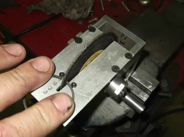
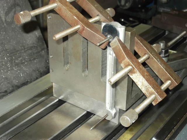
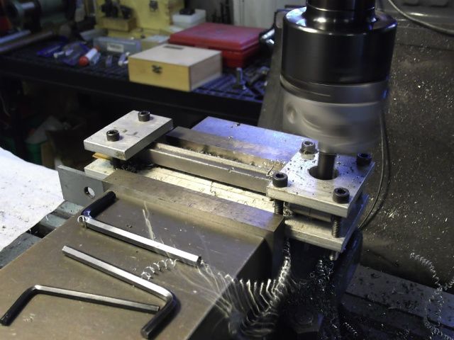
I set up a plate in the mill vise centred, located, and drilled the 1/8" centres and threaded holes for clamping down the part.This plate was zeroed with the dro and not removed till finished.
The connecting rod cap which was set up using the spot faces and milled to thickness after being cut off, was bolted back in place. Following real world practice I assembled it using shims (3X.002") for bearing adjustment..
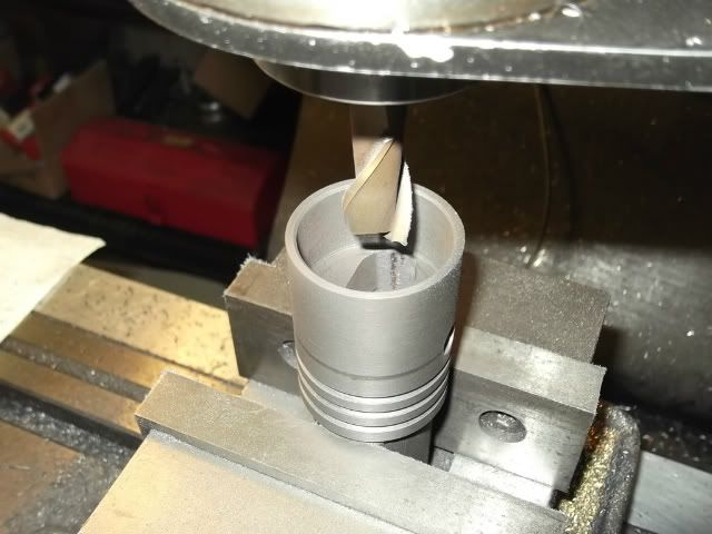
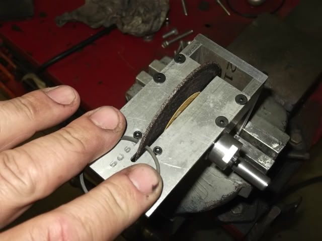
With an end of one locating pin filed to half the diameter to suit the half hole at the big end, the rod was located and clamped on the jig plate as pictured.
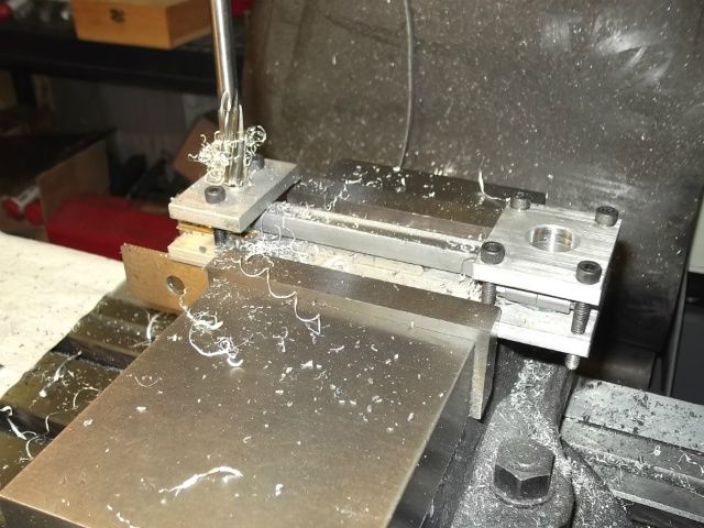
I had to shim the small end because of not making the thickness equal to the other end. I used a dial indicator on the surface of the rod and shimmed until it read zero deflection when clamped.
DSCF0174.jpg


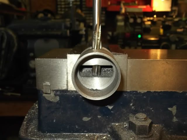
Drilled, bored and reamed to size.
DSCF0179.jpg

DSCF0186.jpg


After the holes were finished the assembly was removed and reset in the vise to drill oil and grease passages,
using the jig plate to locate the drillings.
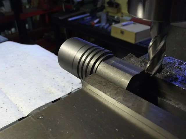
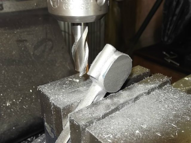
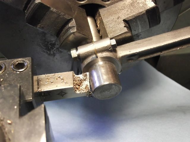
After removing from the plate the rod was clamped on a mandrel in the lathe and the big end turned to width
DSCF0190.jpg


Hope this makes some sense, even writing it seemed clumsy
Peter
 
Peter

You are a life saver. I have come to the stage of working on the conrod casting for my engine and I picked a couple of tricks from your explanation. Unfortunately my casting is not as good as yours but you still helped.

Vince
 
Peter

Forgive my inexperience but when you said :

Following real world practice I assembled it using shims (3X.002") for bearing adjustment

Why does one do that?

Vince
 
Love the action boring shot!!! ;D

Have you moved the mill Peter??
Does not look like it is against the wall anymore.
Sneaking more tooling into the workshop?? :big:

Andrew

PS- Thank you so much for the full set of drill bits!!!
Used one the other day and it cut like butter!!!!
 
Following real world practice I assembled it using shims (3X.002") for bearing adjustment

Why does one do that?

Vince

Hi Vince;
It was common practice with poured and inserted babbit bearings to have shims between the cap and
connecting rod. Because lubrication was marginal at best a lot of bearing wear was experienced, also
many engines have the shims extending in between the bearing halves to stop them from rotating.
My reasoning is originality and functionality, I am using aluminum bearings and plan on this engine
doing some work because it is throttle governed. I do expect some break in wear to occur.

Peter
 
Hi Andrew;
Nope I haven't moved the mill, it's too big or I'm too lazy so it will stay where it is.
No new tools lately
Your welcome for the bits, use them in good health.
Did you go to Names?

Peter
 
Hi Peter,

I just thought the mill looked like it was moved...
Don't remember the bench behind it.

I did not go to NAMES....
Hopefully we can go to Cabin Fever next year??
Did you make it out to NAMES this year?
We had to do stuff with the kids this weekend.

Andrew
 
Con. rod continued,
After completing the con. rod I made the bearing halves using 6061 aluminum. Made two complete bearings
and cut each one a little more than half. Each was set in it's seat and filed to the height of the rod/cap.
Some controversy about aluminum bearings on HMEM in the past but has worked well for me, and has the look of a Babbitt bearing.
The drawings called for a .250" piston pin, I enlarged to .3125" and it looks like I could have gone even larger
DSCF0192.jpg


The connecting rod installed in the engine
DSCF0199.jpg


DSCF0200.jpg


Peter

Assembled and soon ready to test run!
DSCF0207.jpg
 
Wow!!!!
That looks amazing Peter!!!! :bow:

Can't wait to see and hear it running!

Andrew
 
It's running!
Not well yet, but I'm working the bugs out, first run it was firing on maybe every third compression.
Tried some carb adjustments on the air valve but little help.
The spark plug hole is very deep and opens into a recess above the intake valve, so I thought a longer
reach spark plug might be the answer. this is my first time for making a plug, I looked around on here and found George Britnell's tutorial and followed his excellent instructions.
The bottom spark plug is a 1/4" 32 long reach Rimfire
DSCF0214-1.jpg


Since this is a pratice piece I tried making it with a fixed gap, kind of a modification of a surface gap plug. I made the bottom of the plug body.030" larger in diameter then the electrode. the centre electrode extends from the insulator flush with the body leaving a gap of.015" around it. Tested and running with a full size T type buzz coil, it works. Lights up bright blue and no visible leakage, I did not grab it to find out more.
DSCF0219-1.jpg


This helped the running slightly, I also found an intermittent problem with the ground contactor for the ignition.
Finally runs well enough that the governor acts to close the throttle. Before I got things smoothed out any more the governor spring adjusting sleeve unscrewed itself, meaning complete disassembly to correct. Getting closer.

Peter
 

Latest posts

Back
Top