Engine from Jan. 1953 Popular Science.

Home Model Engine Machinist Forum

Help Support Home Model Engine Machinist Forum:

This site may earn a commission from merchant affiliate links, including eBay, Amazon, and others.
The exhaust ports seem strange. Being in the center of the cylinder that means the exhaust occurs at one half the stroke- you loose the expansion of the last half stroke. Does this make it a Uniflow engine? What will you do to connect the exhaust ports? There doesnt seem to be a drawing of that side of the engine.

Very nice work on the engine,

It is a Una-flow engine. I don't plan on doing anything for the exhaust side. Maybe in the future I might, but I like the way it sounded in the video and doing something might affect that.

We shall see.

Gary
 
I know I said the connecting rods are next, but I figured that I would knock these out real quick.

These are the valve sleeves which are located in the block at each end of the cylinder block.

I wanted to make them removable so I hold them in place with a set screw. (I screwed up and drilled holes in the input port side first so you see two sets of holes)

I cut a groove in the center of the sleeve so that any gouges the set screw made would be under flush so I would have no problem removing them.


PS-047_zps003d6706.jpg


Then with them screwed in place I used the existing holes to drill into the sleeve.

PS-049_zps4b6b5a9d.jpg


PS-050_zps7255fa90.jpg


Here is an out of order picture with no holes in the sleeve yet but it shows the sleeve in place.

PS-048_zpsd2dfde16.jpg


Now on to the connecting rods.

Gary
 
Now the connecting rods as promised. They are a lot of work and setups.
I am going to do these in two posts.

First I start with some .750" brass stock.

PS-051_zpscd858d18.jpg


Then I turned the columns or shafts of the rods.

PS-052_zps85dbe8e1.jpg


Then flattened the opposing sides.

PS-054_zpsb491d23d.jpg


Here they are with the small top end to the proper size. The crank end still needs to be brought to size.

PS-055_zps883f4197.jpg


Now I'm machining the other surface to size. You will notice I used a gauge pin under the end of the part as a spacer.

PS-056_zpsc468db05.jpg


And here they are with both ends brought to size.

PS-057_zps83b75911.jpg


And here they are with the crank end cut off on the bandsaw, machined and tapped for screws.

PS-058_zpsa3e0cde4.jpg


Then I drilled and reamed the holes in both ends. Notice the gauge pin again.

PS-059_zps04c149b6.jpg


And here they are complete to this point.

PS-060_zps6c8f1824.jpg


I'll finish them up next time.

Gary
 
Now for the conclusion of the connecting rods.

First I needed to make a fixture to turn the cheeks (for lack of a better term) of the crank end.

PS-061_zpsc830f84f.jpg


Then I mounted and turned them.

PS-062_zpse8dba531.jpg


And they end up looking like this:

PS-063_zps9f2b72e9.jpg


Then on to the slot. I used a .187" thick blade in the center to start. then moved it up and down to create a .250" gap.

PS-064_zpsaca38b3d.jpg


Then rounded the base of the cut by plunging a 250" endmill.

PS-065_zpsb9681db7.jpg


Almost done, just another trip to the rotary table to round off the ends.

PS-066_zps440dfcc4.jpg


And they end up looking like this. Complete. Just need cleaning up.

PS-067_zps1eed6331.jpg


Not sure what I'll start with next so we will have to wait and see.

Gary
 
Now for a couple of pretty simple parts.

The crosshead and slider for it.

Not really that much to say about them. Pretty straight forward.

The slider just has straight holes until I figure out what kind of fasteners I want to use.

Gary

PS-90.jpg


PS-91.jpg


PS-92.jpg


PS-93.jpg


PS-94.jpg
 
I was looking for a suitable direction on turning con rods, and I have found it in your post. Thank you for taking. Your time to post these and your work. One ? Though. When milling your square ends are the over sides to provide the curved outer edge, and sized, or are they marked out beforehand amd milled to size.

It will follow others saying your work is superb , I hope my similar engine can carry some of the status yours does/will. I look forward to your thread as I'm sure many others do too.

Mike
 
It's coming on at a fair old speed.

I have a question about the pistons. In a uniflow engine, as far as I have seen, the pistons are normally unusually long, equal to the stroke less the exhaust port width. It is hard to tell from the drawings, but it looks as though the pistons on this engine are more like the conventional thickness. Could you tell me what are the stroke, the effective length of the cylinder (less cover spigots), piston thickness, and exhaust port width (diameter), please?
 
When milling your square ends are the over sides to provide the curved outer edge, and sized, or are they marked out beforehand amd milled to size.
Mike

Sorry, but I don't understand your question?

Could you tell me what are the stroke, the effective length of the cylinder (less cover spigots), piston thickness, and exhaust port width (diameter), please?

The cylinder length is 1 3/16". The stroke is 7/8", the pistons are 1/4" thick and 1" diameter. The exhaust port is 3 holes .136" in diameter per cylinder.

Gary
 
Now for the crosshead / reversing gear mounting thing. I don't know the proper name.

First I squared up a blank.

PS-095_zps7c3d8602.jpg


Then while it was still square I drilled the holes for the reversing gear shaft. I found the edges on both ends before I drilled the holes. I didn't want the hole to wander, plus I didn't have a drill bit long enough even if I wanted to. :)

PS-096_zpsd86be158.jpg


Then using some spacers to save my bit and vise jaws I did some shaping.

PS-097_zps3038e9c8.jpg


Then I bring it to the proper thickness where needed.

PS-098_zps9cb39742.jpg


Then using a 90° countersink I chamfer the edges.

PS-099_zpsec108776.jpg


Then reposition it to profile the other edge.

PS-100_zps533af56d.jpg


And here it is before any more holes.

PS-101_zps8724cf8e.jpg


Then the next two pics are the completed part.

PS-102_zps76925fb2.jpg


PS-103_zpsccf06476.jpg


I just picked a thick part for the set screws.

Next time I will probably be starting the eccentric straps. They look pretty involved.

I thought the same thing about this part when I first looked at it, but it was actually a very simple and fast part to make once I figured out a plan of attack.

Gary
 
I like your setups, and the parts are very nice looking machined parts,
this is a very enjoyable progress to watch, lots of pictures makes for it really enjoyable to follow.
Thanks for sharing this with us.
 
Sorry for that. I was trying to see If you turned your outer radius before or after milling the flats. I think it makes sense now looking thru your post again, are you turning first to size then mill the flats The problem I am having is making sure when milling flats that they are parallel with the centerline, not sure how to lay it out starting from round.
 
Sorry for that. I was trying to see If you turned your outer radius before or after milling the flats. I think it makes sense now looking thru your post again, are you turning first to size then mill the flats The problem I am having is making sure when milling flats that they are parallel with the centerline, not sure how to lay it out starting from round.

For starting from round the second cut is the important one. Make sure it is equal to the first.

For example starting with a 1" bar. Make a cut along the length. Say you cut off .100".

Rotate your bar to rest on the flat and clamp it. Then just lower your cutter .100". You should end up with two surfaces parallel to you center line.


In my case both my square ends were different dimensions. That's why you see me using a gauge pin to make up the difference when I clamped it.

Make sure you have a wide enough parallel to set your round stock on.

Hope this helps.

Gary
 
I've been wondering how people are doing this! But how are you guiding it around the corners? Just by hand or is this CNC?

Also the setup is pretty genius. I would have done some dumb two-part thing by holding it vertical and then laying it down to put the radii in the corners.
 
Now for the eccentric straps. Since I am adding a reverse to this engine I will need 4 of them.

First thing I had to do was to make up some stock from a 3" diameter solid bar and save as much material as I can. I ended up with these funny shapes.

I printed out patterns full size to make sure I didn't cut into the parts when roughing them out.


PS-105_zps16ff8ba8.jpg


Then I used the center line of the pattern against the top of my vise to cut the sides flat. This gave me enough of a flat to square both ends. It's not really critical as long as I have room to spare.

PS-107_zps953ac1fa.jpg


Then I squared a corner on the smaller parts and then drilled and tapped holes for temporary screws.

PS-108_zps300fa2ad.jpg


I marked the parts with small dimples in the mating surfaces to keep the pairs together.

Next I cut them to final width. Then I drilled holes smaller than the final size in both ends.

PS-109_zpsbee44639.jpg


Then I cut the taper on both edges. I calculated the sizes of the two gauge pins to give me the correct taper.

PS-110_zps97d5f04a.jpg


And here they are completed to this point.

PS-111_zps90f77907.jpg


I will continue in the next post.

Gary


Also:

I've been wondering how people are doing this! But how are you guiding it around the corners? Just by hand or is this CNC?

Also the setup is pretty genius. I would have done some dumb two-part thing by holding it vertical and then laying it down to put the radii in the corners.

It's all done by hand. I just figured out in advance where to stop and start the cuts.
 
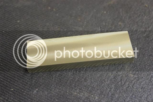
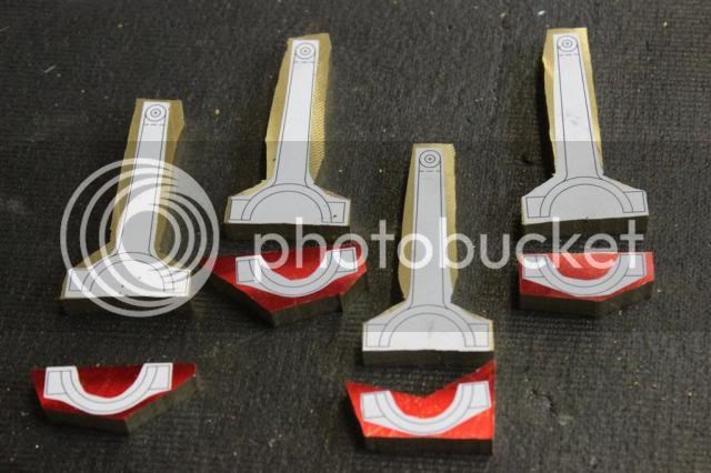
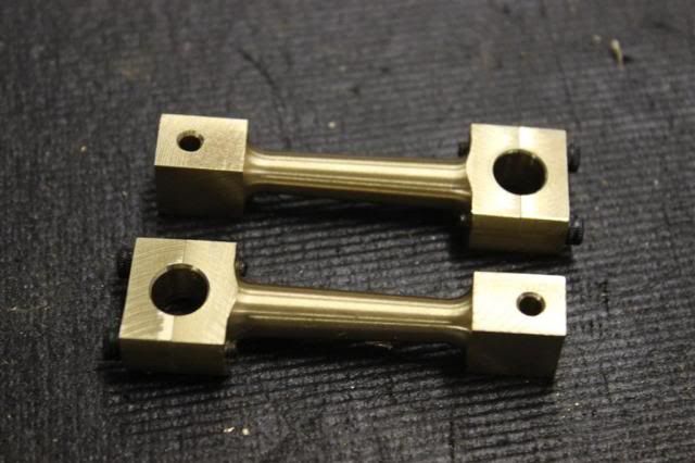
This post will show the completion of the eccentric straps.

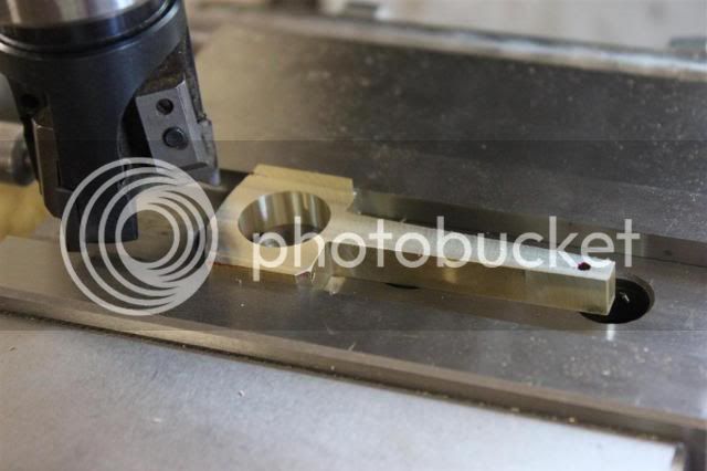
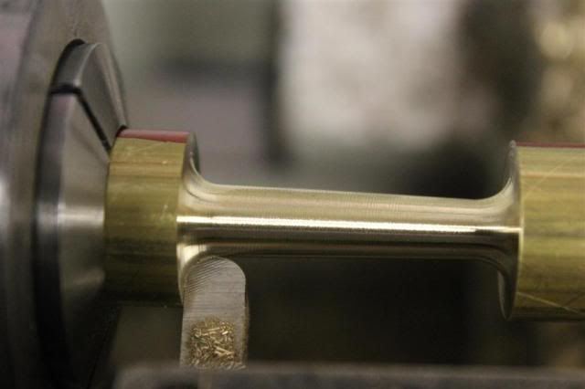
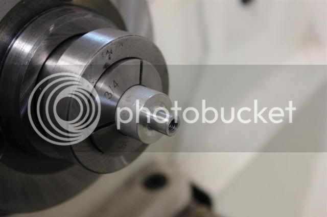
I start by boring the large end to final size.

PS-112_zps79d446d5.jpg


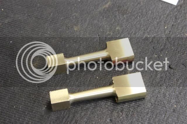
Then I thin the part to the largest thickness, which is the small end.

PS-113_zpse260bced.jpg


Then bring the large end to final thickness.

PS-114_zps0c6f09c7.jpg


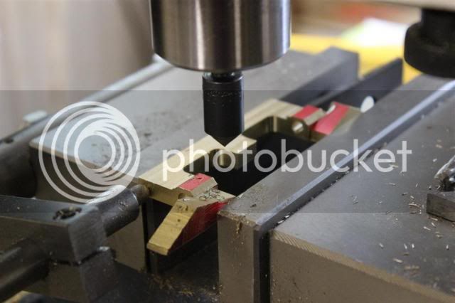
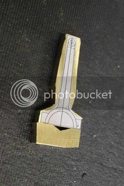
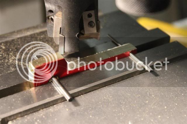
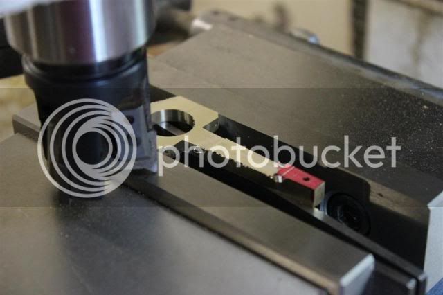
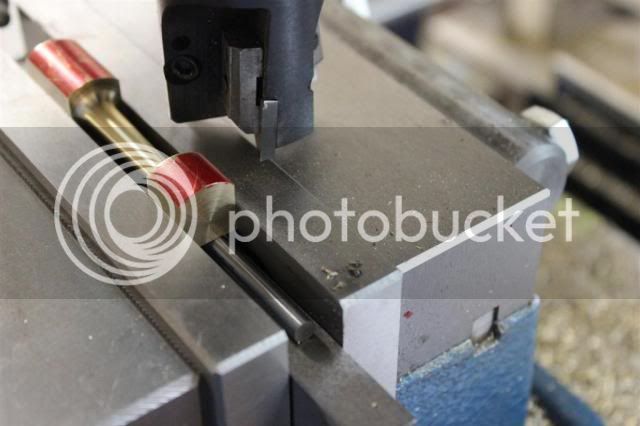
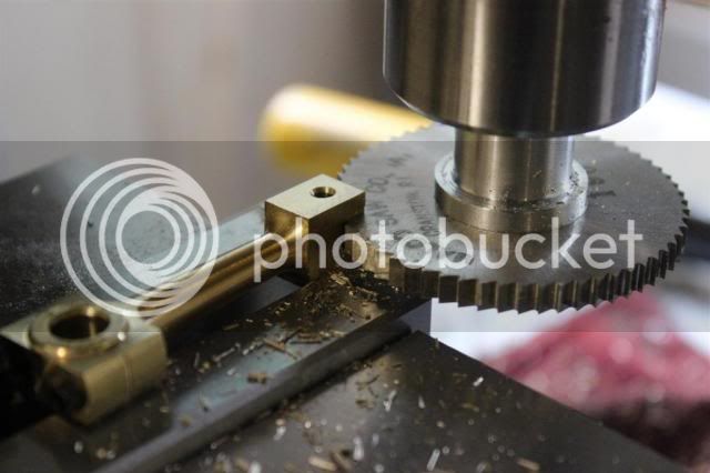
Then using a .125" saw I cut the slot.

PS-115_zps8928b155.jpg


Then on to the rotary table to shape the upper part of the large end and bring the strap to final thickness.

PS-116_zps89226249.jpg


Then using a ball endmill I radius the transition.

PS-117_zps78790864.jpg


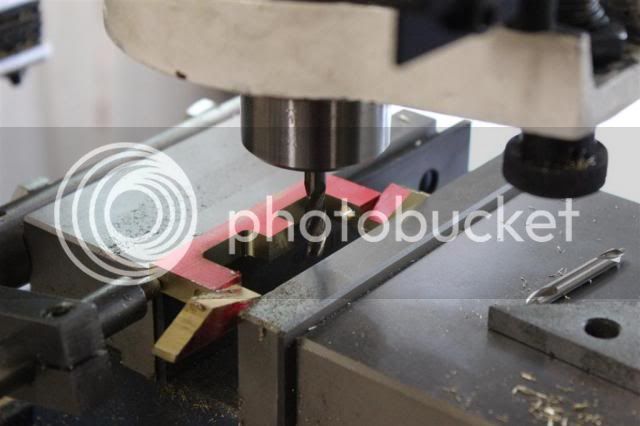
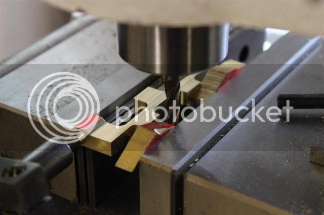
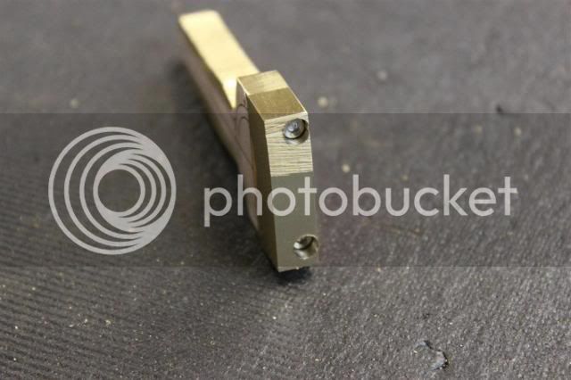
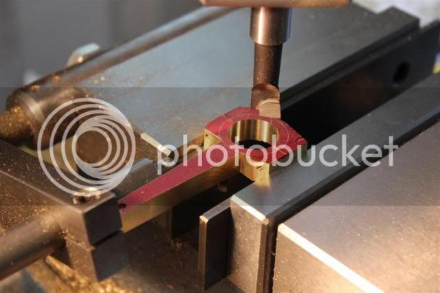
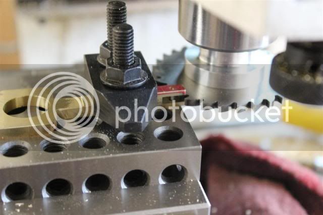
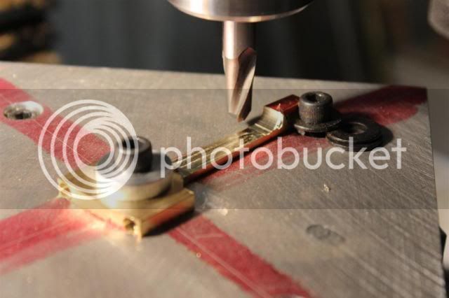
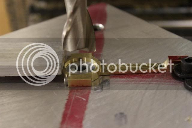
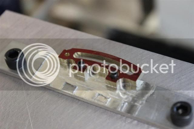
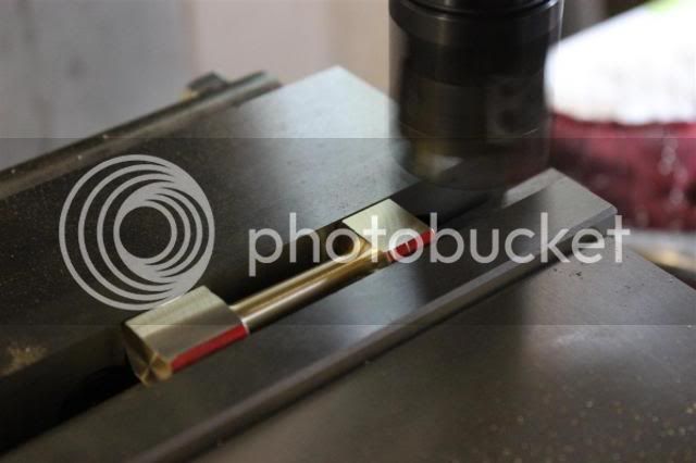
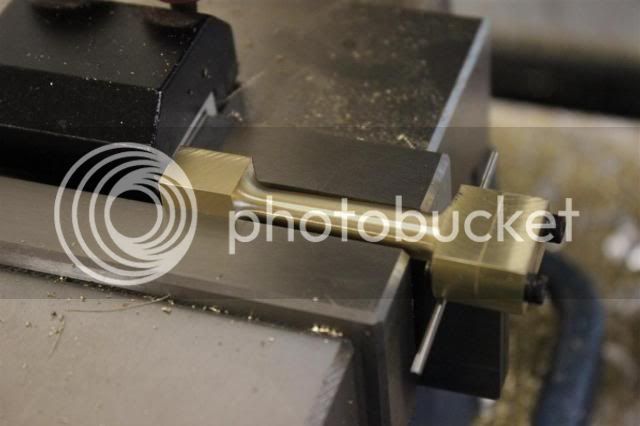
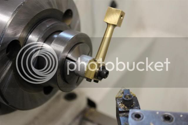
Now the worrisome part. I want to cut the profile on the lower half but I am concerned about the part jumping out the the fixture since I will be making a climb cut. What I did was to add a .002" shim under the clamp to make sure it was clamped securely and approached the cut from a direction to minimize the chance of the part coming loose.

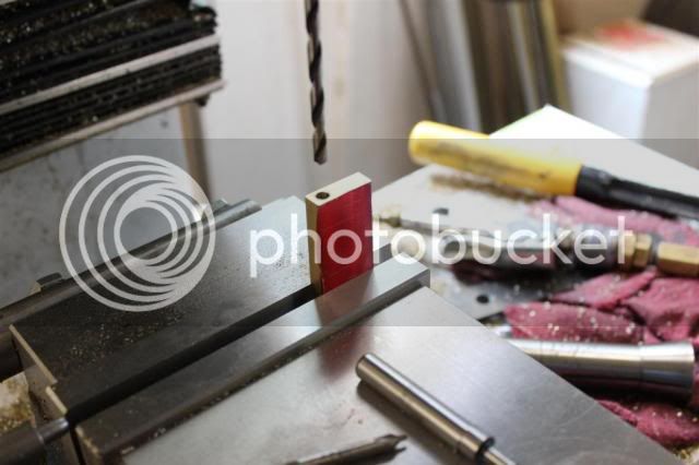
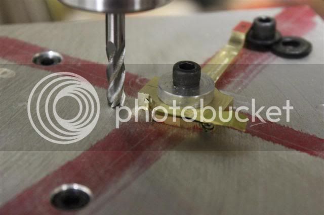
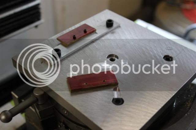
I left the screw in the other end.

PS-118_zps914978bd.jpg


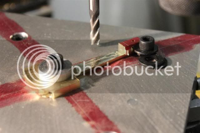
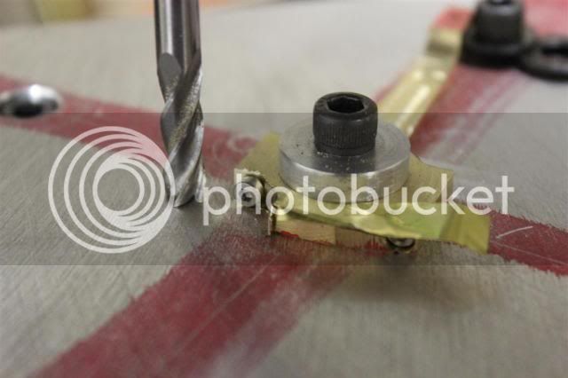
Then I replaced the screw and removed the screw from the other end.

PS-119_zps80a560cf.jpg


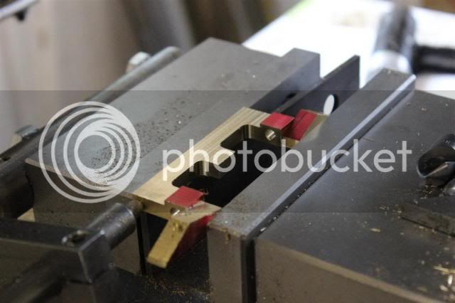
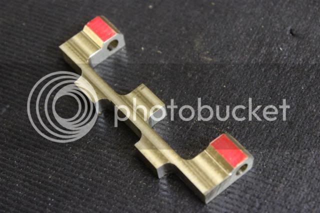
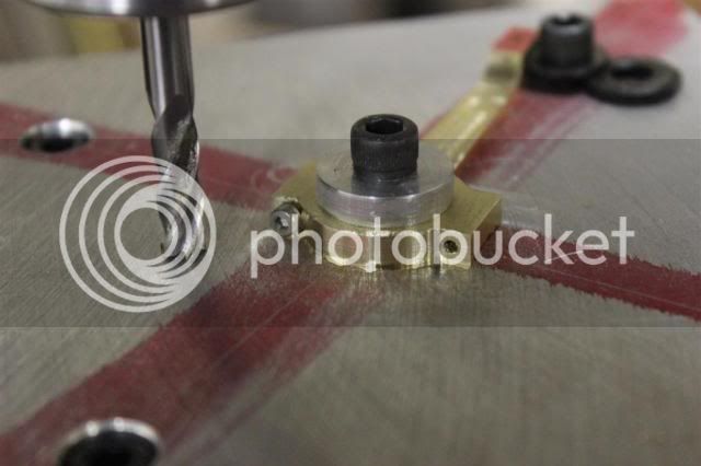
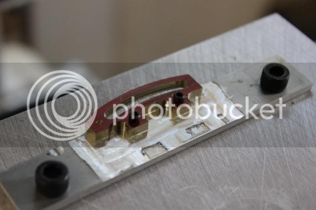
Then just made the cut in the normal way since I wasn't worried about the part coming loose cutting from this direction. There is a very small amount of material left at the bottom edge because I left the mill .002" above the table so as not to cut into it.

PS-120_zpsec30fdf5.jpg


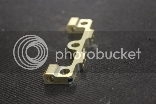
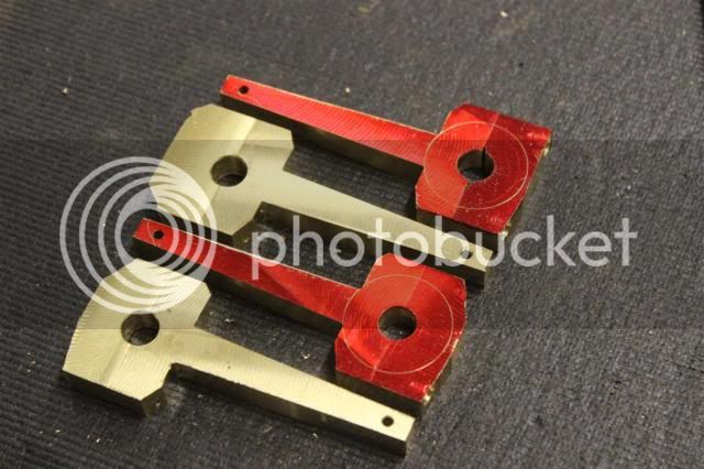
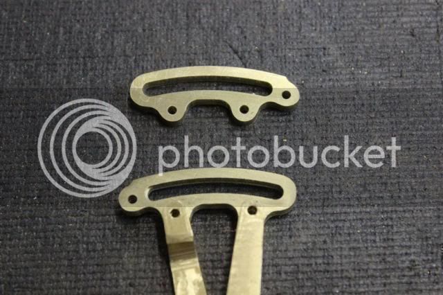
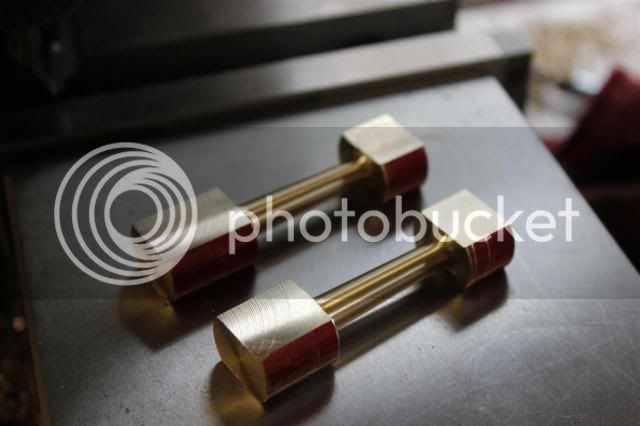
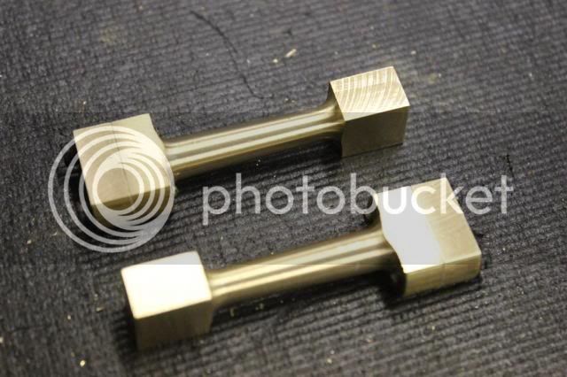
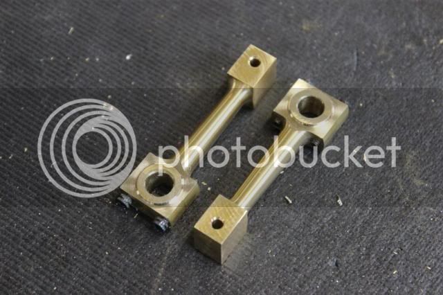
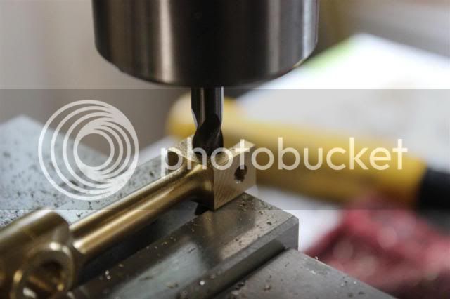
Then I used a endmill to create a counter bore on both sides to leave a "rib" in the middle. It looks like the usual way to make this is to cut a groove instead of a rib, but I figured it would be easier to cut the groove in the eccentric.

PS-121_zps218e6a66.jpg


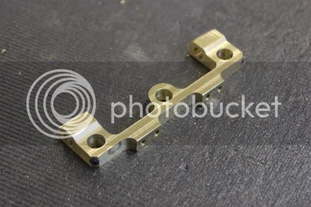
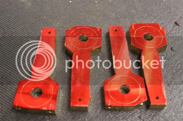
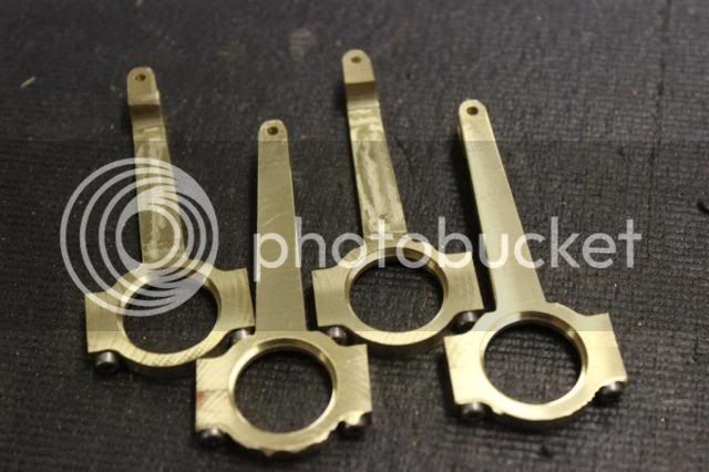
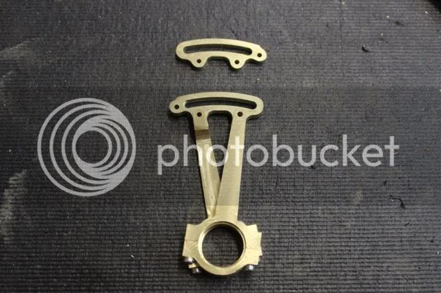
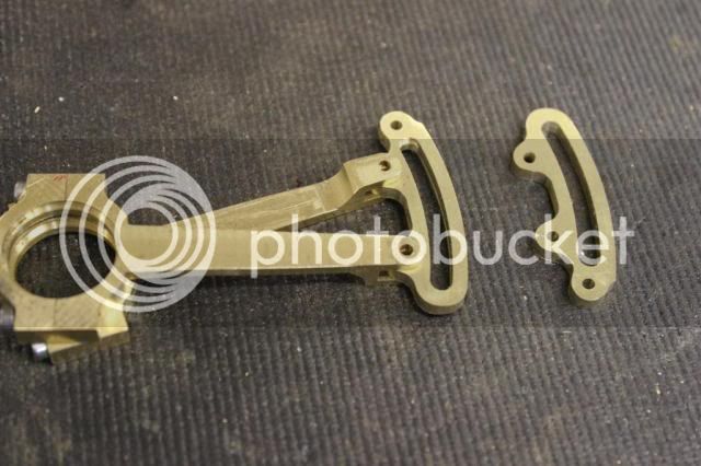
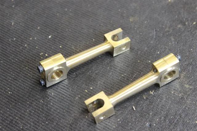
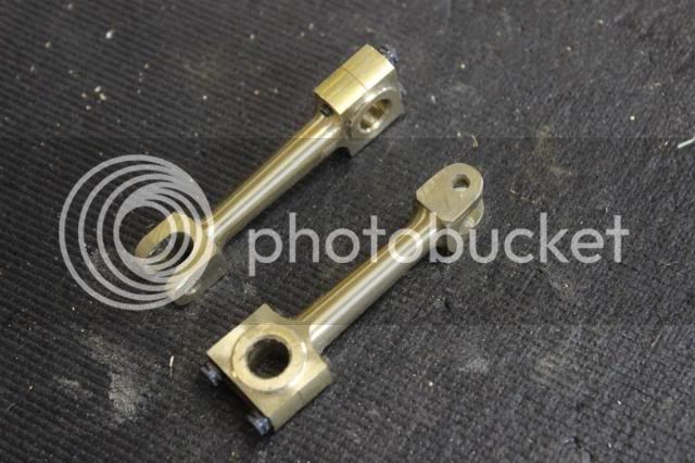
Then lastly, here they are all done.

PS-122_zpsc35ba4ae.jpg


Not sure what part I will make next, but I will be running out of things to make pretty soon!

Gary
 
Now for the expansion link (I assume that's what's it's called)

First I make a fixture to hold the part at the correct radius.

PS-123_zps1fedf347.jpg


Except for the cuts for the slot and the top edge, all the cuts are straight x-y cuts.

PS-124_zpsde81abff.jpg


PS-125_zps9a47126c.jpg


Then I just rounded the corners on the belt sander, which I'm pretty good at.

PS-126_zps2e2faec3.jpg


PS-127_zps23c405f5.jpg


PS-128_zps0ccfbe8d.jpg


That's really all there is to this part. A lot easier than it looks.

I won't bother posting the little part that goes in the slot.

Next is probably the eccentrics.

Gary
 
I need to try cutting curved slots pretty soon.
 

Latest posts

Back
Top