Engine from Jan. 1953 Popular Science.

Home Model Engine Machinist Forum

Help Support Home Model Engine Machinist Forum:

This site may earn a commission from merchant affiliate links, including eBay, Amazon, and others.

GaryK

Well-Known Member
Joined
Mar 19, 2013
Messages
73
Reaction score
80
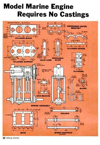
Today after a lot of time with my CAD software I am starting work on a modified steam engine from a Jan. 1953 Popular Science magazine.

You have all probably seen this engine at some time.

A_zps96adf142.jpg
B_zps17bdd3c8.jpg


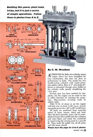
I saw a video of one of these running and it had a very unique sound.

https://www.youtube.com/watch?v=_TwRhMlzf58

I have decided to make a modified version. Mine will have a reverse lever and other modifications, but basically the same overall design.

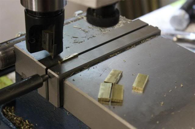
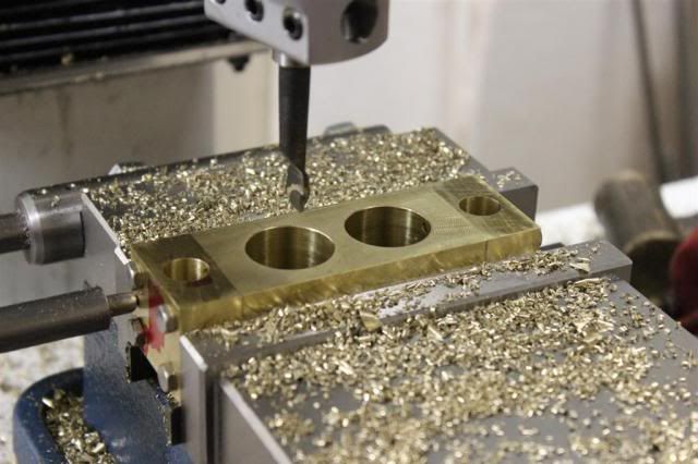
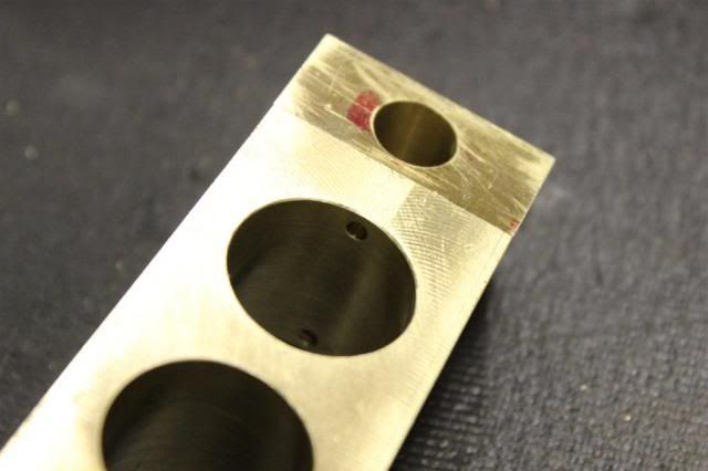
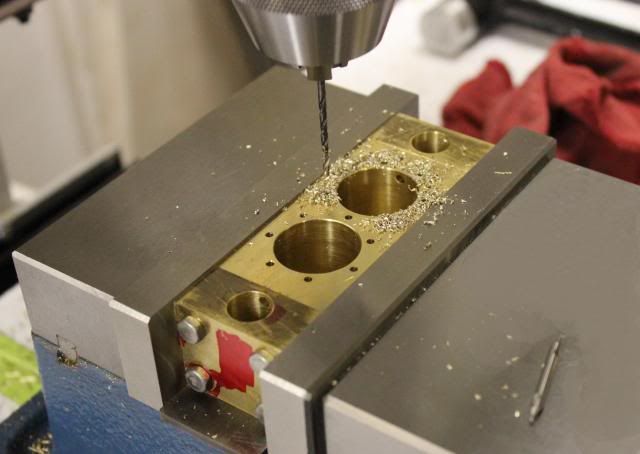
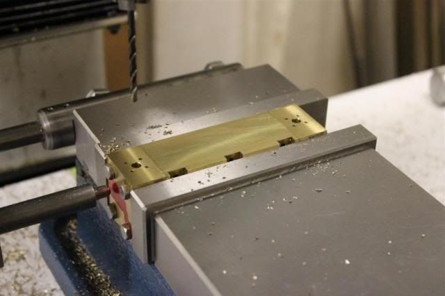
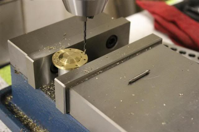
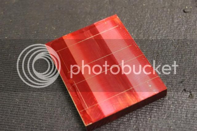
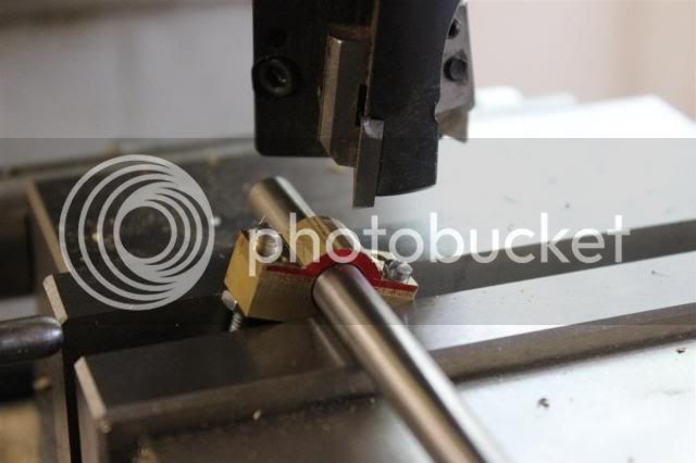
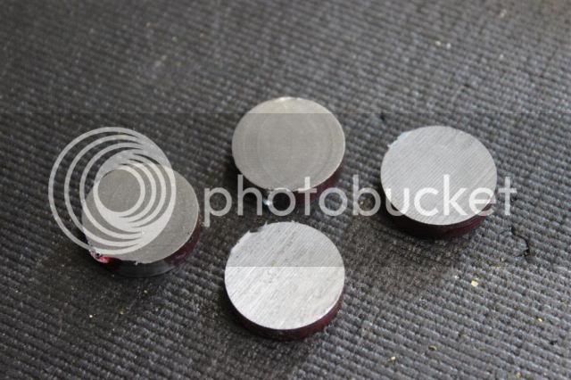
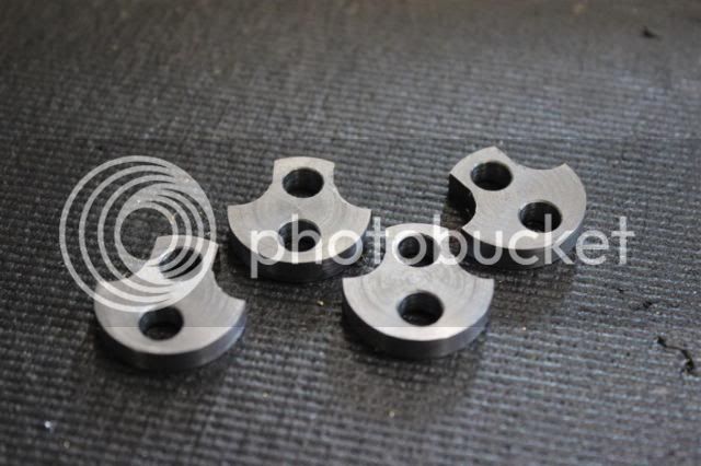
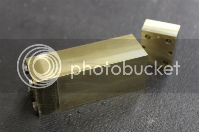
Today I cut my first chips. I am starting with the heart of the engine. The cylinder block. If you have ever looked at the drawings you will see that they call out drilling steam passages from the end into the cylinder. which later get blocked off.

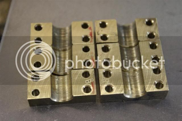
I didn't really like that so I divided the cylinder block into 3 pieces. Cutting off the steam chests from end. This allows me to drill the passages into the facing parts which will later be screwed together concealing them.

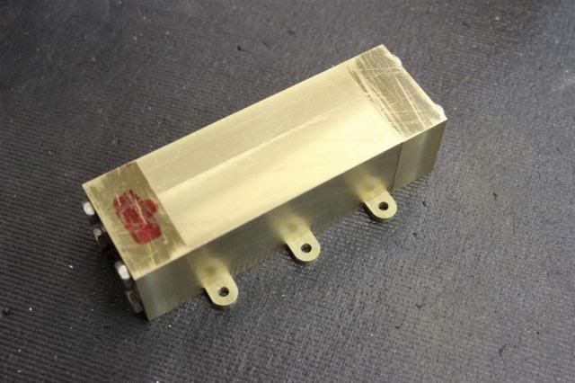
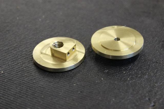
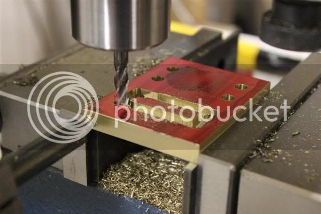
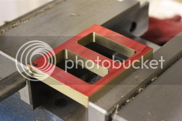
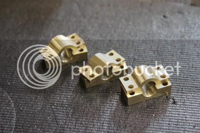
Here you can see the 3 pieces:

002_zpsdcf4043d.jpg


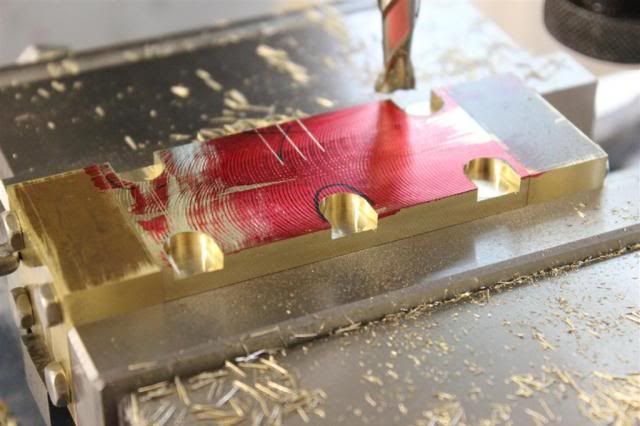
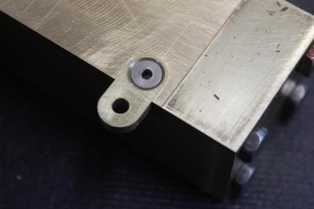
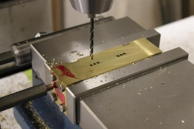
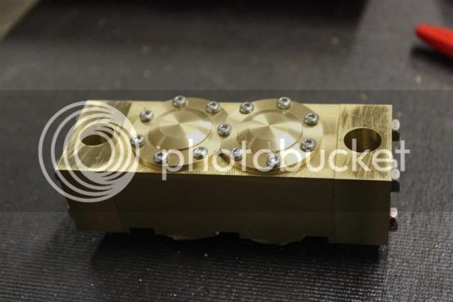
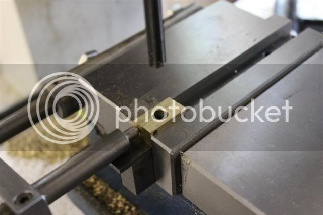
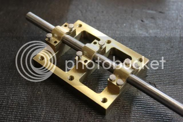
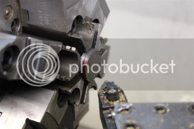
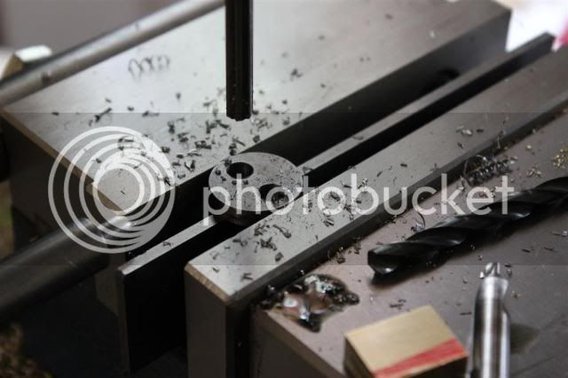
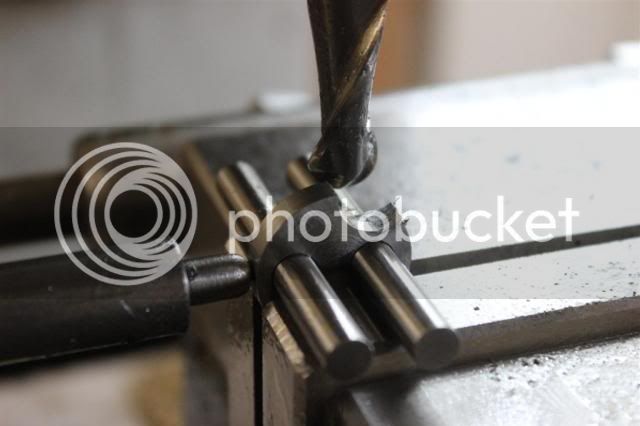
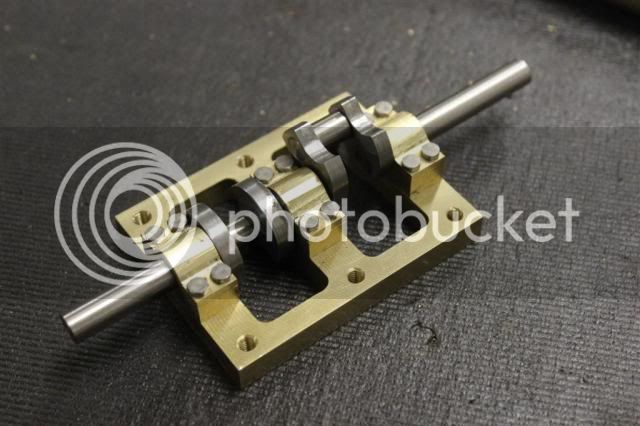
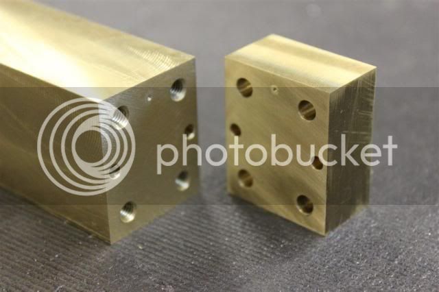
And here the two passages. They lead nowhere right now the will before I am done with this part. You can also see a dimple I added to each surface so that everything always goes back together the same way.

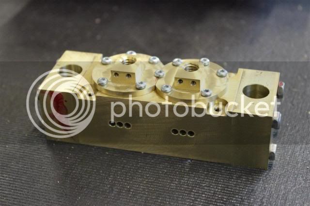
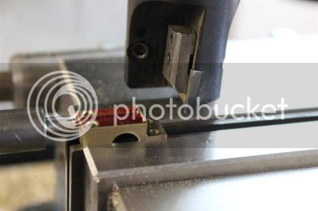
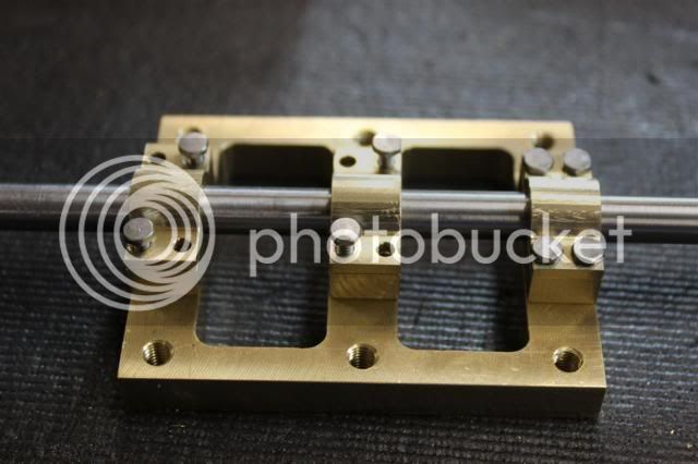
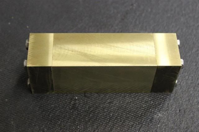
I lapped the surfaces for a perfect fit.

001_zps3a0857a9.jpg


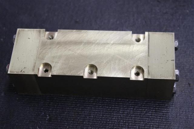
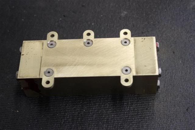
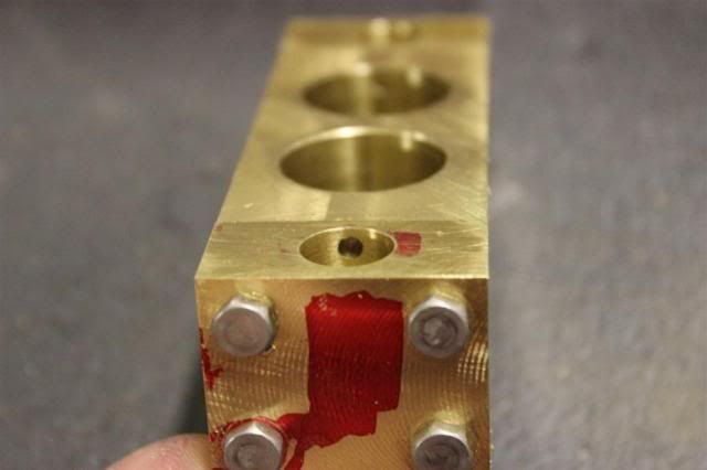
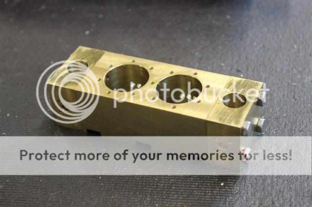
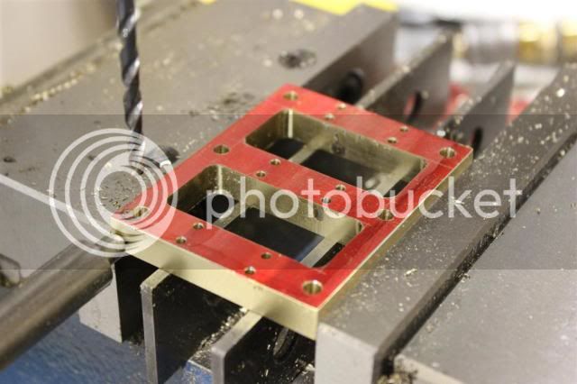
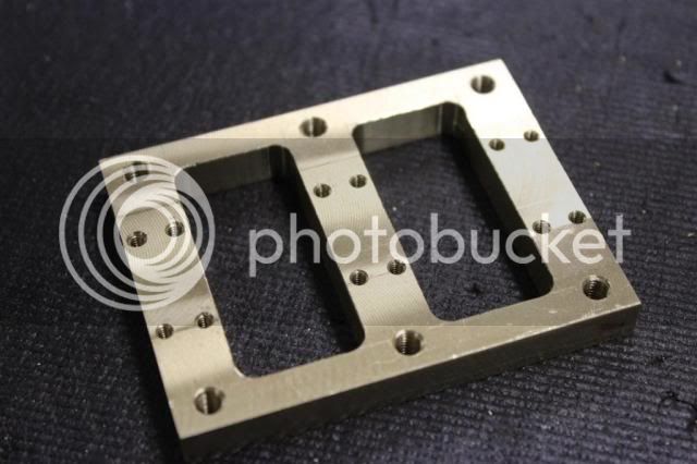
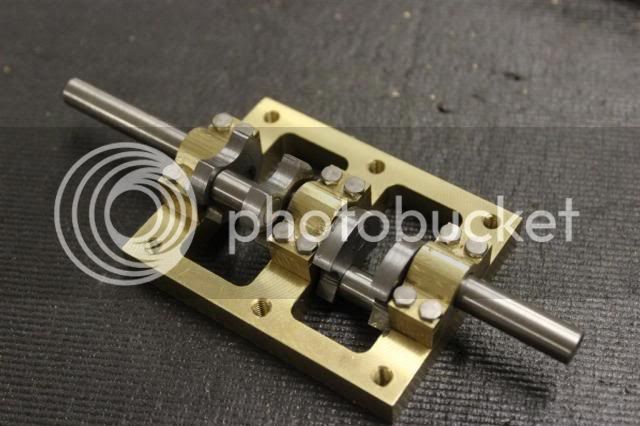
Here you can see the entire cylinder block assembled. I plan on leaving them assembled until everything is completed. Then I will take a very light pass on all the surfaces and polish them. Not sure if I want a matte or shiny finish. But either way it will hide the seems.

003_zpsbe641f78.jpg


Anyway that's my first day and the start of my new project.

Gary
 
Hi Gary,
That should make a very nice little engine when completed.

<<You can also see a dimple I added to each surface so that everything always goes back together the same way.>>

And thank you, ..thank you, ..thank you, ..for concealing the dimple on the mating faces! In my view, there is nothing that spoils a nicely made model engine more than bl***y great centre punch marks on adjacent joining faces!

Keep up the good work.

Cheers, Norman.
 
Anyway you can post the scans in a slightly larger format? would be nice to be able to read the text and sizes.

Looks like a great little engine.

Rob
 
Anyway you can post the scans in a slightly larger format? would be nice to be able to read the text and sizes.

Looks like a great little engine.

Rob

Rob,

Sorry, I posted them just so people would know what I was talking about.

You can see the entire article HERE

Gary
 
Last edited:
Got some more done today.

One of the modifications I am making is to eliminate the plate between the columns and the cylinder block.

What I'm doing is adding tabs directly to the bottom of the cylinder block. I think this looks cleaner.

First I machine some pockets for the tabs.

004_zpsddda9da2.jpg


The drill and tap holes to complete this part.

005_zps7efacef0.jpg


I made the tabs from some 1" wide stock I had.

006_zpsedc54d22.jpg


Drilled the holes and then on to the rotary table to round the ends

007_zpsc8191646.jpg


Then I put it all together.

008_zps8076ef1f.jpg


They really turned out clean. I will take a clean up pass with a fly cutter when I'm done so the joints should disappear.

009_zps92330c49.jpg


And here is everything complete.

010_zpsf2450b07.jpg


I'll remove them and put them back on after machining is done on the cylinder block.

Thanks it for now.

Gary
 
About the best and clearest plans for this engine are available HERE

There are some junk ones out there.

Gary
 
I've always liked this one as well. One question with regards to the cylinder block. If you drilled and plugged as drawn wouldn't those also disappear with final finishing and be less work than cutting, drilling, tapping, lapping and then finishing?
 
I've always liked this one as well. One question with regards to the cylinder block. If you drilled and plugged as drawn wouldn't those also disappear with final finishing and be less work than cutting, drilling, tapping, lapping and then finishing?


I had thought about plugging the holes. Plugging the holes was not in the drawings or the text. It did mention the sleeve for the valve have the holes drilled in one side that then rotated 180° to block them. I mentions holding the sleeve in with a set screw. Now that sleeve as called out has a wall thickness of 1/32" so I don't see how you could use a set screw without deforming the sleeve. I'll show how I plan to deal with that later.

I had another motive for doing it the way I did. I was going to mention it later. I added 1/4" to each of the blocks to increase the total length of the cylinder block from 4" to 4.5". The purpose of this was to create more room for the reversing gear I will be adding.

Gary
 
Completed the cylinder block yesterday.

Here I've just finished boring the cylinder holes. The valve bores have already been done.
011_zps5165b9e2.jpg


You can see the passages from the valve to the cylinder in these next two photos.
013_zpsce7855f2.jpg


012_zps455d9b9c.jpg


The holes for the cylinder covers.

014_zps124eb005.jpg


The exhaust ports

015_zps6622861d.jpg


and the input ports.

016_zpsc67e8daf.jpg


and finally the completed cylinder block!

I'll leave it like this for all the test fitting and getting it running. After all is done I'll strip it all down to finish the surfaces on all the parts.

018_zps3cce1cbc.jpg


Next the upper and lower cylinder covers.

Gary
 
Got the upper and lower cylinder covers done.

Being so thin makes them a little hard to hold. You really have to plan out your operations in advance.

018_zps7e705940.jpg


Then on to the lower cover. The rotary table rounds off the part where the gland nut is installed.

019_zpsc026ddfd.jpg


Shaping is complete, now on to the the mounting holes.

020_zps9a13c247.jpg


The bolt hole feature of my DRO saves a lot of time doing the math!

021_zps673fa47b.jpg


The upper covers complete. Using some temporary screws until the ones I ordered get here.

023_zpsffca8ca1.jpg


And also the bottom.

025_zps8aba4410.jpg


You might notice here another departure from the plans. The plan calls for a bracket to fasten the top of the crosshead guide. To eliminate another part
I incorporated the mounting holes into the bottom cover.

Now that the top end is complete, next I will start work on the bottom.

The base plate is next.

Gary
 
are the lower cylinder covers on backwards? thought the crosshead guide was on the side with 3 supports?

Edit, Nope thats right!
 
are the lower cylinder covers on backwards? thought the crosshead guide was on the side with 3 supports?

Edit, Nope thats right!


No, you are correct! Looks like I will be adding the 6th column after all. I'm glad you caught that now rather than me finding out when I did the final assemble.

That means another tab one the cylinder block after all. Thanks!

Gary
 
Got the base done yesterday.

Here it is all scribed:

PS-027_zps7eb09d86.jpg


Midway through cut. I drilled undersized holes in the corners so the endmill won't get sucked into the corners.

PS-028_zps65afe356.jpg


Half way there.

PS-029_zps6388635e.jpg


Now some holes to finish it up.

PS-030_zpsfec20014.jpg


And finally done. I added the 6th tapped hole in the middle for the extra column I will need.

PS-031_zpse92d7dca.jpg


Crankshaft bearing blocks next.

Gary
 
Now for the bearing blocks. Here I have already squared up, drilled the mounting holes and a rough bearing hole. Just reaming them now.

PS-032_zps373129a8.jpg


And here they are. The bore is rougher than I wanted but they will get lapped anyway. Here you can also see the dimples and put on each set. This is to assure that the pairs stay together and in the correct orientation.

PS-033_zpscdd75334.jpg


Here I'm just roughing the cap to shape.

PS-034_zpsa307eb67.jpg


The only way I figured out to get a nice small radius in the corner is to use my indexable endmill. I just take a pass, move it a little, take another pass and so on.

PS-035_zpsdf8e013f.jpg


Here they are. Just need some smoothing out on the radius.

PS-036_zpsb25d0145.jpg


I couldn't resist a mock up.

PS-037_zps941ee6d2.jpg


PS-038_zpse1662636.jpg


Coming up is the crankshaft.

Gary
 
Now before you say anything I know this is not the correct placement for the counterweights. It's just for looks. I didn't like the rectangular blocks like called out in the print.

That being said here are the blanks I started with.

PS-039_zps738505b4.jpg


I used the lathe to bring them to final thickness.

PS-040_zpsd6c65244.jpg


Then drilled and reamed the holes to .250.

PS-041_zpsfa20d1a2.jpg


Then I used a ball and flat endmill to machine the counterweights.

PS-042_zps56ad2041.jpg


Here then are completed except for cleaning up.

PS-043_zpsad018431.jpg


I didn't want to bore you showing the shafts being made. The .312 SS shafts are just brought to length then the ends turned down to .251 for a press fit into the counterweights.

Here they are all assembled. It took some time on the lathe to get everything straight after the press fits. Then more time for lapping the shafts to the bearings, but everything fits perfectly now.

PS-044_zpse9f6ed2b.jpg


PS-045_zpsbed92bb1.jpg


Next is the connecting rods for the pistons.

Gary
 

Latest posts

Back
Top