Having recently finished my third of elmer's engines I was looking for the next project to tackle. Browsing through my library of "some day" projects I came across Elmer's Turbine/Pump set. While not real interested in the turbine itself, I thought the pump itself would make a good project of its own, giving my other engines something to drive & to show them doing real work.
I thought the pump would also give me the opportunity to practice some techniques not used to date - such as boring a blind hole, and a chance to try out my new rotary table.
In addition, since the design has a low part count, I thought I'd try making two at the same time to see if I was capable of producing two of each part to the same dimensions (within reasonable tolerances") )
)
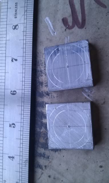
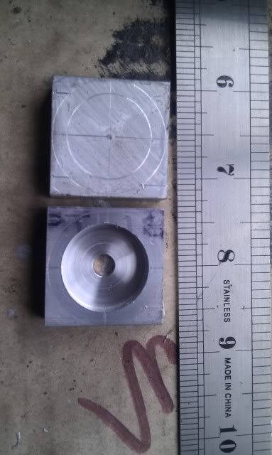
To start I cut two pieces of 6061 aluminium & milled to size (1-1/4 sq) & marked out
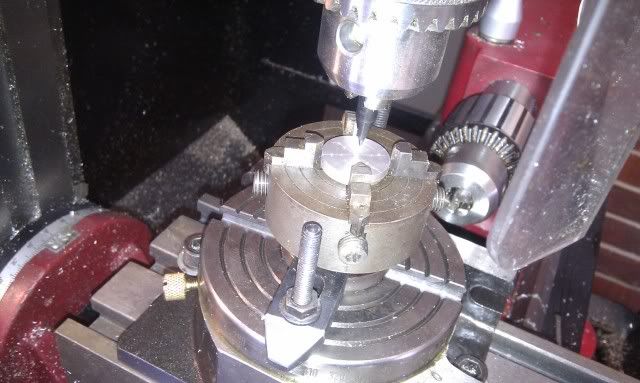
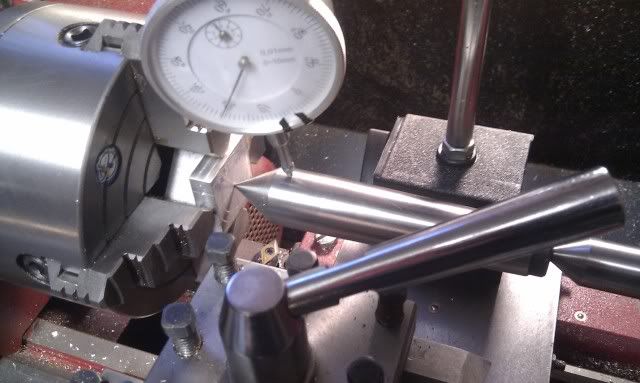
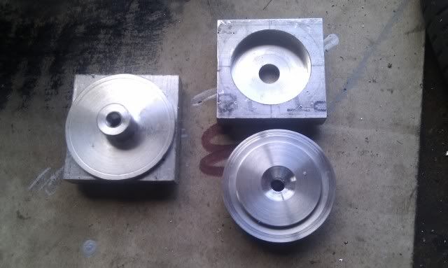
These were then centred in the 4-jaw (eventually), drilled through 1/4" & then bored out.
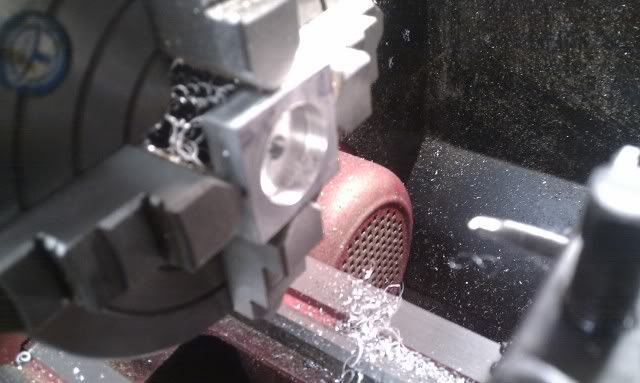
So far so good, both cavities were slightly oversize, but both the same (within .02mm). The first one went well, but the second seemed to chatter a little (even after a rub on the tool with the diamond file) but as its not a piston bore I wasn't too concerned with finish.
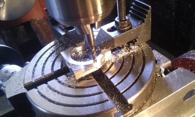
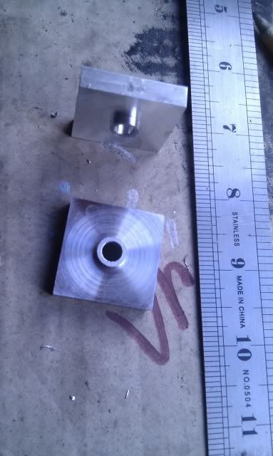
They were then reversed, re-centred and the back turned down to form the bearing spigot
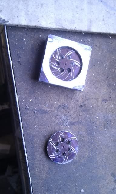
Digging through the scrap box I found some 1-1/2 aluminium bar & turned down the two "heads".
This completes the progress for one weekend, hopefully time will allow further progress new week
Tony.
I thought the pump would also give me the opportunity to practice some techniques not used to date - such as boring a blind hole, and a chance to try out my new rotary table.
In addition, since the design has a low part count, I thought I'd try making two at the same time to see if I was capable of producing two of each part to the same dimensions (within reasonable tolerances
) To start I cut two pieces of 6061 aluminium & milled to size (1-1/4 sq) & marked out
These were then centred in the 4-jaw (eventually), drilled through 1/4" & then bored out.
So far so good, both cavities were slightly oversize, but both the same (within .02mm). The first one went well, but the second seemed to chatter a little (even after a rub on the tool with the diamond file) but as its not a piston bore I wasn't too concerned with finish.
They were then reversed, re-centred and the back turned down to form the bearing spigot
Digging through the scrap box I found some 1-1/2 aluminium bar & turned down the two "heads".
This completes the progress for one weekend, hopefully time will allow further progress new week
Tony.